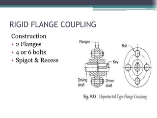
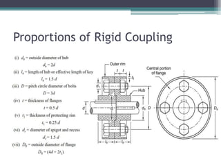
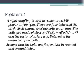
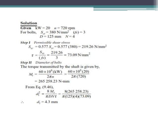
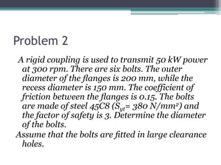
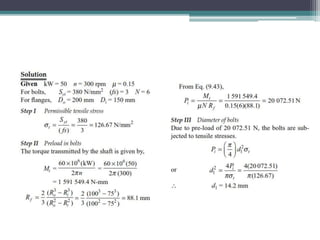
SHAFT COUPLINGS – Rigid Flange
D. Narendra Varma,
Assistant Professor,
Mechanical Engineering Dept.,
Miracle Educational society Group of Institutions.
RIGID FLANGE COUPLING
Construction
• 2 Flanges
• 4 or 6 bolts
• Spigot & Recess
PROTECTIVE TYPE RIGID COUPLING
• Protects operator
against injuries
Advantages
• High torque
transmitting capacity
• Easy to assemble &
dismantle
• Simple in construction
• Easy to design &
manufacture
Disadvantages
• Cannot tolerate misalignment between two
shafts
• Used only where the motion is free from shocks
& vibrations
• Requires more radial space
Proportions of Rigid Coupling
No. of bolts
Analysis of Rigid Coupling
Design Procedure for Rigid Flange Coupling
Problem 1
A rigid coupling is used to transmit 20 kW
power at 720 rpm. There are four bolts and the
pitch circle diameter of the bolts is 125 mm. The
bolts are made of steel 45C8 (Syt = 380 N/mm2)
and the factor of safety is 3. Determine the
diameter of the bolts.
Assume that the bolts are finger tight in reamed
and ground holes.
Problem 2
A rigid coupling is used to transmit 50 kW power
at 300 rpm. There are six bolts. The outer
diameter of the flanges is 200 mm, while the
recess diameter is 150 mm. The coefficient of
friction between the flanges is 0.15. The bolts
are made of steel 45C8 (Syt= 380 N/mm2) and
the factor of safety is 3. Determine the diameter
of the bolts.
Assume that the bolts are fitted in large clearance
holes.
Problem 3
• It is required to design a rigid type of flange
coupling to connect two shafts. The input shaft
transmits 37.5 kW power at 180 rpm to the
output shaft through the coupling. The service
factor for the application is 1.5, i.e., the design
torque is 1.5 times of the rated torque. Select
suitable materials for various parts of the
coupling, design the coupling and specify the
dimensions of its components.
References:
1. Machine Design - V.Bandari .
2. Machine Design – R.S. Khurmi
3. Design Data hand Book - S MD Jalaludin.

Shaft couplings 3 rigid flange coupling

  • 1.
    SHAFT COUPLINGS –Rigid Flange D. Narendra Varma, Assistant Professor, Mechanical Engineering Dept., Miracle Educational society Group of Institutions.
  • 2.
    RIGID FLANGE COUPLING Construction •2 Flanges • 4 or 6 bolts • Spigot & Recess
  • 3.
    PROTECTIVE TYPE RIGIDCOUPLING • Protects operator against injuries Advantages • High torque transmitting capacity • Easy to assemble & dismantle • Simple in construction • Easy to design & manufacture
  • 4.
    Disadvantages • Cannot toleratemisalignment between two shafts • Used only where the motion is free from shocks & vibrations • Requires more radial space
  • 5.
  • 6.
  • 7.
  • 8.
  • 9.
    Design Procedure forRigid Flange Coupling
  • 11.
    Problem 1 A rigidcoupling is used to transmit 20 kW power at 720 rpm. There are four bolts and the pitch circle diameter of the bolts is 125 mm. The bolts are made of steel 45C8 (Syt = 380 N/mm2) and the factor of safety is 3. Determine the diameter of the bolts. Assume that the bolts are finger tight in reamed and ground holes.
  • 13.
    Problem 2 A rigidcoupling is used to transmit 50 kW power at 300 rpm. There are six bolts. The outer diameter of the flanges is 200 mm, while the recess diameter is 150 mm. The coefficient of friction between the flanges is 0.15. The bolts are made of steel 45C8 (Syt= 380 N/mm2) and the factor of safety is 3. Determine the diameter of the bolts. Assume that the bolts are fitted in large clearance holes.
  • 15.
    Problem 3 • Itis required to design a rigid type of flange coupling to connect two shafts. The input shaft transmits 37.5 kW power at 180 rpm to the output shaft through the coupling. The service factor for the application is 1.5, i.e., the design torque is 1.5 times of the rated torque. Select suitable materials for various parts of the coupling, design the coupling and specify the dimensions of its components.
  • 20.
    References: 1. Machine Design- V.Bandari . 2. Machine Design – R.S. Khurmi 3. Design Data hand Book - S MD Jalaludin.