Download as PDF, PPTX

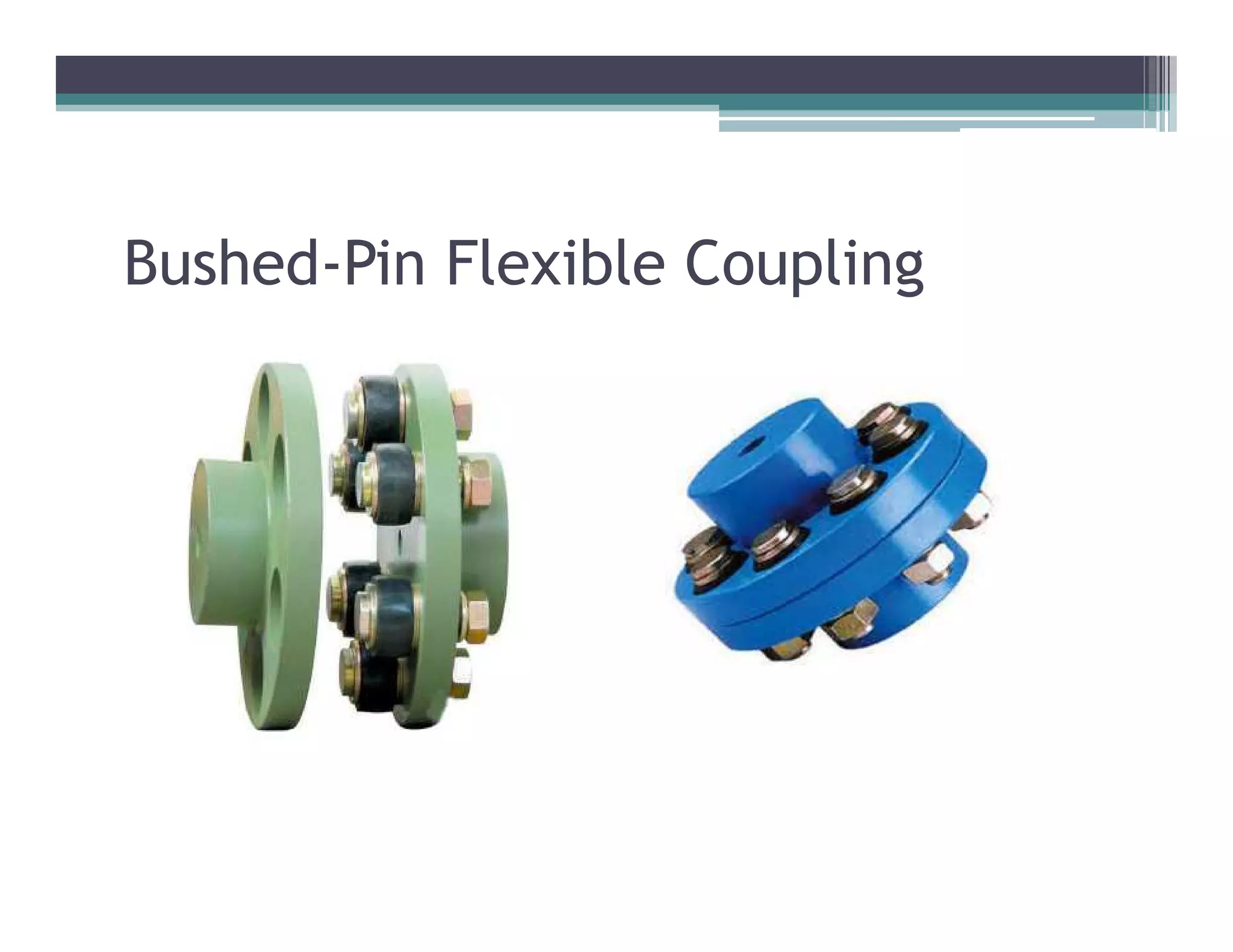


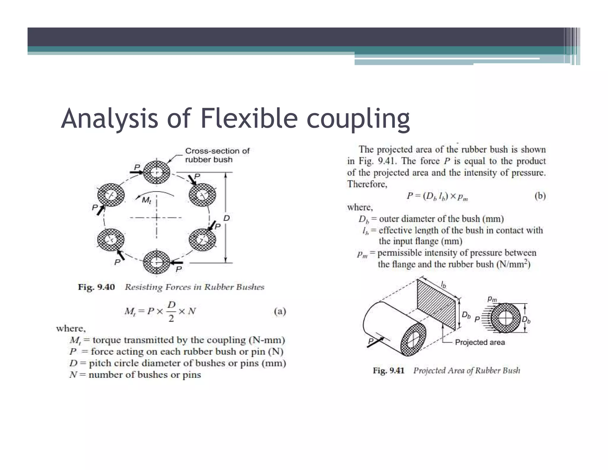
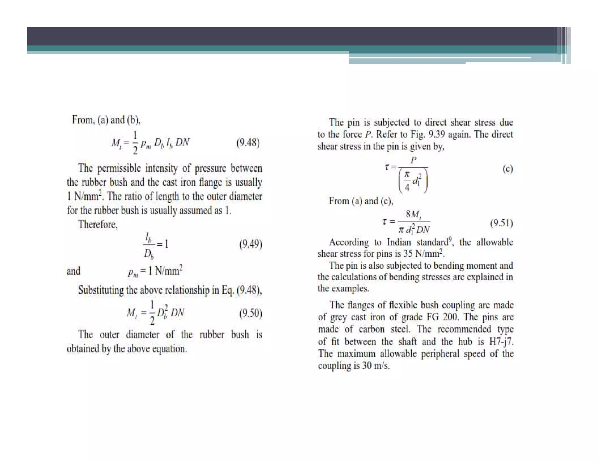


The document discusses bushed pin type shaft couplings, including their classification, advantages, and disadvantages, focusing on their ability to tolerate misalignments and absorb vibrations. It details design considerations and provides problems for calculating pin diameters by shear and bending stresses for flexible couplings used in various applications. Reference materials for further information on machine design are also included.