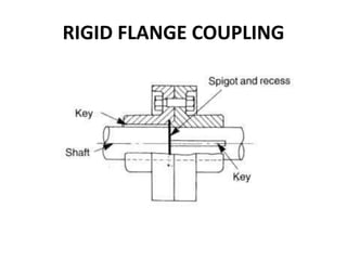
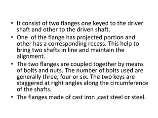
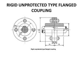
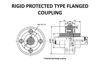
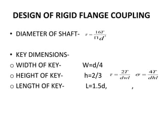
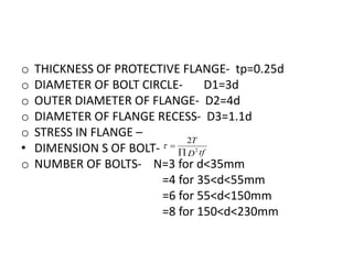
G.H.PATEL COLLEGE OF
ENGINEERING & TECH.
MACHINE DESIGN & INDUSTRIAL
DRAFTING(2141907)
•ENROLLMENT NO:
140110119115=TRASADIYA UTTAM
RIGID FLANGE COUPLING
• It consist of two flanges one keyed to the driver
shaft and other to the driven shaft.
• One of the flange has projected portion and
other has a corresponding recess. This help to
bring two shafts in line and maintain the
alignment.
• The two flanges are coupled together by means
of bolts and nuts. The number of bolts used are
generally three, four or six. The two keys are
staggered at right angles along the circumference
of the shafts.
• The flanges made of cast iron ,cast steel or steel.
The rigid flange coupling are of three types
1) UNPROTECTED TYPE RIGID FLANGE COUPLING
2) PROTECTED TYPE RIGID FLANGE COUPLING
3) MARINE TYPE RIGID FLANGE COUPLING
RIGID UNPROTECTED TYPE FLANGED
COUPLING
RIGID PROTECTED TYPE FLANGED
COUPLING
DESIGN OF RIGID FLANGE COUPLING
• DIAMETER OF SHAFT-
• KEY DIMENSIONS-
o WIDTH OF KEY- W=d/4
o HEIGHT OF KEY- h=2/3
o LENGTH OF KEY- L=1.5d, ,
d
T
3
16


dwl
T2

dhl
T4

• DIMENSIONS OF HUB-
o LENGTH OF HUB=LENGTH OF KEY(l)
o OUTER DIAMETER- D=2d
o STRESS IN HUB-
• DIMENSIONS OF FLANGE-
o THICKNESS OF FLANGE- tf=0.5d
)1(
16
43
KD
T


o THICKNESS OF PROTECTIVE FLANGE- tp=0.25d
o DIAMETER OF BOLT CIRCLE- D1=3d
o OUTER DIAMETER OF FLANGE- D2=4d
o DIAMETER OF FLANGE RECESS- D3=1.1d
o STRESS IN FLANGE –
• DIMENSION S OF BOLT-
o NUMBER OF BOLTS- N=3 for d<35mm
=4 for 35<d<55mm
=6 for 55<d<150mm
=8 for 150<d<230mm
tfD
T
2
2


• DIAMETER OF BOLT- (d)
dDN
T
2
1
8


dtfDN
T
1
2


USES
To provide for misalignment of the shafts or
to introduce mechanical flexibility.
To reduce the transmission of shock loads
from one shaft to another.
To introduce protection against overloads.
To connect driving and the driven par.
To transfer power one end to another
end.(ex: motor transfer power to pump
through coupling.
THANK YOU...

couling and types of coupling

  • 1.
    G.H.PATEL COLLEGE OF ENGINEERING& TECH. MACHINE DESIGN & INDUSTRIAL DRAFTING(2141907) •ENROLLMENT NO: 140110119115=TRASADIYA UTTAM
  • 2.
  • 3.
    • It consistof two flanges one keyed to the driver shaft and other to the driven shaft. • One of the flange has projected portion and other has a corresponding recess. This help to bring two shafts in line and maintain the alignment. • The two flanges are coupled together by means of bolts and nuts. The number of bolts used are generally three, four or six. The two keys are staggered at right angles along the circumference of the shafts. • The flanges made of cast iron ,cast steel or steel.
  • 4.
    The rigid flangecoupling are of three types 1) UNPROTECTED TYPE RIGID FLANGE COUPLING 2) PROTECTED TYPE RIGID FLANGE COUPLING 3) MARINE TYPE RIGID FLANGE COUPLING
  • 5.
    RIGID UNPROTECTED TYPEFLANGED COUPLING
  • 6.
    RIGID PROTECTED TYPEFLANGED COUPLING
  • 7.
    DESIGN OF RIGIDFLANGE COUPLING • DIAMETER OF SHAFT- • KEY DIMENSIONS- o WIDTH OF KEY- W=d/4 o HEIGHT OF KEY- h=2/3 o LENGTH OF KEY- L=1.5d, , d T 3 16   dwl T2  dhl T4 
  • 8.
    • DIMENSIONS OFHUB- o LENGTH OF HUB=LENGTH OF KEY(l) o OUTER DIAMETER- D=2d o STRESS IN HUB- • DIMENSIONS OF FLANGE- o THICKNESS OF FLANGE- tf=0.5d )1( 16 43 KD T  
  • 9.
    o THICKNESS OFPROTECTIVE FLANGE- tp=0.25d o DIAMETER OF BOLT CIRCLE- D1=3d o OUTER DIAMETER OF FLANGE- D2=4d o DIAMETER OF FLANGE RECESS- D3=1.1d o STRESS IN FLANGE – • DIMENSION S OF BOLT- o NUMBER OF BOLTS- N=3 for d<35mm =4 for 35<d<55mm =6 for 55<d<150mm =8 for 150<d<230mm tfD T 2 2  
  • 10.
    • DIAMETER OFBOLT- (d) dDN T 2 1 8   dtfDN T 1 2  
  • 11.
    USES To provide formisalignment of the shafts or to introduce mechanical flexibility. To reduce the transmission of shock loads from one shaft to another. To introduce protection against overloads. To connect driving and the driven par. To transfer power one end to another end.(ex: motor transfer power to pump through coupling.
  • 12.