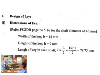
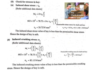
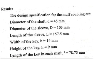
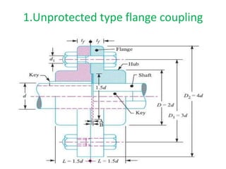
Downloaded 26 times


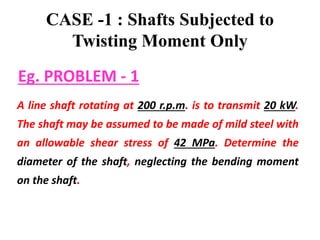


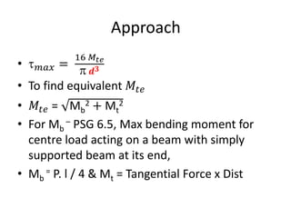


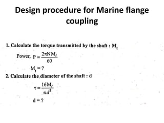
![Approach
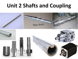
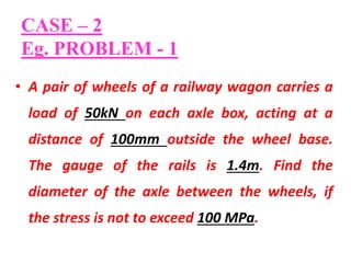
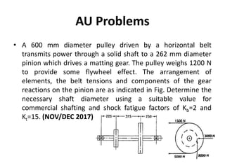
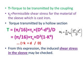
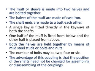
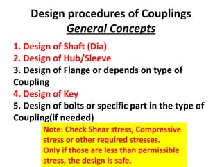
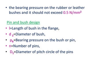
• 𝑚𝑎𝑥 =
16 𝑀𝑡𝑒
𝒅𝟑
• To find equivalent 𝑀𝑡𝑒
• 𝑀𝑡𝑒 = (k.Mb)2 + (k.Mt)2
• 𝑏 =
32 𝑀𝑏
𝒅𝟑
• To find equivalent 𝑀𝑏
• 𝑀𝑡𝑒 =1/2 [𝑀𝑏. 𝑘 + (k.Mb)2 + (k.Mt)2]](https://image.slidesharecdn.com/unit2shaftsandcoupling-221127154819-39a85298/85/Unit-2-Shafts-and-Coupling-pptx-45-320.jpg)


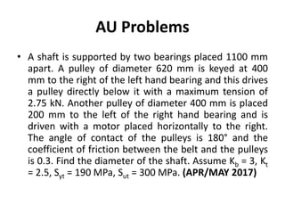


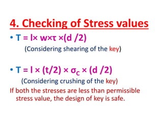


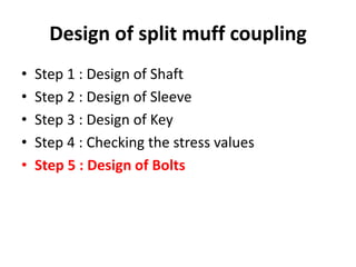


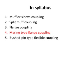


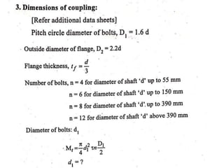


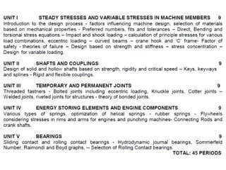
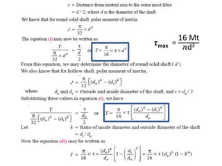
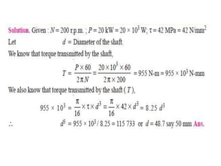
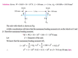
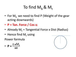
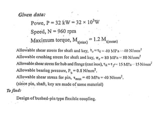
![• Direct shear stress due to pure torsion in the
coupling halve
• τ=W/[ (π/4) (d 1
2 )]
• maximum bending moment on the pin
• M =W (l/2 +5mm)
• bending stress
σ= M / Z
= W (l/2 +5mm)/ (π/32) (d 1
3)](https://image.slidesharecdn.com/unit2shaftsandcoupling-221127154819-39a85298/85/Unit-2-Shafts-and-Coupling-pptx-218-320.jpg)
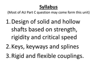
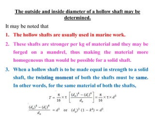
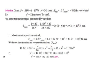
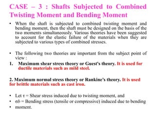
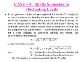
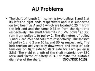
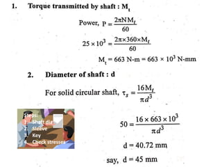
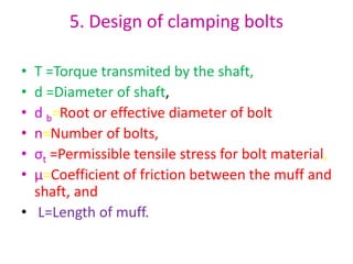
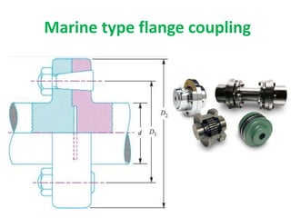
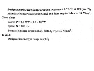
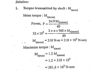
![• Maximum principal stress
= 1/2[σ +(σ+4τ2 ) 1/2]
• maximum shear stress on the pin
= 1/2(σ+4τ2 ) 1/2
• The value of maximum principal stress varies
from 28 to 42 MPa](https://image.slidesharecdn.com/unit2shaftsandcoupling-221127154819-39a85298/85/Unit-2-Shafts-and-Coupling-pptx-219-320.jpg)


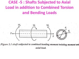
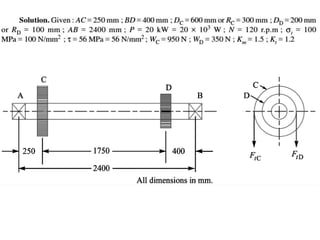
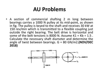
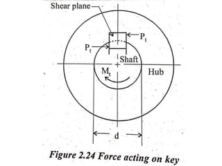
1. The document describes a horizontal shaft supported by bearings at each end that carries two gears. 2. Gears C and D are located 250mm and 400mm from their respective bearings and have pitch diameters of 600mm and 200mm. 3. The shaft transmits 20kW of power at 120rpm, delivered at gear C and taken out at gear D, with vertical tooth pressures on each gear. 4. The question asks to determine the shaft diameter if the working stresses are 100MPa in tension and 56MPa in shear.