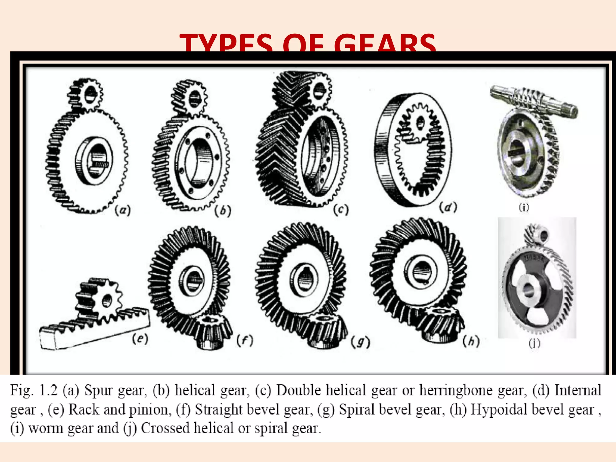
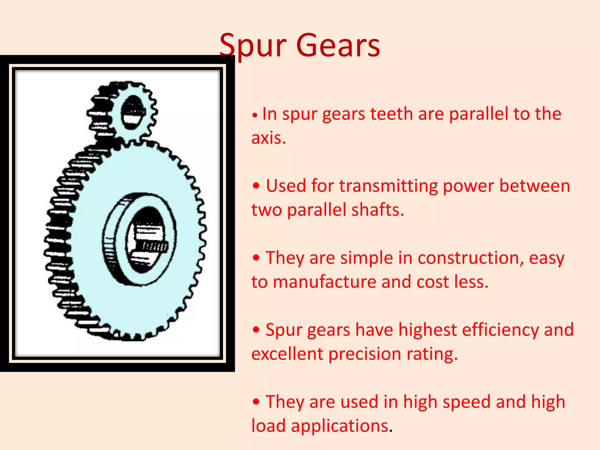
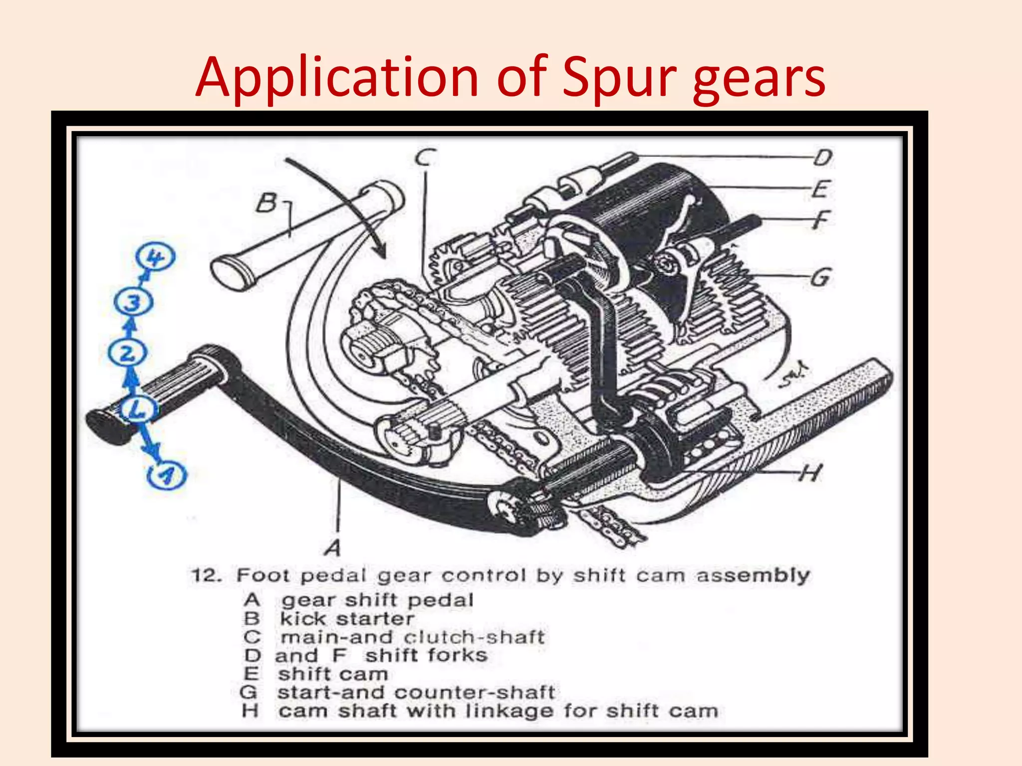
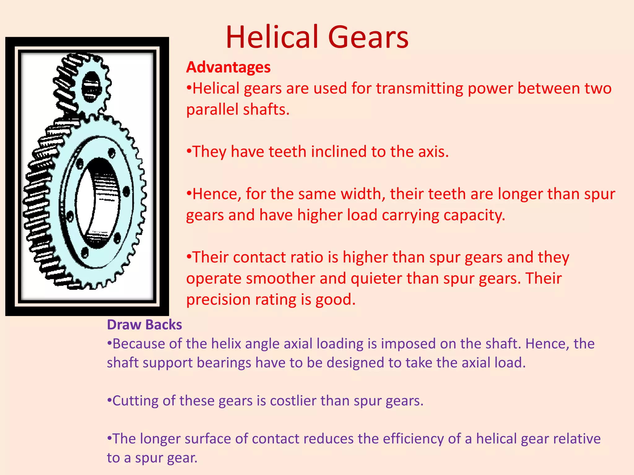
Gear Manufacturing
•Gear Introduction
•Types of gears and their applications
•Gear Manufacturing classification
•Gear forming
•Gear generation
Gear Introduction
• Gears are toothed members which transmit
power or motion between two shafts, by
meshing without any slip.
• Hence, gear drives are also called positive
drives.
• In any pair of gears, the smaller one is called
pinion and the larger one is called gear
immaterial of which is driving the other
TYPES OF GEARS
Spur Gears
• In spur gears teeth are parallel to the
axis.
• Used for transmitting power between
two parallel shafts.
• They are simple in construction, easy
to manufacture and cost less.
• Spur gears have highest efficiency and
excellent precision rating.
• They are used in high speed and high
load applications.
Application of Spur gears
Helical Gears
Advantages
•Helical gears are used for transmitting power between two
parallel shafts.
•They have teeth inclined to the axis.
•Hence, for the same width, their teeth are longer than spur
gears and have higher load carrying capacity.
•Their contact ratio is higher than spur gears and they
operate smoother and quieter than spur gears. Their
precision rating is good.
Draw Backs
•Because of the helix angle axial loading is imposed on the shaft. Hence, the
shaft support bearings have to be designed to take the axial load.
•Cutting of these gears is costlier than spur gears.
•The longer surface of contact reduces the efficiency of a helical gear relative
to a spur gear.
DOUBLE HELICAL OR HERRINGBONE GEARS
Double helical or Herring-bone gears used for
transmitting power between two parallel shafts.
They have opposing helical teeth which nullify two
axial thrusts.
Though their load capacity is very high, manufacturing
difficulty makes them costlier than single helical gear.
These gears find wide applications in
cement mills and crushers.
INTERNAL GEARS
• Internal gears are used for transmitting power
between two parallel shafts.
• In these gears, annular wheels are having teeth on the
inner periphery.
Applications of internal gears can be seen in planetary gear drives
of automatic transmissions of automobiles, reduction gearboxes of
cement mills, step-up drives of wind mills.
RACK AND PINION
• Rack is a segment of a gear of infinite diameter.
• The tooth can be spur or helical.
STRAIGHT BEVEL GEARS
• Straight bevel gears are used for transmitting power
between intersecting shafts
• They are suitable for 1:1 and higher velocity ratios.
• They can be used for right-angle or any angular drive.
Automobile differential drive
SPIRAL BEVEL GEARS
• Spiral bevel gears are also used for transmitting
power between intersecting shafts.
• They operate smoother than straight bevel gears
and have higher load capacity.
HYPOIDAL BEVEL GEARS
• These gears are also used for right angle drive in
which the axes do not intersect.
This permits lowering of the pinion axis and avoiding
hump inside the automobile
otherwise needed for the drive line power
transmission.
WORM GEARS
• They are used in right-angle or skew shaft drives.
• The presence of sliding action in the system even though results in
quieter operation, it gives rise to considerable frictional heat.
• Hence, they need good lubrication for heat dissipation and for
improving the efficiency.
• High reductions are possible which results in compact drive.
CROSSED HELICAL GEAR OR SPIRAL GEARS
• They have high helix angle and transmit power
between two non-intersecting non-parallel shafts.
• They have point contact which reduces their load
carrying capacity.
• Hence, they are used for light load applications
only.
Gear Terminology
Gear Manufacturing methods
GEAR CUTTING BY FORMING
• The tooth profile is obtained by using a form
cutting tool. This may be a multiple-toothed
cutter used in milling, broaching machines, and
shaping cutter head, or a single-point tool form
for use in a shaper and a bevel gear planer.
Gear Milling
• The usual practice in gear milling is to mill one tooth
space at a time, after which the blank is indexed to
the next cutting position.
• Figure A shows teeth in a spur gear cut by
peripheral (horizontal) milling with a disk cutter.
• Similarly, end milling can also be used for cutting
teeth in spur or helical gears and is often used for
cutting coarse-pitch teeth in herringbone gears
• In practice, gear milling is usually confined to
– One-of-a-kind replacement gears
– Small-lot production
– Roughing and finishing of coarse-pitch gears
– Finish milling of gears with special tooth forms
Gear Milling
Broaching
• Both external and internal gear teeth, spur or
helical, can be broached, but conventional
broaching is usually confined to cutting teeth in
internal gears.
• Figure shows progressive broach steps in cutting
an internal spur gear. The form of the space
between broached gear teeth corresponds to the
form of the broach teeth.
• The cutting action of any single broach tooth is
similar to that of a single form tool. Each cross
section of the broach has as many teeth as there
are tooth spaces on the gear. The diameter of
each section increases progressively to the major
diameter that completes the tooth form on the
workpiece.
• Broaching is fast, and accurate, but the cost of
tooling is high. Therefore, broaching of gear
Shear cutting
• Shear cutting is a high-production method
for producing teeth in external spur gears.
• The process is not applicable to helical
gears.
• In shear cutting, as in broaching, all tooth
spaces are cut simultaneously and
progressively (Fig. 14).
• Cutting speeds in shear cutting are similar
to those for broaching the same work
metal.
• Machines are available for cutting gears
up to 508 mm (20 in.) in diameter, with
face width up to 152 mm (6 in.).
Shear speed process-contd
• The shear cutting head is mounted in a fixed position,
and the gear blanks are pushed through the head.
• Cutting tools are fed radially into the head, a
predetermined amount for each stroke, until the
required depth of tooth space is reached.
• In shear cutting, some space is required for over-travel,
although most workpieces with integral shoulders or
flanges (such as cluster gears) do have enough clearance
between sections to allow shear cutting to be used.
• Therefore, this process is best suited to large production
runs.
Helical Gear Milling
GEAR CUTTING BY GENERATION
• This technique is based on the fact that two involute gears of
the same module and pitch mesh together—the WP blank and
the cutter.
• So this method makes it possible to use one cutting gear for
machining gears of the same module with a varying number of
teeth.
• Gear generation methods are characterized by their higher
accuracy and machining productivity than gear forming.
• They comprise
– hobbing and gear or rack shaping for the manufacture of spur and
helical gears, worm and worm wheels, and
– bevel gear generation.
Gear Hobbing
• Hobbing is a practical method for cutting teeth in spur gears,
helical gears, worms, worm gears, and many special forms.
• Conventional hobbing machines are not applicable to cutting
bevel and internal gears.
• Tooling costs for hobbing are lower than those for broaching or
shear cutting.
• Therefore, hobbing is used in low-quantity production or even
for a few pieces.
• On the other hand, hobbing is a fast and accurate method
(compared to milling, for example) and is therefore suitable for
medium and high production quantities.
Gear Hobbing
• Hobbing is a generating process in which
both the cutting tool and the workpiece
revolve in a constant relation as the hob
is being fed across the face width of the
gear blank.
• The hob is a fluted worm with form-
relieved teeth that cut into the gear
blank in succession, each in a slightly
different position.
• Instead of being formed in one profile
cut, as in milling, the gear teeth are
generated progressively by a series of
cuts
Gear tooth is generated
progressively by hob
teeth.
Generating action
In gear
generation, the
generating
action and the
forming of the
involute profile
is achieved by
the successive
tangential cuts
taken by the
tooth one after
the other on
the gear blank
Difference between gear forming and gear
generation
Gear forming Gear generation
Form tool of exact shape is used The tangential cutting edge
finishes the profile
Cutting is done using
conventional machine and
methods
Cutting is done on special
machine which have a generating
motion by simulation of gear pair
Intermittent indexing is used Continuous indexing is used
Only one gear with specified
number of teeth can be cut with
a given cutter
The gears can be cut irrespective
of the number of teeth
Low productivity High productivity
Can be used for smaller modules Can be used for larger modules
Hob Cutter
Gear Hobbing
Various products that can be manufactured
by gear hob
Gear Hobbing Machine
Setup for gear hobbing machine
Change gears in Gear Hobbing
• Cutting speed change gears
• Feed change gears
• Index change gears
• Differential change gears
Procedure for cutting the spur gear in hobbing
machine
1. Select the hobbing cutter as per the module, pressure angle and
the profile required
2. Mount the cutter on the arbour and tilt the swivel head to the
lead angle of the hobbing cutter
3. Mount the gear blanks, on the rigid and precision mandrel and
set the tail stock support.
4. Set the speed change gears depending upon the cutting velocity
required, set the index change gears depending upon the
number of tooth required, set the feed change gears depending
upon the material being cut. (Note – No need for setting the
differential change gears for spur gear cutting)
5. Set the required depth of cut.
6. Start the machine and the coolant.
7. Use automatic machining cycle if available.
8. Measure the base tangent length when finished
Cutting action for different types of gearing: (a) spur gear,
(b) helical gear
Hobbing of Helical Gears
• To cut helical gears, the hob is set up so that the thread of the hob
facing the gear blank is directed at the helix angle of the teeth.
• This is done by setting the hob at an angle γ = βg ± αh, where βg is
the helix angle of the helical gear being cut and αh is the helix
angle of the hob.
• If the hand of helical gear and that of the hob are different, the
positive sign is considered; if the hand is the same, the negative
sign should be used.
• Also, the hob attains a continuous feed motion along the axis of
the gear blank .
• In cutting helical gears, an incremental motion is imparted to the
blank, with an angular velocity that would provide one full
additional revolution of the blank during vertical feed of the hob
through a distance equal to the lead of the helical teeth on the
gear.
Rule for tilting the hob cutter for cutting helical
gears
RH HOB LH HOB
RH Gear γ = βg - αh γ = βg + αh
LH Gear γ = βg + αh γ = βg - αh
Generating Worm gears in a hobbing machine
Advantages and Drawbacks of gear
hobbing
• Advantages
– It is a quicker and continuous process, hence high rate of
production is easily obtained
– Almost all types of gear profiles can be generated like
worm, spur, helical, sprockets, cams also.
– Accurate profile is generated
– Multiple gear blanks can be mounted on same arbor and
hobbed simultaneously.
– It is very simple and economical process as compared to
other generating processes
• Draw backs
– Not suitable for generating internal gears
– Not suitable for gears having collars
Gear shaper
• Gear shaping is an important gear cutting
method where small, medium and large size
gears are cut.
• A reciprocating cutting tool is used to generate
the gear tooth one after the other.
• It is a generating process and the machine
kinematic motion is designed in such a way that
the involute profiles are generated.
• Generally adopted for spur, helical and double
helical gears. Internal gears are also cut by this
method.
• The process is mostly adopted for steel gears.
Gear shaper
• The process can be classified
– Gear shaping with disc cutters (Fellows Process)
• Used for cutting spur, helical and internal gear of 15 to
300 mm
– Gear shaping by rack type cutters (Maag process)
• Used for spur, helical and double helical gears of 150 to
1500 mm
– Gear planing by rack type cutters (Sunderland
process)
• Used for spur, helical and double helical gears upto 5000
mm
Gear Shaper - Construction
Procedure for cutting a spur gear
• Select the cutter of required module and pressure
angle. Fit the cutter on the spindle mounting over a
shank.
• Fit the work piece on a short, rigid, precision mandrel
• Set the number of strokes, stroke length and zone of
cutting
• Set the index change gears for the required number of
teeth. Set the feed change gears for the required
circumferential feed rate.
• Set the feed cam depending upon the number of cuts
and set the ratios.
• Set the head nearer to the work for the required depth
and start the machine and coolant.
Procedure for cutting Helical gear in gear shaper
• Helical gear cutting on disc type cutter shaping
machine needs special helical gear shaper cutter
and a helical guide.
• This is not universal and for each angle and hand
of helix they vary. Hence for single piece or small
lot of production, this is not adopted.
– Select the helical gear shaping cutter of required
module and pressure angle. The helix angle of the
cutter should be same but opposite hand of helix
should be used.
– Fit the helical guide on the top of the spindle as per
the required lead of the gear to the cut.
Advantages and drawbacks of gear shaping
• Advantages
– It is faster process, hence suitable for medium and large size
batch production
– Mostly all types of gears like spur gears, rack and pinions,
double helical gears, internal gears, sprockets can be
produced
– Accurate tooth profile is generated
– There is no need to change cutter for cutting the teeth of
different spur gears, if modules are same.
• Drawbacks
– Worm and worm gears cannot be produced
– For helical gears, special helical guide is required.
– Cutting takes place only during cutting stroke. Thus a time
spent in return stroke goes as waste.
– Only one gear can be cut at a time

Gear Manufacturing.ppt

  • 1.
    Gear Manufacturing •Gear Introduction •Typesof gears and their applications •Gear Manufacturing classification •Gear forming •Gear generation
  • 2.
    Gear Introduction • Gearsare toothed members which transmit power or motion between two shafts, by meshing without any slip. • Hence, gear drives are also called positive drives. • In any pair of gears, the smaller one is called pinion and the larger one is called gear immaterial of which is driving the other
  • 3.
  • 4.
    Spur Gears • Inspur gears teeth are parallel to the axis. • Used for transmitting power between two parallel shafts. • They are simple in construction, easy to manufacture and cost less. • Spur gears have highest efficiency and excellent precision rating. • They are used in high speed and high load applications.
  • 5.
  • 6.
    Helical Gears Advantages •Helical gearsare used for transmitting power between two parallel shafts. •They have teeth inclined to the axis. •Hence, for the same width, their teeth are longer than spur gears and have higher load carrying capacity. •Their contact ratio is higher than spur gears and they operate smoother and quieter than spur gears. Their precision rating is good. Draw Backs •Because of the helix angle axial loading is imposed on the shaft. Hence, the shaft support bearings have to be designed to take the axial load. •Cutting of these gears is costlier than spur gears. •The longer surface of contact reduces the efficiency of a helical gear relative to a spur gear.
  • 7.
    DOUBLE HELICAL ORHERRINGBONE GEARS Double helical or Herring-bone gears used for transmitting power between two parallel shafts. They have opposing helical teeth which nullify two axial thrusts. Though their load capacity is very high, manufacturing difficulty makes them costlier than single helical gear. These gears find wide applications in cement mills and crushers.
  • 8.
    INTERNAL GEARS • Internalgears are used for transmitting power between two parallel shafts. • In these gears, annular wheels are having teeth on the inner periphery. Applications of internal gears can be seen in planetary gear drives of automatic transmissions of automobiles, reduction gearboxes of cement mills, step-up drives of wind mills.
  • 9.
    RACK AND PINION •Rack is a segment of a gear of infinite diameter. • The tooth can be spur or helical.
  • 10.
    STRAIGHT BEVEL GEARS •Straight bevel gears are used for transmitting power between intersecting shafts • They are suitable for 1:1 and higher velocity ratios. • They can be used for right-angle or any angular drive. Automobile differential drive
  • 11.
    SPIRAL BEVEL GEARS •Spiral bevel gears are also used for transmitting power between intersecting shafts. • They operate smoother than straight bevel gears and have higher load capacity.
  • 12.
    HYPOIDAL BEVEL GEARS •These gears are also used for right angle drive in which the axes do not intersect. This permits lowering of the pinion axis and avoiding hump inside the automobile otherwise needed for the drive line power transmission. WORM GEARS • They are used in right-angle or skew shaft drives. • The presence of sliding action in the system even though results in quieter operation, it gives rise to considerable frictional heat. • Hence, they need good lubrication for heat dissipation and for improving the efficiency. • High reductions are possible which results in compact drive.
  • 13.
    CROSSED HELICAL GEAROR SPIRAL GEARS • They have high helix angle and transmit power between two non-intersecting non-parallel shafts. • They have point contact which reduces their load carrying capacity. • Hence, they are used for light load applications only.
  • 14.
  • 15.
  • 16.
    GEAR CUTTING BYFORMING • The tooth profile is obtained by using a form cutting tool. This may be a multiple-toothed cutter used in milling, broaching machines, and shaping cutter head, or a single-point tool form for use in a shaper and a bevel gear planer.
  • 17.
    Gear Milling • Theusual practice in gear milling is to mill one tooth space at a time, after which the blank is indexed to the next cutting position. • Figure A shows teeth in a spur gear cut by peripheral (horizontal) milling with a disk cutter. • Similarly, end milling can also be used for cutting teeth in spur or helical gears and is often used for cutting coarse-pitch teeth in herringbone gears • In practice, gear milling is usually confined to – One-of-a-kind replacement gears – Small-lot production – Roughing and finishing of coarse-pitch gears – Finish milling of gears with special tooth forms
  • 18.
  • 19.
    Broaching • Both externaland internal gear teeth, spur or helical, can be broached, but conventional broaching is usually confined to cutting teeth in internal gears. • Figure shows progressive broach steps in cutting an internal spur gear. The form of the space between broached gear teeth corresponds to the form of the broach teeth. • The cutting action of any single broach tooth is similar to that of a single form tool. Each cross section of the broach has as many teeth as there are tooth spaces on the gear. The diameter of each section increases progressively to the major diameter that completes the tooth form on the workpiece. • Broaching is fast, and accurate, but the cost of tooling is high. Therefore, broaching of gear
  • 20.
    Shear cutting • Shearcutting is a high-production method for producing teeth in external spur gears. • The process is not applicable to helical gears. • In shear cutting, as in broaching, all tooth spaces are cut simultaneously and progressively (Fig. 14). • Cutting speeds in shear cutting are similar to those for broaching the same work metal. • Machines are available for cutting gears up to 508 mm (20 in.) in diameter, with face width up to 152 mm (6 in.).
  • 21.
    Shear speed process-contd •The shear cutting head is mounted in a fixed position, and the gear blanks are pushed through the head. • Cutting tools are fed radially into the head, a predetermined amount for each stroke, until the required depth of tooth space is reached. • In shear cutting, some space is required for over-travel, although most workpieces with integral shoulders or flanges (such as cluster gears) do have enough clearance between sections to allow shear cutting to be used. • Therefore, this process is best suited to large production runs.
  • 22.
  • 23.
    GEAR CUTTING BYGENERATION • This technique is based on the fact that two involute gears of the same module and pitch mesh together—the WP blank and the cutter. • So this method makes it possible to use one cutting gear for machining gears of the same module with a varying number of teeth. • Gear generation methods are characterized by their higher accuracy and machining productivity than gear forming. • They comprise – hobbing and gear or rack shaping for the manufacture of spur and helical gears, worm and worm wheels, and – bevel gear generation.
  • 24.
    Gear Hobbing • Hobbingis a practical method for cutting teeth in spur gears, helical gears, worms, worm gears, and many special forms. • Conventional hobbing machines are not applicable to cutting bevel and internal gears. • Tooling costs for hobbing are lower than those for broaching or shear cutting. • Therefore, hobbing is used in low-quantity production or even for a few pieces. • On the other hand, hobbing is a fast and accurate method (compared to milling, for example) and is therefore suitable for medium and high production quantities.
  • 25.
    Gear Hobbing • Hobbingis a generating process in which both the cutting tool and the workpiece revolve in a constant relation as the hob is being fed across the face width of the gear blank. • The hob is a fluted worm with form- relieved teeth that cut into the gear blank in succession, each in a slightly different position. • Instead of being formed in one profile cut, as in milling, the gear teeth are generated progressively by a series of cuts Gear tooth is generated progressively by hob teeth.
  • 26.
    Generating action In gear generation,the generating action and the forming of the involute profile is achieved by the successive tangential cuts taken by the tooth one after the other on the gear blank
  • 27.
    Difference between gearforming and gear generation Gear forming Gear generation Form tool of exact shape is used The tangential cutting edge finishes the profile Cutting is done using conventional machine and methods Cutting is done on special machine which have a generating motion by simulation of gear pair Intermittent indexing is used Continuous indexing is used Only one gear with specified number of teeth can be cut with a given cutter The gears can be cut irrespective of the number of teeth Low productivity High productivity Can be used for smaller modules Can be used for larger modules
  • 28.
  • 29.
    Gear Hobbing Various productsthat can be manufactured by gear hob
  • 30.
  • 32.
    Setup for gearhobbing machine
  • 33.
    Change gears inGear Hobbing • Cutting speed change gears • Feed change gears • Index change gears • Differential change gears
  • 34.
    Procedure for cuttingthe spur gear in hobbing machine 1. Select the hobbing cutter as per the module, pressure angle and the profile required 2. Mount the cutter on the arbour and tilt the swivel head to the lead angle of the hobbing cutter 3. Mount the gear blanks, on the rigid and precision mandrel and set the tail stock support. 4. Set the speed change gears depending upon the cutting velocity required, set the index change gears depending upon the number of tooth required, set the feed change gears depending upon the material being cut. (Note – No need for setting the differential change gears for spur gear cutting) 5. Set the required depth of cut. 6. Start the machine and the coolant. 7. Use automatic machining cycle if available. 8. Measure the base tangent length when finished
  • 35.
    Cutting action fordifferent types of gearing: (a) spur gear, (b) helical gear
  • 36.
    Hobbing of HelicalGears • To cut helical gears, the hob is set up so that the thread of the hob facing the gear blank is directed at the helix angle of the teeth. • This is done by setting the hob at an angle γ = βg ± αh, where βg is the helix angle of the helical gear being cut and αh is the helix angle of the hob. • If the hand of helical gear and that of the hob are different, the positive sign is considered; if the hand is the same, the negative sign should be used. • Also, the hob attains a continuous feed motion along the axis of the gear blank . • In cutting helical gears, an incremental motion is imparted to the blank, with an angular velocity that would provide one full additional revolution of the blank during vertical feed of the hob through a distance equal to the lead of the helical teeth on the gear.
  • 38.
    Rule for tiltingthe hob cutter for cutting helical gears RH HOB LH HOB RH Gear γ = βg - αh γ = βg + αh LH Gear γ = βg + αh γ = βg - αh
  • 39.
    Generating Worm gearsin a hobbing machine
  • 40.
    Advantages and Drawbacksof gear hobbing • Advantages – It is a quicker and continuous process, hence high rate of production is easily obtained – Almost all types of gear profiles can be generated like worm, spur, helical, sprockets, cams also. – Accurate profile is generated – Multiple gear blanks can be mounted on same arbor and hobbed simultaneously. – It is very simple and economical process as compared to other generating processes • Draw backs – Not suitable for generating internal gears – Not suitable for gears having collars
  • 41.
    Gear shaper • Gearshaping is an important gear cutting method where small, medium and large size gears are cut. • A reciprocating cutting tool is used to generate the gear tooth one after the other. • It is a generating process and the machine kinematic motion is designed in such a way that the involute profiles are generated. • Generally adopted for spur, helical and double helical gears. Internal gears are also cut by this method. • The process is mostly adopted for steel gears.
  • 42.
    Gear shaper • Theprocess can be classified – Gear shaping with disc cutters (Fellows Process) • Used for cutting spur, helical and internal gear of 15 to 300 mm – Gear shaping by rack type cutters (Maag process) • Used for spur, helical and double helical gears of 150 to 1500 mm – Gear planing by rack type cutters (Sunderland process) • Used for spur, helical and double helical gears upto 5000 mm
  • 43.
    Gear Shaper -Construction
  • 44.
    Procedure for cuttinga spur gear • Select the cutter of required module and pressure angle. Fit the cutter on the spindle mounting over a shank. • Fit the work piece on a short, rigid, precision mandrel • Set the number of strokes, stroke length and zone of cutting • Set the index change gears for the required number of teeth. Set the feed change gears for the required circumferential feed rate. • Set the feed cam depending upon the number of cuts and set the ratios. • Set the head nearer to the work for the required depth and start the machine and coolant.
  • 45.
    Procedure for cuttingHelical gear in gear shaper • Helical gear cutting on disc type cutter shaping machine needs special helical gear shaper cutter and a helical guide. • This is not universal and for each angle and hand of helix they vary. Hence for single piece or small lot of production, this is not adopted. – Select the helical gear shaping cutter of required module and pressure angle. The helix angle of the cutter should be same but opposite hand of helix should be used. – Fit the helical guide on the top of the spindle as per the required lead of the gear to the cut.
  • 47.
    Advantages and drawbacksof gear shaping • Advantages – It is faster process, hence suitable for medium and large size batch production – Mostly all types of gears like spur gears, rack and pinions, double helical gears, internal gears, sprockets can be produced – Accurate tooth profile is generated – There is no need to change cutter for cutting the teeth of different spur gears, if modules are same. • Drawbacks – Worm and worm gears cannot be produced – For helical gears, special helical guide is required. – Cutting takes place only during cutting stroke. Thus a time spent in return stroke goes as waste. – Only one gear can be cut at a time