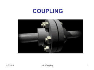
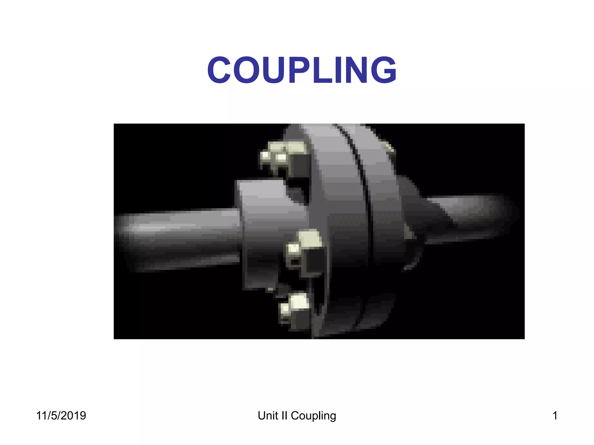
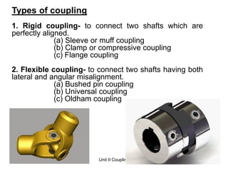
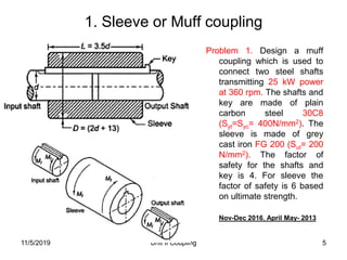
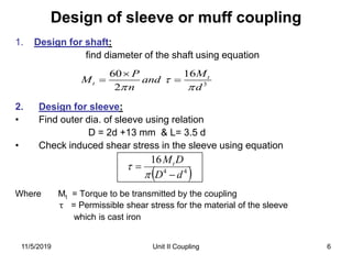
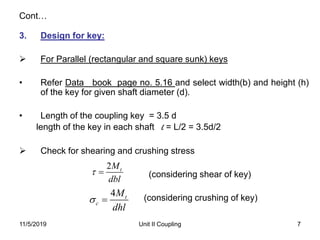
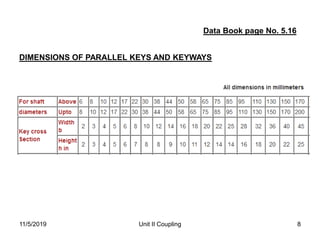
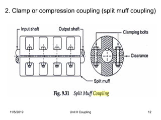
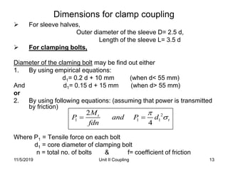
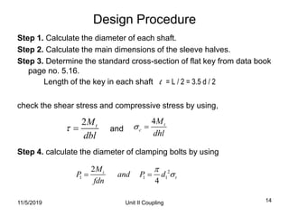
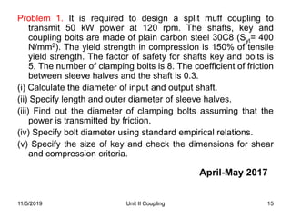
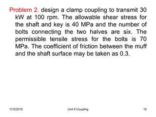
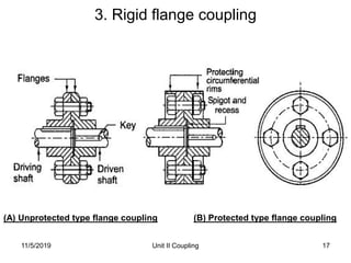
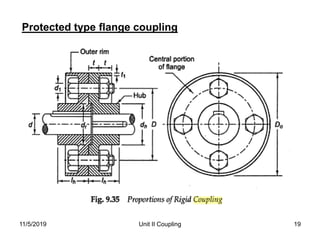
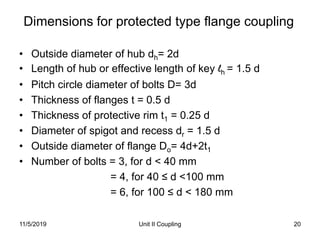
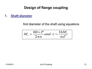
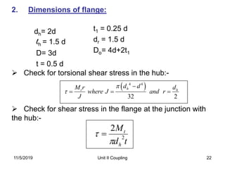
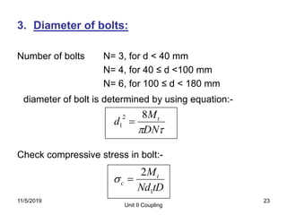
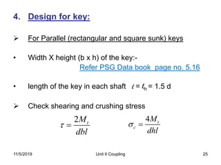
A coupling is a mechanical device that rigidly joins two rotating shafts together. There are three main types of couplings: rigid couplings for perfectly aligned shafts, flexible couplings for shafts with misalignment, and flange couplings which can transmit high torque capacities but do not tolerate misalignment or shocks/vibrations. Design of couplings involves calculating shaft diameters, sleeve/flange dimensions, key dimensions, and bolt diameters based on the transmitted power, material properties, and safety factors. Dimensional relationships and equations are used to check stresses in the various coupling components.
Unit 6- spur gears, Kinematics of machines of VTU Syllabus prepared by Hareesha N Gowda, Asst. Prof, Dayananda Sagar College of Engg, Blore. Please write to hareeshang@gmail.com for suggestions and criticisms.
This is a short description and some problems for the design of clutches.This also include the various classification in clutch and its description,use and also advantages of using these kinds of clutches.
It also includes a short view through different types of numerical problems which are solved for practising.
,
diploma mechanical engineering
,
mechanical engineering
,
machine design
,
design of machine elements
,
knuckle joint
,
failures of knuckle joint under different streses
,
fork end
,
single eye end
,
knuckle pin
Design of Flat belt, V belt and chain drivesDr. L K Bhagi
Geometrical relationships, Analysis of belt tensions, Condition for maximum power transmission, Characteristics of belt drives, Selection of flat belt, V- belt, Selection of V belt, Roller chains, Geometrical relationship, Polygonal effect, Power rating of roller chains, Design of chain drive, Introduction to belt drives and belt construction, Introduction to chain drives
This presentation contains basic idea regarding spur gear and provides the best equations for designing of spur gear. One can Easily understand all the parameters required to design a Spur Gear
ME010 801 Design of Transmission Elements
(Common with AU010 801)
Teaching scheme Credits: 4
2 hours lecture, 2 hour tutorial and 1 hour drawing per week
Objectives
To provide basic design skill with regard to various transmission elements like clutches, brakes, bearings and
gears.
Module I (20 Hrs)
Clutches - friction clutches- design considerations-multiple disc clutches-cone clutch- centrifugal clutch -
Brakes- Block brake- band brake- band and block brake-internal expanding shoe brake.
Module II (17 Hrs)
Design of bearings - Types - Selection of a bearing type - bearing life - Rolling contact bearings - static
and dynamic load capacity - axial and radial loads - selection of bearings - dynamic equivalent load -
lubrication and lubricants - viscosity - Journal bearings - hydrodynamic theory - design considerations -
heat balance - bearing characteristic number - hydrostatic bearings.
Module III (19 Hrs)
Gears- classification- Gear nomenclature - Tooth profiles - Materials of gears - design of spur, helical,
bevel gears and worm & worm wheel - Law of gearing - virtual or formative number of teeth- gear tooth
failures- Beam strength - Lewis equation- Buckingham’s equation for dynamic load- wear loadendurance strength of tooth- surface durability- heat dissipation - lubrication of gears - Merits and
demerits of each type of gears.
Module IV (16 Hrs)
Design of Internal Combustion Engine parts- Piston, Cylinder, Connecting rod, Flywheel
Design recommendations for Forgings- castings and welded products- rolled sections- turned parts,
screw machined products- Parts produced on milling machines. Design for manufacturing - preparation
of working drawings - working drawings for manufacture of parts with complete specifications including
manufacturing details.
Note: Any one of the following data book is permitted for reference in the final University examination:
1. Machine Design Data hand book by K. Lingaiah, Suma Publishers, Bangalore/ Tata Mc Graw Hill
2. PSG Design Data, DPV Printers, Coimbatore.
Text Books
1. C.S,Sarma, Kamlesh Purohit, Design of Machine Elements Prentice Hall of India Ltd NewDelhi
2. V.B.Bhandari, Design of Machine Elements McGraw Hill Book Company
3. M. F. Spotts, T. E. Shoup, Design of Machine Elements, Pearson Education.
Reference Books
1. J. E. Shigley, Mechanical Engineering Design, McGraw Hill Book Company.
2. Juvinall R.C & Marshek K.M., Fundamentals of Machine Component Design, John Wiley
3. Doughtie V.L., & Vallance A.V., Design of Machine Elements, McGraw Hill Book Company.
4. Siegel, Maleev & Hartman, Mechanical Design of Machines, International Book Company
The various forces acts on the reciprocating parts of an engine.
The resultant of all the forces acting on the body of the engine due to inertia forces only is known as unbalanced force or shaking force.
,
diploma mechanical engineering
,
mechanical engineering
,
machine design
,
design of machine elements
,
knuckle joint
,
failures of knuckle joint under different streses
,
fork end
,
single eye end
,
knuckle pin
Design of Flat belt, V belt and chain drivesDr. L K Bhagi
Geometrical relationships, Analysis of belt tensions, Condition for maximum power transmission, Characteristics of belt drives, Selection of flat belt, V- belt, Selection of V belt, Roller chains, Geometrical relationship, Polygonal effect, Power rating of roller chains, Design of chain drive, Introduction to belt drives and belt construction, Introduction to chain drives
This presentation contains basic idea regarding spur gear and provides the best equations for designing of spur gear. One can Easily understand all the parameters required to design a Spur Gear
ME010 801 Design of Transmission Elements
(Common with AU010 801)
Teaching scheme Credits: 4
2 hours lecture, 2 hour tutorial and 1 hour drawing per week
Objectives
To provide basic design skill with regard to various transmission elements like clutches, brakes, bearings and
gears.
Module I (20 Hrs)
Clutches - friction clutches- design considerations-multiple disc clutches-cone clutch- centrifugal clutch -
Brakes- Block brake- band brake- band and block brake-internal expanding shoe brake.
Module II (17 Hrs)
Design of bearings - Types - Selection of a bearing type - bearing life - Rolling contact bearings - static
and dynamic load capacity - axial and radial loads - selection of bearings - dynamic equivalent load -
lubrication and lubricants - viscosity - Journal bearings - hydrodynamic theory - design considerations -
heat balance - bearing characteristic number - hydrostatic bearings.
Module III (19 Hrs)
Gears- classification- Gear nomenclature - Tooth profiles - Materials of gears - design of spur, helical,
bevel gears and worm & worm wheel - Law of gearing - virtual or formative number of teeth- gear tooth
failures- Beam strength - Lewis equation- Buckingham’s equation for dynamic load- wear loadendurance strength of tooth- surface durability- heat dissipation - lubrication of gears - Merits and
demerits of each type of gears.
Module IV (16 Hrs)
Design of Internal Combustion Engine parts- Piston, Cylinder, Connecting rod, Flywheel
Design recommendations for Forgings- castings and welded products- rolled sections- turned parts,
screw machined products- Parts produced on milling machines. Design for manufacturing - preparation
of working drawings - working drawings for manufacture of parts with complete specifications including
manufacturing details.
Note: Any one of the following data book is permitted for reference in the final University examination:
1. Machine Design Data hand book by K. Lingaiah, Suma Publishers, Bangalore/ Tata Mc Graw Hill
2. PSG Design Data, DPV Printers, Coimbatore.
Text Books
1. C.S,Sarma, Kamlesh Purohit, Design of Machine Elements Prentice Hall of India Ltd NewDelhi
2. V.B.Bhandari, Design of Machine Elements McGraw Hill Book Company
3. M. F. Spotts, T. E. Shoup, Design of Machine Elements, Pearson Education.
Reference Books
1. J. E. Shigley, Mechanical Engineering Design, McGraw Hill Book Company.
2. Juvinall R.C & Marshek K.M., Fundamentals of Machine Component Design, John Wiley
3. Doughtie V.L., & Vallance A.V., Design of Machine Elements, McGraw Hill Book Company.
4. Siegel, Maleev & Hartman, Mechanical Design of Machines, International Book Company
The various forces acts on the reciprocating parts of an engine.
The resultant of all the forces acting on the body of the engine due to inertia forces only is known as unbalanced force or shaking force.
The purpose of this project is to compare the Normal Stresses induced in the Knuckle-Joint due to application of Tensile Force of 12KN by manual calculations and using Ansys Workbench. Also, to find minimum and maximum stress and Deformation in the Joint. In this report, Stresses found analytically are compared with the stresses found by the Analysis Software.
Design mini-project for TY mechanical studentsRavindra Shinde
In these project, we have designed a lifting table suitable to use in college . By adjusting the height of table any student can have proper sitting posture and position. It is also helpful for programmers/coders who have to seat for a long time, by having such a table they can do coding in a standing position too.
Bend Restrictors
Are present at the interface between flexible service lines (flexible flow-lines, umbilicals or cables) and rigid structures to prevent the over-bending of the service line during installation and service.
They are designed to be flexible but lock at a bend radius (MBR) greater than that of the service line, providing protection to the line from buckling or over bending.
Near neutrally buoyant half vertebra (shore 82D) are joined with corrosion resistant fasteners (UNS S32760).
Using extensive experience DGDG-EU have designed standard parts that comply with API 17J.
NO1 Uk best vashikaran specialist in delhi vashikaran baba near me online vas...Amil Baba Dawood bangali
Contact with Dawood Bhai Just call on +92322-6382012 and we'll help you. We'll solve all your problems within 12 to 24 hours and with 101% guarantee and with astrology systematic. If you want to take any personal or professional advice then also you can call us on +92322-6382012 , ONLINE LOVE PROBLEM & Other all types of Daily Life Problem's.Then CALL or WHATSAPP us on +92322-6382012 and Get all these problems solutions here by Amil Baba DAWOOD BANGALI
#vashikaranspecialist #astrologer #palmistry #amliyaat #taweez #manpasandshadi #horoscope #spiritual #lovelife #lovespell #marriagespell#aamilbabainpakistan #amilbabainkarachi #powerfullblackmagicspell #kalajadumantarspecialist #realamilbaba #AmilbabainPakistan #astrologerincanada #astrologerindubai #lovespellsmaster #kalajaduspecialist #lovespellsthatwork #aamilbabainlahore#blackmagicformarriage #aamilbaba #kalajadu #kalailam #taweez #wazifaexpert #jadumantar #vashikaranspecialist #astrologer #palmistry #amliyaat #taweez #manpasandshadi #horoscope #spiritual #lovelife #lovespell #marriagespell#aamilbabainpakistan #amilbabainkarachi #powerfullblackmagicspell #kalajadumantarspecialist #realamilbaba #AmilbabainPakistan #astrologerincanada #astrologerindubai #lovespellsmaster #kalajaduspecialist #lovespellsthatwork #aamilbabainlahore #blackmagicforlove #blackmagicformarriage #aamilbaba #kalajadu #kalailam #taweez #wazifaexpert #jadumantar #vashikaranspecialist #astrologer #palmistry #amliyaat #taweez #manpasandshadi #horoscope #spiritual #lovelife #lovespell #marriagespell#aamilbabainpakistan #amilbabainkarachi #powerfullblackmagicspell #kalajadumantarspecialist #realamilbaba #AmilbabainPakistan #astrologerincanada #astrologerindubai #lovespellsmaster #kalajaduspecialist #lovespellsthatwork #aamilbabainlahore #Amilbabainuk #amilbabainspain #amilbabaindubai #Amilbabainnorway #amilbabainkrachi #amilbabainlahore #amilbabaingujranwalan #amilbabainislamabad
Sachpazis:Terzaghi Bearing Capacity Estimation in simple terms with Calculati...Dr.Costas Sachpazis
Terzaghi's soil bearing capacity theory, developed by Karl Terzaghi, is a fundamental principle in geotechnical engineering used to determine the bearing capacity of shallow foundations. This theory provides a method to calculate the ultimate bearing capacity of soil, which is the maximum load per unit area that the soil can support without undergoing shear failure. The Calculation HTML Code included.
Overview of the fundamental roles in Hydropower generation and the components involved in wider Electrical Engineering.
This paper presents the design and construction of hydroelectric dams from the hydrologist’s survey of the valley before construction, all aspects and involved disciplines, fluid dynamics, structural engineering, generation and mains frequency regulation to the very transmission of power through the network in the United Kingdom.
Author: Robbie Edward Sayers
Collaborators and co editors: Charlie Sims and Connor Healey.
(C) 2024 Robbie E. Sayers
Student information management system project report ii.pdfKamal Acharya
Our project explains about the student management. This project mainly explains the various actions related to student details. This project shows some ease in adding, editing and deleting the student details. It also provides a less time consuming process for viewing, adding, editing and deleting the marks of the students.
Final project report on grocery store management system..pdfKamal Acharya
In today’s fast-changing business environment, it’s extremely important to be able to respond to client needs in the most effective and timely manner. If your customers wish to see your business online and have instant access to your products or services.
Online Grocery Store is an e-commerce website, which retails various grocery products. This project allows viewing various products available enables registered users to purchase desired products instantly using Paytm, UPI payment processor (Instant Pay) and also can place order by using Cash on Delivery (Pay Later) option. This project provides an easy access to Administrators and Managers to view orders placed using Pay Later and Instant Pay options.
In order to develop an e-commerce website, a number of Technologies must be studied and understood. These include multi-tiered architecture, server and client-side scripting techniques, implementation technologies, programming language (such as PHP, HTML, CSS, JavaScript) and MySQL relational databases. This is a project with the objective to develop a basic website where a consumer is provided with a shopping cart website and also to know about the technologies used to develop such a website.
This document will discuss each of the underlying technologies to create and implement an e- commerce website.
Explore the innovative world of trenchless pipe repair with our comprehensive guide, "The Benefits and Techniques of Trenchless Pipe Repair." This document delves into the modern methods of repairing underground pipes without the need for extensive excavation, highlighting the numerous advantages and the latest techniques used in the industry.
Learn about the cost savings, reduced environmental impact, and minimal disruption associated with trenchless technology. Discover detailed explanations of popular techniques such as pipe bursting, cured-in-place pipe (CIPP) lining, and directional drilling. Understand how these methods can be applied to various types of infrastructure, from residential plumbing to large-scale municipal systems.
Ideal for homeowners, contractors, engineers, and anyone interested in modern plumbing solutions, this guide provides valuable insights into why trenchless pipe repair is becoming the preferred choice for pipe rehabilitation. Stay informed about the latest advancements and best practices in the field.
Welcome to WIPAC Monthly the magazine brought to you by the LinkedIn Group Water Industry Process Automation & Control.
In this month's edition, along with this month's industry news to celebrate the 13 years since the group was created we have articles including
A case study of the used of Advanced Process Control at the Wastewater Treatment works at Lleida in Spain
A look back on an article on smart wastewater networks in order to see how the industry has measured up in the interim around the adoption of Digital Transformation in the Water Industry.
Courier management system project report.pdfKamal Acharya
It is now-a-days very important for the people to send or receive articles like imported furniture, electronic items, gifts, business goods and the like. People depend vastly on different transport systems which mostly use the manual way of receiving and delivering the articles. There is no way to track the articles till they are received and there is no way to let the customer know what happened in transit, once he booked some articles. In such a situation, we need a system which completely computerizes the cargo activities including time to time tracking of the articles sent. This need is fulfilled by Courier Management System software which is online software for the cargo management people that enables them to receive the goods from a source and send them to a required destination and track their status from time to time.
2. 2
Coupling
• Shafts are usually available up to 7 m length due to
inconvenience in transport. In order to have a greater length,
it becomes necessary to join two or more pieces of the shaft
by means of a coupling.
• A Coupling can be defined as a mechanical device that
rigidly joins two rotating shafts to each other.
• Uses:-
To Provide connections of shafts
To provide mechanical flexibility for misalignment of
shaft
To reduce transmission of shock loads from one shaft to
another shaft.
To introduce protection against overloads.
11/5/2019 Unit II Coupling
3. Unit II Coupling 3
Types of coupling
1. Rigid coupling- to connect two shafts which are
perfectly aligned.
(a) Sleeve or muff coupling
(b) Clamp or compressive coupling
(c) Flange coupling
2. Flexible coupling- to connect two shafts having both
lateral and angular misalignment.
(a) Bushed pin coupling
(b) Universal coupling
(c) Oldham coupling
11/5/2019
5. Unit II Coupling 5
1. Sleeve or Muff coupling
11/5/2019
Problem 1. Design a muff
coupling which is used to
connect two steel shafts
transmitting 25 kW power
at 360 rpm. The shafts and
key are made of plain
carbon steel 30C8
(Syt=Syc= 400N/mm2). The
sleeve is made of grey
cast iron FG 200 (Sut= 200
N/mm2). The factor of
safety for the shafts and
key is 4. For sleeve the
factor of safety is 6 based
on ultimate strength.
Nov-Dec 2016, April May- 2013
6. Unit II Coupling 6
Design of sleeve or muff coupling
1. Design for shaft:
find diameter of the shaft using equation
2. Design for sleeve:
• Find outer dia. of sleeve using relation
D = 2d +13 mm & L= 3.5 d
• Check induced shear stress in the sleeve using equation
Where Mt = Torque to be transmitted by the coupling
τ = Permissible shear stress for the material of the sleeve
which is cast iron
3
1660
2
t
t
MP
M and
n d
44
16
dD
DMt
11/5/2019
7. Unit II Coupling 7
Cont…
3. Design for key:
For Parallel (rectangular and square sunk) keys
• Refer Data book page no. 5.16 and select width(b) and height (h)
of the key for given shaft diameter (d).
• Length of the coupling key = 3.5 d
length of the key in each shaft l = L/2 = 3.5d/2
Check for shearing and crushing stress
(considering shear of key)
(considering crushing of key)
2 tM
dbl
4 t
c
M
dhl
11/5/2019
8. 11/5/2019 Unit II Coupling 8
Data Book page No. 5.16
DIMENSIONS OF PARALLEL KEYS AND KEYWAYS
9. Unit II Coupling 9
Problem 1. Design a muff coupling which is used to
connect two steel shafts transmitting 25 kW power at
360 rpm. The shafts and key are made of plain carbon
steel 30C8 (Syt=Syc= 400N/mm2). The sleeve is made of
grey cast iron FG 200 (Sut= 200 N/mm2). The factor of
safety for the shafts and key is 4. For sleeve the factor of
safety is 6 based on ultimate strength.
Nov-Dec 2016, April May- 2013
11/5/2019
10. Unit II Coupling 10
Problem 2. Design a rigid muff coupling. Use CI for
the muff. The power transmitted is 25 kW at 300
rpm. Ultimate tensile strength =200 MPa and
factor of safety =6. Use 30C8 for the shaft
considered. Yield Point stress = 330 Mpa and
factor of safety =4.
(April-May 2012, Nov- Dec 2013)
11/5/2019
11. Unit II Coupling 11
Problem 3. Design and make a neat dimensioned
sketch of a muff coupling, which is used to
connect two steel shafts transmitting 40 kW at
350 rpm. The material for the shaft and key is
plain carbon steel for which allowable shear and
crushing stresses may be taken as 40 MPa and
80 MPa respectively. The material for the muff is
cast iron for which the allowable shear stress
may be assumed 15 MPa.
(Nov-Dec 2012)
11/5/2019
12. Unit II Coupling 12
2. Clamp or compression coupling (split muff coupling)
11/5/2019
13. Unit II Coupling 13
Dimensions for clamp coupling
For sleeve halves,
Outer diameter of the sleeve D= 2.5 d,
Length of the sleeve L= 3.5 d
For clamping bolts,
Diameter of the claming bolt may be find out either
1. By using empirical equations:
d1= 0.2 d + 10 mm (when d< 55 mm)
And d1= 0.15 d + 15 mm (when d> 55 mm)
or
2. By using following equations: (assuming that power is transmitted
by friction)
Where P1 = Tensile force on each bolt
d1 = core diameter of clamping bolt
n = total no. of bolts & f= coefficient of friction
2
1 1 1
2
4
t
t
M
P and P d
fdn
11/5/2019
14. Unit II Coupling 14
Design Procedure
Step 1. Calculate the diameter of each shaft.
Step 2. Calculate the main dimensions of the sleeve halves.
Step 3. Determine the standard cross-section of flat key from data book
page no. 5.16.
Length of the key in each shaft l = L / 2 = 3.5 d / 2
check the shear stress and compressive stress by using,
and
Step 4. calculate the diameter of clamping bolts by using
2 tM
dbl
4 t
c
M
dhl
2
1 1 1
2
4
t
t
M
P and P d
fdn
11/5/2019
15. Unit II Coupling 15
Problem 1. It is required to design a split muff coupling to
transmit 50 kW power at 120 rpm. The shafts, key and
coupling bolts are made of plain carbon steel 30C8 (Syt= 400
N/mm2). The yield strength in compression is 150% of tensile
yield strength. The factor of safety for shafts key and bolts is
5. The number of clamping bolts is 8. The coefficient of friction
between sleeve halves and the shaft is 0.3.
(i) Calculate the diameter of input and output shaft.
(ii) Specify length and outer diameter of sleeve halves.
(iii) Find out the diameter of clamping bolts assuming that the
power is transmitted by friction.
(iv) Specify bolt diameter using standard empirical relations.
(v) Specify the size of key and check the dimensions for shear
and compression criteria.
11/5/2019
April-May 2017
16. Unit II Coupling 16
Problem 2. design a clamp coupling to transmit 30
kW at 100 rpm. The allowable shear stress for
the shaft and key is 40 MPa and the number of
bolts connecting the two halves are six. The
permissible tensile stress for the bolts is 70
MPa. The coefficient of friction between the muff
and the shaft surface may be taken as 0.3.
11/5/2019
17. Unit II Coupling 17
3. Rigid flange coupling
(A) Unprotected type flange coupling (B) Protected type flange coupling
11/5/2019
18. Advantages:-
1.High torque
transmitting capacity
2.Easy to assemble and
dismantle.
3.Simple construction,
easy to design and
manufacture.
Disadvantages:-
1.Does not tolerate
misalignment.
2.Unsuitable for shock
and vibration.
3.Requires more radial
spaces.
Unit II Coupling 1811/5/2019
20. Unit II Coupling 20
Dimensions for protected type flange coupling
• Outside diameter of hub dh= 2d
• Length of hub or effective length of key lh = 1.5 d
• Pitch circle diameter of bolts D= 3d
• Thickness of flanges t = 0.5 d
• Thickness of protective rim t1 = 0.25 d
• Diameter of spigot and recess dr = 1.5 d
• Outside diameter of flange Do= 4d+2t1
• Number of bolts = 3, for d < 40 mm
= 4, for 40 ≤ d <100 mm
= 6, for 100 ≤ d < 180 mm
11/5/2019
21. Design of flange coupling
Unit II Coupling 21
1. Shaft diameter
find diameter of the shaft using equations
3
1660
2
t
t
MP
M and
n d
11/5/2019
22. Unit II Coupling 22
2. Dimensions of flange:
dh= 2d
lh = 1.5 d
D= 3d
t = 0.5 d
Check for torsional shear stress in the hub:-
Check for shear stress in the flange at the junction with
the hub:-
t1 = 0.25 d
dr = 1.5 d
Do= 4d+2t1
td
M
h
t
2
2
4 4
32 2
ht h
d dM r d
where J and r
J
11/5/2019
23. 3. Diameter of bolts:
Number of bolts N= 3, for d < 40 mm
N= 4, for 40 ≤ d <100 mm
N= 6, for 100 ≤ d < 180 mm
diameter of bolt is determined by using equation:-
Check compressive stress in bolt:-
Unit II Coupling
23
DN
M
d t82
1
tDNd
Mt
c
1
2
11/5/2019
24. 11/5/2019 Unit II Coupling 24
THREADS FOR BOLTS AND NUTS
COARSE AND FINE SERIES
25. Unit II Coupling 25
4. Design for key:
For Parallel (rectangular and square sunk) keys
• Width X height (b x h) of the key:-
Refer PSG Data book page no. 5.16
• length of the key in each shaft l = lh = 1.5 d
Check shearing and crushing stress
2 tM
dbl
4 t
c
M
dhl
11/5/2019
26. Unit II Coupling 26
Problem 1. Design a cast iron protective type flange
coupling to transmit 15 kW at 900 rpm from an electric
motor to a compressor. The service factor may be
assumed as 1.35. The following permissible stresses
may be used:
Shear stress for shaft, bolt and key material = 40 MPa
Crushing stress for bolt and key = 80 MPa
Shear stress for cast iron = 8 MPa
Draw also a neat sketch of the coupling.
(April May 2015, Nov-Dec 2013)
11/5/2019
27. Unit II Coupling 27
Problem 2. Design and draw a protective type of
cast iron flange coupling for a steel shaft
transmitting 15 kW at 200 rpm and having an
allowable shear stress of 40 MPa. The working
stress in the bolts should not exceed 30 MPa.
Assume that the same material is used for shaft
and key and that the crushing stress is twice the
value of its shear stress. The maximum torque is
25% greater than the full load torque. The shear
stress for cast iron is 14 MPa. (2008 Supp.)
11/5/2019
28. Unit II Coupling 28
Problem 3. Two 35 mm shafts are connected by a flanged
coupling. The flanges are fitted with 6 bolts on 125 mm
pitch circle diameter of bolts. The shaft transmit a torque
of 800 N-m at 300 rpm. For the safe stresss mentioned
below calculate: (i) diameter of bolts (ii) thickness of
flanges (iii) Key dimensions (iv) hub length and (v) Power
transmitted
Safe shear stresses for shaft material = 63 MPa, Safe
shear stress for bolt material = 56 MPa, safe shear stress
for cast iron coupling = 10 MPa, Safe shear stress for key
material = 46 MPa
Also draw the line sketch of flange coupling.
(Nov-Dec 2011)
11/5/2019
29. Unit II Coupling 29
Problem 4. A rigid flange coupling is used to transmit 15
kW power at 720 rpm between two steel shaft. The shaft
key and bolt are made of plain carbon steel 30C8 (Syt=
400 N/mm2), FOS= 3. The yield strength in compression
may be taken as 150 % of tensile yield strength. The
flanges are made of grey cast iron of grade FG200 (Sut=
200 N/mm2), FOS= 6. The keys have square cross
section. Design a coupling and specify the dimensions of
its part.
11/5/2019
30. Unit II Coupling 30
Problem 5. A rigid flange coupling is required to transmit 50
kW at 300 rpm. There are six bolts. The outer diameter is of
flange is 200 mm and diameter of recess is 150 mm. The
coefficient of friction between the flanges is 0.15. The shaft
and bolt are made of plain carbon steel 45C8 (Syt= 380
N/mm2), fos= 3. Determine the diameter of the bolts.
Assume that the bolts are set in large clearance holes.
11/5/2019
36. 36
Step 1. Shaft diameter:-
Step 2 . Dimension of flange:-
• dh= outside diameter of hub= 2d
• lh= length of hub or effective length of key = 1.5d
• D= pitch circle diameter of pins= 3d to 4d
• t= thickness of output flanges = 0.5d
• t1= thickness of protective rim= 0.25d
• The torsional shear stress in the hub is given by-
Design procedure for flexible coupling
4 4
32 2
ht h
d dM r d
where J and r
J
11/5/2019 Unit II Coupling
37. Unit II Coupling 37
• The shear stress in the flange at the junction with the hub is given by:-
Step 3. Dimensions of bushes:-
• Outer diameter of rubber bush (Db) is determined from the equation.
• Where pm is pressure between bush and C.I. flange (usually 1N/mm2 )
• Effective length of the rubber bush lb= Db
Step 4. Diameter of Pins:-
• Diameter of pins , Number of pins (n) is usually 4 or 6.
• Determine the shear stress in the pins by,
11/5/2019
td
M
h
t
2
2
38. Unit II Coupling 38
Step 5. Check for bending stress in pins:
Torque transmitted by the coupling:
From above equation force P on each rubber bush or pin is determined.
Bending moment on the pin is given by:
Bending stress is checked by equation:
11/5/2019
39. Unit II Coupling 39
Step 6. Dimensions of keys:
Determine the standard cross-section of flat key from
data book page no. 5.16.
Length of the key l = length of hub = lh =1.5d
check the shear stress and compressive stress by using,
2 tM
dbl
4 t
c
M
dhl
11/5/2019
40. Unit II Coupling 40
Problem 1. A bushed pin type flexible coupling is used to
connect two shafts and transmit 5 kW power at 720 rpm.
Shafts, keys and pins are made of commercial steel
(Syt=Syc=240 N/mm2) and the factor of safety is 3. The flanges
are made of grey cast iron FG200 (Sut= 200 N/mm2) and the
factor of safety is 6. Assume
Ssy=0.5 Syt and Ssu= 0.5 Sut
There are 4 pins. The pitch circle diameter of the pins is four
times of shaft diameter. The permissible shear stress for pins
is 35 N/mm2. The bearing pressure for rubber bushing is 1
N/mm2. The keys have square cross section. Calculate:
(i) diameter of the shafts
(ii) dimensions of flange and hub
(iii) dimensions of the key
(iv) diameter of the pins
(v) outer diameter and effective length of the bushes.
11/5/2019
41. Unit II Basic Elements Design 41
Assignment-2
Que.1 Design a Knuckle joint (with fork and eye) to with stand a load of
10,000 N. The materials used for all components have the following
properties ultimate tensile strength = ultimate compressive strength
= 480 N/mm2. Shear strength = 360 N/mm2. Factor of safety =6.
After design, draw a neat proportioned sketch of joint giving all
dimensions.
Que.2 Design a cotter joint to carry a maximum load of 50,000 N. All
components are made of the same material having the following
allowable stresses. (Sleeve and cotter joint)
Tensile stress = 20 MN/m2
Compressive stress = 50 MN/m2
Shear stress = 15 MN/m2
Draw a proportioned neat sketch of the joint you have designed.
Que.3 It is required to design a square key for fixing a pulley on the
shaft which is 50 mm in diameter. A 10 kW power at 200 r.p.m. is
transmitted by the pulley to the shaft. The key is made of steel 45C8
(Syt= Syc= 380 N/mm2) and the factor of safety is 3. Determine the
dimensions of the key.
11/5/2019
42. 42
Que. 4 Design a C.I. flange coupling to transmit 150 H.P. at 250 rpm.
The following permissible stresses may be used:
Permissible shear stress for shaft, bolt and key material = 50 N/mm2
Permissible crushing stress for bolt and key material = 150 N/mm2
Permissible shear stress for Cast iron = 8 N/mm2
(Nov-Dec 2010)
Que.5 It is required to design a bushed pin type of flexible coupling for connecting
the motor to a centrifugal pump shafts. The details of the duty required from
the pump are:
Power to be transmitted = 18.5 kW
Speed in rpm = 1000
The diameters of the motor and pump shafts are 50 mm and 45 mm
respectively. Take the bearing pressure on the rubber bush as 0.35 N/mm2
and the working shear stress in the material of the pins as 20 N/mm2.
(2009)
11/5/2019 Unit II Coupling