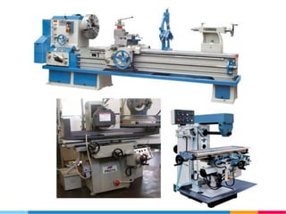
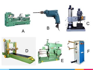
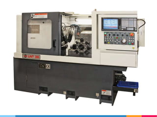
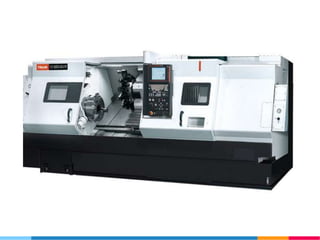
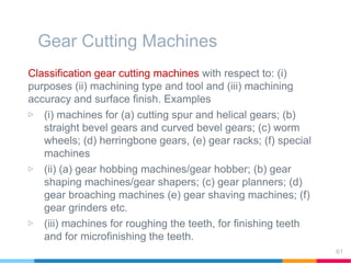
IPE-431 Machine Tools
Dr. Nafis Ahmad
Professor
Department of IPE, BUET
Email:nafis@ipe.buet.ac.bd
Topics
▷ Introduction
▷ Grinding Machines
▷ Micro-finishing Machines
▷ Gear Shaper/Shapping Machines
▷ Gear Hobber/ Hobing Machines
▷ Installation and acceptance tests of machine
tools etc.
▷ Other Important Topics
2
1.
Introduction to Machine
Tools
3
Contents
▷ Introduction
▷ Purpose of the course
▷ Course outcomes
▷ List of topics
▷ Lecture Plan
▷ Hand tools vs. Machine tools
▷ Examples of Machine tools
▷ Conclusions
4
Introduction
A machine tool is a machine for shaping or machining
metal or other rigid materials, usually by cutting, boring,
grinding, shearing, or other forms of deformation.
Machine tools employ some sort of tool that does the
cutting or shaping. All machine tools have some means of
constraining the workpiece and provide a guided
movement of the parts of the machine.
Thus the relative movement between the workpiece and
the cutting tool (which is called the toolpath) is controlled
or constrained by the machine to at least some extent,
rather than being entirely "offhand" or "freehand".
6
Introduction
Today machine tools are typically powered other than by
human muscle (e.g., electrically, hydraulically, or via line
shaft), used to make manufactured parts (components) in
various ways that include cutting or certain other kinds of
deformation.
True machine tools were born when the toolpath first
became guided by the machine itself in some way, at least
to some extent, so that direct, freehand human guidance
of the toolpath was no longer the only guidance used in
the cutting or forming process.
7
A
B
C
D
E
F
2.
Grinding Machine
11
Topics
▷ Introduction
▷ Type of grinding machines, grinding surfaces
▷ Movements in grinding operations
▷ Different parts of a grinding machine
▷ Specifications
▷ Working principle of different grinding machines
12
Introduction
A grinding machine, often
shortened to grinder, is any
of various power tools or
machine tools used for
grinding, which is a type of
machining using an
abrasive wheel as the
cutting tool. Each grain of
abrasive on the wheel's
surface cuts a small chip
from the workpiece via
shear deformation.
13
Introduction
Operations performed by grinding machines are:
 Grinding :
(a) external and internal cylindrical surfaces,
(b) tapered and complex-shaped surfaces,
(c) flat surfaces,
(d) screw threads,
(e) gear teeth
 Cutting off blanks
 Sharpening cutting tools
14
Introduction
15
Type of Grinding Machines
• Cylindrical grinding machine
• Centre-less grinding machine
• Internal grinding machine
• Surface grinders
• Special purpose grinding m/c
16
Type of grinding machines
Cylindrical grinding: generally used for generating external
cylindrical surfaces.
17
Grinding machines’ movements
Cylindrical grinder:
- rotation of the work piece (Swk in m/min)
- reciprocation of work table(S1 m/min or fraction of
grinding wheel width/rev of wp)
- intermittent cross movement of the grinding wheel
relative to w/p (cross feed or infeed S2 ) mm per double
stroke or sometimes single stroke.
18
Grinding machines’ movements
Cylindrical grinder with plung-cut principle:
- rotation of the work piece (Swk in m/min)
- infeed of the grinding wheel relative to w/p (cross feed or
infeed S1 )
- reciprocation of wheelhead/table(S2 m/min )
19
Grinding machines’ movements
Internal grinders:
- rotation of the work piece (circular feed Swk in m/min)
- reciprocation of workpiece or grinding wheel
(longitudinal feed S1 m/min )
- Intermittent cross movement of the wheel head (cross
feed S2 )
20
Grinding machines’ movements
Planetary grinders:
-rotation of the grinding wheel about the axis of the hole being
ground (circular feed Swh in m/min)
-reciprocation of workpiece or grinding wheel (longitudinal feed
S1 m/min )
- Intermittent cross movement of the wheel head (cross feed S2 )
21
Grinding machines’ movements
Surface grinders with rectangular
table:
- reciprocation of workpiece/table
(longitudinal feed Swk m/min )
- Intermittent cross movement of
the wheel head per stroke of
the table (cross feed S1 )
- Intermittent vertical movement,
or infeed S1 of the grinding
wheel to the depth of cut (
circular feed S2)
22
Grinding machines’ movements
Surface grinders with revolving
table:
- Circular feed of the table
Swk.
- Wheel or table feed S1
- Vertical movement of the
table or wheelhead is the
vertical feed S2.
23
Grinding machines’ movements
Vertical spindle surface grinders
with rectangular table: movements
- Longitudinal movement of the
table Swk.
- Wheel or table feed S1
- Intermittent vertical movement
of the grinding wheel to the
depth of cut S1.
24
Grinding machines’ movements
Vertical spindle surface grinders
with revolving table:
- Rotating movement of the
table S.
- Intermittent vertical
movement of the grinding
wheel to the depth of cut S1.
25
26
Case study-Cylindrical grinding
machine
Main specifications of a typical cylindrical grinding
machine (Model 3M151):
▷ Maximum dimension of workpiece accommodated (mm)
1. Diameter------------------------------------------- 200
2. Length-----------------------------------------------700
▷ Height from table top to centers (mm)------------125
▷ Range of workpiece rotation speed (rpm)------- 50-500
▷ Power of wheel drive motor, (kW) -----------------10
▷ Speed range of table traverse (m/min) ----------- 0.05-5
▷ Mass (Kg) ------------------------------------------------ 6032
27
Case study-Cylindrical grinding
machine
Cylindrical grinding machine (Model 3M151):
28
Case study-Cylindrical
grinding machine
Cylindrical grinding machine’s movements (Model 3M151):
Principle movement, Circular feed, Longitudinal feed, Cross
feed(infeed), Auxiliary movements
29
Case study-Cylindrical
grinding machine
Cylindrical grinding machine’s movements (Model 3M151):
▷ Principle movement -rotation of the grinding wheel
▷ Circular feed -rotation of the workpiece
▷ Longitudinal feed - straight reciprocating movement of the
work table.
▷ Cross feed(infeed) - intermittent radial displacement of the
wheelhead per stroke of the table
▷ Auxiliary movements – hand operated (a) longitudinal traverse
of the table, (b) cross feed of the wheelhead, (c) displacement
of the tailstock and (d) hydraulically-operated positioning
motion of the machine’s operative members
30
Cylindrical grinding machine’s kinematic diagram (Model 3M151):
31
Case study-Cylindrical
grinding machine
Cylindrical grinding machine’s working principle (Model 3M151):
▷ Workpiece is mounted between the centers of the workhead and
tailstock which are placed on the swiveling plate of the work
table.
▷ Grinding wheel is rotated by motor M2 through a V-belt drive
112/147.
▷ Circular feed or rotation of the workpiece is effected by a variable
d.c. motor M1 through V-belt transmission. Here
Swk=nm.0.985.i.pi.dw
▷ Cross feed/infeed mechanism provides (a) rapid positioning
movement of the wheelhead relative to the leadscrew, hand-
controlled/ automatically-controlled continuous and intermittent,
and periodical cross feed of the wheelhead
32
Case study-Cylindrical
grinding machine
Cylindrical grinding machine’s working principle(Model
3M151):
▷ Hand-controlled cross feed of the wheelhead is
effected from handwheel(1), magnetic clutch C1 being
engaged, through bevel gear 39/39, vertical shaft,
worm gearing 2/40 to the infeed screw-and-nut
transmission.
▷ Rapid positioning movement wheelhead is
accomplished from hydraulic motor M3, with magnetic
clutch C1 being disengaged. Motion is transmitted
from the shaft of the motor through a pair of cylindrical
gears 35/35, bevel gearing 39/39, and further, to the
infeed leadscrew.
33
Case study cont..
Cylindrical grinding machine’s working principle(Model
3M151):
▷ Automatically controlled intermittent feeds to
wheelhead are powered by hydraulic motor m4, with
magnetic clutch C2 engaged, through worm gearing
1/50, handwheel , clutch C1, bevel gearing 39/39, and
further to the infeed lead screw.
▷ Automatically controlled periodic feed to wheelheads:
are performed by a gear train described above. Here
magnetic clutch is engaged for a specific period of
motion and is then disengaged, stopping the motion of
worm gearing 1/50.
▷ Draw block diagrams for the above mechanisms
mentioning motor/handwheel/shaft/gears/leadsrew etc.:
34
Case study-Cylindrical
grinding machine
Functions of cylindrical grinding machine’s hydraulic drive (Model
3M151):
▷ Work table: reversible traverse of the work table at a working
speed or variable speed; oscillating motion of the table.
▷ Wheel head: Rapid advance and retraction of wheelhead; cross
travel of the wheelhead; continuous cross feed of the wheelhead;
continuous infeed of the wheelhead; automatic withdrawal of
wheelhead
▷ Tailstock: Withdrawal of tailstock spindle
▷ Interlocking of hand operated table motion mechanism
▷ Motions of the diamond dresser
▷ Supply of lubricant to spindle bearing, infeed leadscrew bearings
and worktable guideways
35
Case study-Cylindrical
grinding machine
Cylindrical grinding machine’s working principle (Model 3M151):
▷ Write short notes on the mechanisms of
a) Automatically controlled periodic feed to wheelheads
36
Surface grinding machine
37
Case study-Surface grinding
machine
Surface grinding machine types:
38
Spindle Table Column Special
Horizontal Reciprocating/
rectangular
Horizontal reciprocating universal
Vertical reciprocating
Horizontal rotary
Movable Single, Movable Planner type
Double,
movable
Planner type
Surface grinding machine-case study
39
Surface grinding machine-case study
40
Generap purpose surface grinding machine’s working principle :
▷ 1- Cast Bed, 2-Wheelhead, 3-Column of rigid cast frame with a
through opening at the middle, 4-vertical guide ways which carry
the wheelhead, 5-Cabinet contains hydraulic station and
electrical equipment
▷ Table reciprocates along the bed with the help from two hydraulic
cylinders.
▷ Two speed motor provide wheel speed up to 70m/s. Wheelhead
moves vertically by hand or automatic downfeed mechanism,
mounted on the front wall of the bed. Rapid traverse is effected
by a mechanism mounted on the rear wall of the column.
Centerless grinding machine
41
1-External and internal surfaces of cylindrical parts having no central
holes can be ground on centerless grinding machines:
 Through-feed centerless grinding
Centerless grinding machine
42
2.2
Micro-finishing Machines
43
Microfinishing Machines
▷ Intended for final machining of
workpieces.
▷ Most widely used machines are:
▷ Lapping
▷ Honing
▷ Superfinishing
44
Lapping
▷ Lapping is done by tools called laps
▷ Lap surface is charged with fine-grained abrasive flour
mixed with oil and paste.
▷ Laps are made of cast iron, steel bronze etc.
▷ Crank shaft, gears, gauge block etc. are machined
45
Lapping
 Abrasive flours: diamond
dust, silicon arbide etc.
 Paste: chromium oxide,
aluminium oxide etc.
 Kerosine or turpentine is
used to wet the flour
 Machining allowance:
0.005~0.02mm
46
Lapping Machine
1-Bed, Column, 3,5-Lap, 4-work retainer
47
Lapping Machine
• Spindle 5 and lap 2 is
driven by motor(7.8kW)
through V-belt drive
150/375, worm gearing
4/40, cardan shaft II, and V-
belt drive 320/352
• Lap-1 get rotational
movement from the same
motor through shaft III and
worm gearing 4/40 and
sleev 8
48
Lapping Machine
• For flat surface: forced
oscillation is imparted
to the retainer by
means of crank pin(3)
secured in disc(7)
• Disc-7 is driven from
shaft-III through worm
gearing 4/40 and
cylindrical gears
40/80x34/86 and shaft
I
49
Lapping Machine
• For cylindrical surface
lapping:: the retainer is
kept motionless by
disengaging clutch-9
• Hydraulic mechanism-
used for approach and
pressing lap-2 to the
workpiece being
lapped. Cylinders-4
and 6, piston rod
connected to the
holder of lap 2 are part
of hydraulic system
50
Honing Machine
• Honing is accomplished with a
special tool called hone, which is
equipped with fine-grained
abrasive sticks(4)
• Simultaneously rotating and
reciprocating movement in the
hole being honed
• High class surface finish, correct
shape deviations like taper, out of
roundness etc.
• Kerosene is used as cutting fluid
51
Honing Machine
• Abrasive stick(4) receive radial
displacement by cones(2,5)
mounted on screw-threaded
rod(3)
• After each double stroke of hone,
rod(3) is turned and draws cones
2 and 5 closer together
52
Honing Machine
• In Fig.15-18 rotation of the
spindle is done by an electric
motor(3) through the speed gear
box.
• Reciprocating movement of the
spindle is accomplished by
means of a hydraulic drive
53
Superfinishing Machines
• Super finishing is employed
to machine external and
internal cylindrical
surfaces for obtaining the
highest surface finish.
• Abrasive stick oscillates
and reciprocates with high
frequency and low
amplitude along the
surface of the workpiece
• Mixture of kerosene and oil
is used as cutting fluid
54
Superfinishing Machines
• Workpiece is mounted
between centers of
headstock(1) and tailstock(4)
• W/p rotation from dog drive
plate-2,
• Abrasive sticks are clamped in
special holders(3)
• Hydraulic drive imparts
reciprocating movement of
abrasive stick along wp
surface.
55
3.
Gear Cutting Machines
56
Gear Cutting Machines
▷ Introduction
▷ Form cutting vs. Generating
▷ Classification gear cutting machines
with respect to: (i) purposes (ii)
machining type and tool and (iii)
machining accuracy and surface
finish
▷ Case study of a Gear shaper
▷ Case study of a Gear hobbing
machine
57
Gear cutting
58
Introduction
Depending on the principle of tooth-flank forming, gear
cutting is mainly performed by form cutting and generating
methods.
Form cutting: each tooth space on the gear blank is
machined by a cutting tool whose cutting-edge shape is
identical with the tooth-space shape of the gear being
machined. Slow process. Milling machines are used.
Generating method: the tool cutting edges take a series of
successive positions relative to the gear tooth profiles. High
productive output and accuracy of gear being cut are
the key features of this method. Rack type cutter, gear
hobs and rotary shaping cutters are used.
59
Gear Cutting
60
Gear Cutting Machines
Classification gear cutting machines with respect to: (i)
purposes (ii) machining type and tool and (iii) machining
accuracy and surface finish. Examples
▷ (i) machines for (a) cutting spur and helical gears; (b)
straight bevel gears and curved bevel gears; (c) worm
wheels; (d) herringbone gears, (e) gear racks; (f) special
machines
▷ (ii) (a) gear hobbing machines/gear hobber; (b) gear
shaping machines/gear shapers; (c) gear planners; (d)
gear broaching machines (e) gear shaving machines; (f)
gear grinders etc.
▷ (iii) machines for roughing the teeth, for finishing teeth
and for microfinishing the teeth.
61
Case study- Gear shaper (5122)
External, internal spar gear,
gear cluster and helical gears
can be cut using this machine.
Parts are: 1-Bed, 2-circular
scale, 3-work table,4-square
end, 5-Door, 6-circular feed
gearbox, 7-ram slide, 8-control
panel, 9-column, 10-removable
cover, 11-door, 12-intermediate
frame, 13-switch gear cabinet,
14-hydraulic station
62
Gear shaper
Movements in a typical gear
shaper:
▷ I-Reciprocating movement of
the cutter
▷ II-Gear blank rotation
▷ III-Circular feed of the cutter
▷ IV-Radial infeed
▷ V-withdrawal movement of the
cutter
64
Gear shaper
65
Case study- Gear shaper (5122)
Specifications:
1. Maximum diameter of gear cut, mm ---------------------- 200
2. Maximum facewidth, mm ------------------------------------ 50
3. Maximum module, mm --------------------------------------- 5
4. Nominal diameter of gear-shaper cutter, mm -----------100
5. Number of cutter double strokes per min -----------200-800
6. Feed rate per double stroke, mm
Circular ----- 0.16-1.6
Radial-----------0.003-0.286
7. Main drive motor power, kW -------------------------------- 2.1/3
8. Mass, t ---------------------------------------------------------- 4.4
66
Case study- Gear shaper (5122)
67
Case study- Gear shaper (5122)
Movements:
• Reciprocation of the cutter-
• Circular feed (rotation of the cutter)-(i) coarse-feed
train and (ii) finish feed train
• Gear blank rotation (indexing motion)
Write the kinematic balance equations for the
movements and find different values of speed/feed rates.
Assignment: Mechanism of cutting helical gears using
gear shaper.
68
Case study- Gear shaper (5122)
Movements: Reciprocation of the cutter
69
Motor M
V-belt Drive
D1/D2
Driving Shaft
Link Gear 1
Cutter Spindle
Case study- Gear shaper (5122)
Movements: Reciprocation of the
cutter
If for a specific tool-workpiece
combination, maximum cutting
speed is 100m/min. Which one of
the motor rpms (840/1440) should
we select? Assume that facewidth
of the gear blank is 90mm and
over travel of the cutter is 10mm.
Here, D1=200mm and D2=400mm
70
Case study- Gear shaper (5122)
Movements:Circular feed (rotation of the cutter)-(i) coarse-
feed train and (ii) finish feed train
Here, 1 double stroke of cutter  Circular feed/double stroke
Kinematic balance equation (coarse feed)
What will be the kinematic balance equation for finish feed?
What will be the circular feed if a=b=c=d=50, zct=42 and
m=10.
71
Case study- Gear shaper (5122)
Movements:Gear blank rotation (indexing motion)
Here, Movement of 1 tooth of cuttermovement of 1 tooth
of g/b
Kinematic balance equation
So, formula for indexing gear train setup is:
72
Case study- Gear shaper (5122)
Mechanism for cutting helical gears:
Cutter: rotary gear shaper cutter having
helical teeth
Helical guideways with a lead equal to that of
the cutter tooth helix mounted on a ram slide
Guideways consist of a movable part secured
to the cutter spindle and a stationary one
mounted in the hub of worm z=90
Stationary part rotates with worm wheel
Movable part receives a forced additional
rotation together with the cutter spindle.
73
Gear Hobbing Methods
Gear hob removes materials from the
gear blank to produce cylindrical gears.
When being machined, the gear blank
is in mesh with a moving imaginary
generating rack which is reproduced in
the space with the cutting edges of the
gear hob in its rotating and straight
movements.
For spur gear, the blank should make
Z/z revolutions during one revolution of
Z-start hob
To extend the form of the teeth along
the gear width, a straight movement
along the blank axis is imparted to the
hob simulteniously with its rotation
74
Gear Hobbing Methods
The hob axis being horizontal, one of
the teeth is set to the work table centre
in order to obtain correct profile of the
tooth.
The hob axis should be inclined to the
gear blank face at the lead angle of the
hob thread.
For helical gears, the hob axis is to be
inclined at an angle of
δ = β±λ
Here, β helix angle of the gear to be
cut, λ lead angle of hob thread
75
Gear Hobbing Methods
For helical gears, the hob axis
is to be inclined at an angle of
δ = β±λ
Here, β helix angle of the gear
to be cut, λ lead angle of hob
thread
“+” for different helix hands of
of the gear to be cut and the
hob.
“-” for the same hands
76
4.
Installation and Acceptance
Tests of Machine Tools
78
Gear Cutting Machines
▷ Introduction
▷ Installing and securing machine tools
▷ Machine tool tests
▷ Accuracy checking
79
Introduction
Effective and highly productive operation of an industrial
enterprise can be ensured by organizing and properly using the
equipment. As a result accuracy over a long periods of time can
also be ensured. Proper use of machine tools involves:
i) Appropriate packing-prevent damage to machine tools
ii) Transportation
iii) Correct installation of machine tools to ensure trouble free
operation
iv) Servicing-cleaning, lubricating, selection of coolant,
collection and restoration of used lubricant/coolant etc
v) Repair-timely and proper repairs essential for rhythmic
operation of plants
vi) Aging machine tools should underga modernization, which
extend their service life to ultimate obsolescence etc.
80
Foundation of machine tools
In order for machine tools to perform at their full design capability
and deliver many years of profitable service, designing and
building good foundation is extremely important. Installation of
machine tool on a foundation affects its performance
characteristics. Types of foundation used most frequently are: a)
ground floor of concrete, b) a concrete strip-type foundation, c) a
specially designed massive foundation, d) a pile supported
foundation, e) a vibration proof foundation resting on rubber
mats and f) foundation resting on spring
81
Foundation of machine tools
82
Securing machine tools
Machine tools are set on foundation as follows: by bolting the
bed placed on adjustable screw- or wedge-type supports with or
without grouting to the foundation, without bolting, but with
grouting; with neither bolting nor grouting, the bed resting on
solid adjustable metal supports or on elastic (e.g. rubber-metal)
supports.
83
General Recommendations
Knee-and-bed-type milling machines:
• Installation with bolting- Stationary machines for various jobs
(roughing included). Machines operating under severe
conditions.
• Without bolting, with grouting- Main part of infrequently
relocated machines; relocated machines under severe
conditions
• With bolting or grouting- Frequently relocated machines
under severe conditions.
• On elastic supports- Machines installed in insufficiently rigid
floor; frequently relocated machines working in average and
light operating conditions
84
General Recommendations
Engine and turret lathe machines:
• Installation with bolting- Stationary machines for various jobs
(roughing included) at impact loads, for imbalanced workpieces.
Long bed machines used under severe operating conditions.
• Without bolting, with grouting- Infrequently relocated or long-bed
machines working under average operating conditions
• With bolting or grouting- Frequently relocated machines with
relatively short beds. For higher rigidity, bed legs can be tied
together by means of intermediate metal frame.
• On elastic supports- Relatively small machines (D </= 400mm;
distance between centers under 1000 mm), frequently relocated
and used for machining balanced workpieces under average
operating conditions. Placed on in-sufficiently rigid floor or highly
oscillating base.
85
Machine Tool Acceptance Tests
After manufacture or repairs, each machine tool should meet
the requirements of specifications. Acceptance test of
machine tool should include:
• Idle run tests, mechanisms operation checks, certificate
data check
• Load tests and productive output tests
• Check of geometrical accuracy, surface roughness, and
the accuracy of the surface being machined
• Rigidity tests of machine tools
• Tests for vibration-proof properties of machine tools in
cutting
86
Accuracy checks
Accuracy checks are: machine tools geometrical accuracy,
the accuracy of the workpiece machined and its surface
roughness. Checking of the machine tools geometrical
accuracy which includes:
• checking the guideways for straightness;
• work table for flatness;
• column, uprights, and baseplates for deviation from the
vertical and horizontal plans;
• Spindles for correct location and accuracy of rotation;
• Relative position of axes and surfaces for parallelism and
squarness;
• Leadscrews and indexing devices for specific errors.
87
Accuracy checks
• Accuracy checks of machine tools also includes machining
work samples including a check of their surface
roughness. These test should be carried out after the
preliminary idle running of the machine tool or its load test,
with essential parts of the machine having a stabilized
working temperature.
• The kid of work sample, its material, and the character of
machining for various types of machine tools
Thanks
88
Thanks!
Any questions?
You can find me at:
@ahmadn
nafis@ipe.buet.ac.bd
89

IPE-431 Machine Tools (Part-C)

  • 1.
    IPE-431 Machine Tools Dr.Nafis Ahmad Professor Department of IPE, BUET Email:nafis@ipe.buet.ac.bd
  • 2.
    Topics ▷ Introduction ▷ GrindingMachines ▷ Micro-finishing Machines ▷ Gear Shaper/Shapping Machines ▷ Gear Hobber/ Hobing Machines ▷ Installation and acceptance tests of machine tools etc. ▷ Other Important Topics 2
  • 3.
  • 4.
    Contents ▷ Introduction ▷ Purposeof the course ▷ Course outcomes ▷ List of topics ▷ Lecture Plan ▷ Hand tools vs. Machine tools ▷ Examples of Machine tools ▷ Conclusions 4
  • 6.
    Introduction A machine toolis a machine for shaping or machining metal or other rigid materials, usually by cutting, boring, grinding, shearing, or other forms of deformation. Machine tools employ some sort of tool that does the cutting or shaping. All machine tools have some means of constraining the workpiece and provide a guided movement of the parts of the machine. Thus the relative movement between the workpiece and the cutting tool (which is called the toolpath) is controlled or constrained by the machine to at least some extent, rather than being entirely "offhand" or "freehand". 6
  • 7.
    Introduction Today machine toolsare typically powered other than by human muscle (e.g., electrically, hydraulically, or via line shaft), used to make manufactured parts (components) in various ways that include cutting or certain other kinds of deformation. True machine tools were born when the toolpath first became guided by the machine itself in some way, at least to some extent, so that direct, freehand human guidance of the toolpath was no longer the only guidance used in the cutting or forming process. 7
  • 8.
  • 11.
  • 12.
    Topics ▷ Introduction ▷ Typeof grinding machines, grinding surfaces ▷ Movements in grinding operations ▷ Different parts of a grinding machine ▷ Specifications ▷ Working principle of different grinding machines 12
  • 13.
    Introduction A grinding machine,often shortened to grinder, is any of various power tools or machine tools used for grinding, which is a type of machining using an abrasive wheel as the cutting tool. Each grain of abrasive on the wheel's surface cuts a small chip from the workpiece via shear deformation. 13
  • 14.
    Introduction Operations performed bygrinding machines are:  Grinding : (a) external and internal cylindrical surfaces, (b) tapered and complex-shaped surfaces, (c) flat surfaces, (d) screw threads, (e) gear teeth  Cutting off blanks  Sharpening cutting tools 14
  • 15.
  • 16.
    Type of GrindingMachines • Cylindrical grinding machine • Centre-less grinding machine • Internal grinding machine • Surface grinders • Special purpose grinding m/c 16
  • 17.
    Type of grindingmachines Cylindrical grinding: generally used for generating external cylindrical surfaces. 17
  • 18.
    Grinding machines’ movements Cylindricalgrinder: - rotation of the work piece (Swk in m/min) - reciprocation of work table(S1 m/min or fraction of grinding wheel width/rev of wp) - intermittent cross movement of the grinding wheel relative to w/p (cross feed or infeed S2 ) mm per double stroke or sometimes single stroke. 18
  • 19.
    Grinding machines’ movements Cylindricalgrinder with plung-cut principle: - rotation of the work piece (Swk in m/min) - infeed of the grinding wheel relative to w/p (cross feed or infeed S1 ) - reciprocation of wheelhead/table(S2 m/min ) 19
  • 20.
    Grinding machines’ movements Internalgrinders: - rotation of the work piece (circular feed Swk in m/min) - reciprocation of workpiece or grinding wheel (longitudinal feed S1 m/min ) - Intermittent cross movement of the wheel head (cross feed S2 ) 20
  • 21.
    Grinding machines’ movements Planetarygrinders: -rotation of the grinding wheel about the axis of the hole being ground (circular feed Swh in m/min) -reciprocation of workpiece or grinding wheel (longitudinal feed S1 m/min ) - Intermittent cross movement of the wheel head (cross feed S2 ) 21
  • 22.
    Grinding machines’ movements Surfacegrinders with rectangular table: - reciprocation of workpiece/table (longitudinal feed Swk m/min ) - Intermittent cross movement of the wheel head per stroke of the table (cross feed S1 ) - Intermittent vertical movement, or infeed S1 of the grinding wheel to the depth of cut ( circular feed S2) 22
  • 23.
    Grinding machines’ movements Surfacegrinders with revolving table: - Circular feed of the table Swk. - Wheel or table feed S1 - Vertical movement of the table or wheelhead is the vertical feed S2. 23
  • 24.
    Grinding machines’ movements Verticalspindle surface grinders with rectangular table: movements - Longitudinal movement of the table Swk. - Wheel or table feed S1 - Intermittent vertical movement of the grinding wheel to the depth of cut S1. 24
  • 25.
    Grinding machines’ movements Verticalspindle surface grinders with revolving table: - Rotating movement of the table S. - Intermittent vertical movement of the grinding wheel to the depth of cut S1. 25
  • 26.
  • 27.
    Case study-Cylindrical grinding machine Mainspecifications of a typical cylindrical grinding machine (Model 3M151): ▷ Maximum dimension of workpiece accommodated (mm) 1. Diameter------------------------------------------- 200 2. Length-----------------------------------------------700 ▷ Height from table top to centers (mm)------------125 ▷ Range of workpiece rotation speed (rpm)------- 50-500 ▷ Power of wheel drive motor, (kW) -----------------10 ▷ Speed range of table traverse (m/min) ----------- 0.05-5 ▷ Mass (Kg) ------------------------------------------------ 6032 27
  • 28.
    Case study-Cylindrical grinding machine Cylindricalgrinding machine (Model 3M151): 28
  • 29.
    Case study-Cylindrical grinding machine Cylindricalgrinding machine’s movements (Model 3M151): Principle movement, Circular feed, Longitudinal feed, Cross feed(infeed), Auxiliary movements 29
  • 30.
    Case study-Cylindrical grinding machine Cylindricalgrinding machine’s movements (Model 3M151): ▷ Principle movement -rotation of the grinding wheel ▷ Circular feed -rotation of the workpiece ▷ Longitudinal feed - straight reciprocating movement of the work table. ▷ Cross feed(infeed) - intermittent radial displacement of the wheelhead per stroke of the table ▷ Auxiliary movements – hand operated (a) longitudinal traverse of the table, (b) cross feed of the wheelhead, (c) displacement of the tailstock and (d) hydraulically-operated positioning motion of the machine’s operative members 30
  • 31.
    Cylindrical grinding machine’skinematic diagram (Model 3M151): 31
  • 32.
    Case study-Cylindrical grinding machine Cylindricalgrinding machine’s working principle (Model 3M151): ▷ Workpiece is mounted between the centers of the workhead and tailstock which are placed on the swiveling plate of the work table. ▷ Grinding wheel is rotated by motor M2 through a V-belt drive 112/147. ▷ Circular feed or rotation of the workpiece is effected by a variable d.c. motor M1 through V-belt transmission. Here Swk=nm.0.985.i.pi.dw ▷ Cross feed/infeed mechanism provides (a) rapid positioning movement of the wheelhead relative to the leadscrew, hand- controlled/ automatically-controlled continuous and intermittent, and periodical cross feed of the wheelhead 32
  • 33.
    Case study-Cylindrical grinding machine Cylindricalgrinding machine’s working principle(Model 3M151): ▷ Hand-controlled cross feed of the wheelhead is effected from handwheel(1), magnetic clutch C1 being engaged, through bevel gear 39/39, vertical shaft, worm gearing 2/40 to the infeed screw-and-nut transmission. ▷ Rapid positioning movement wheelhead is accomplished from hydraulic motor M3, with magnetic clutch C1 being disengaged. Motion is transmitted from the shaft of the motor through a pair of cylindrical gears 35/35, bevel gearing 39/39, and further, to the infeed leadscrew. 33
  • 34.
    Case study cont.. Cylindricalgrinding machine’s working principle(Model 3M151): ▷ Automatically controlled intermittent feeds to wheelhead are powered by hydraulic motor m4, with magnetic clutch C2 engaged, through worm gearing 1/50, handwheel , clutch C1, bevel gearing 39/39, and further to the infeed lead screw. ▷ Automatically controlled periodic feed to wheelheads: are performed by a gear train described above. Here magnetic clutch is engaged for a specific period of motion and is then disengaged, stopping the motion of worm gearing 1/50. ▷ Draw block diagrams for the above mechanisms mentioning motor/handwheel/shaft/gears/leadsrew etc.: 34
  • 35.
    Case study-Cylindrical grinding machine Functionsof cylindrical grinding machine’s hydraulic drive (Model 3M151): ▷ Work table: reversible traverse of the work table at a working speed or variable speed; oscillating motion of the table. ▷ Wheel head: Rapid advance and retraction of wheelhead; cross travel of the wheelhead; continuous cross feed of the wheelhead; continuous infeed of the wheelhead; automatic withdrawal of wheelhead ▷ Tailstock: Withdrawal of tailstock spindle ▷ Interlocking of hand operated table motion mechanism ▷ Motions of the diamond dresser ▷ Supply of lubricant to spindle bearing, infeed leadscrew bearings and worktable guideways 35
  • 36.
    Case study-Cylindrical grinding machine Cylindricalgrinding machine’s working principle (Model 3M151): ▷ Write short notes on the mechanisms of a) Automatically controlled periodic feed to wheelheads 36
  • 37.
  • 38.
    Case study-Surface grinding machine Surfacegrinding machine types: 38 Spindle Table Column Special Horizontal Reciprocating/ rectangular Horizontal reciprocating universal Vertical reciprocating Horizontal rotary Movable Single, Movable Planner type Double, movable Planner type
  • 39.
  • 40.
    Surface grinding machine-casestudy 40 Generap purpose surface grinding machine’s working principle : ▷ 1- Cast Bed, 2-Wheelhead, 3-Column of rigid cast frame with a through opening at the middle, 4-vertical guide ways which carry the wheelhead, 5-Cabinet contains hydraulic station and electrical equipment ▷ Table reciprocates along the bed with the help from two hydraulic cylinders. ▷ Two speed motor provide wheel speed up to 70m/s. Wheelhead moves vertically by hand or automatic downfeed mechanism, mounted on the front wall of the bed. Rapid traverse is effected by a mechanism mounted on the rear wall of the column.
  • 41.
    Centerless grinding machine 41 1-Externaland internal surfaces of cylindrical parts having no central holes can be ground on centerless grinding machines:  Through-feed centerless grinding
  • 42.
  • 43.
  • 44.
    Microfinishing Machines ▷ Intendedfor final machining of workpieces. ▷ Most widely used machines are: ▷ Lapping ▷ Honing ▷ Superfinishing 44
  • 45.
    Lapping ▷ Lapping isdone by tools called laps ▷ Lap surface is charged with fine-grained abrasive flour mixed with oil and paste. ▷ Laps are made of cast iron, steel bronze etc. ▷ Crank shaft, gears, gauge block etc. are machined 45
  • 46.
    Lapping  Abrasive flours:diamond dust, silicon arbide etc.  Paste: chromium oxide, aluminium oxide etc.  Kerosine or turpentine is used to wet the flour  Machining allowance: 0.005~0.02mm 46
  • 47.
    Lapping Machine 1-Bed, Column,3,5-Lap, 4-work retainer 47
  • 48.
    Lapping Machine • Spindle5 and lap 2 is driven by motor(7.8kW) through V-belt drive 150/375, worm gearing 4/40, cardan shaft II, and V- belt drive 320/352 • Lap-1 get rotational movement from the same motor through shaft III and worm gearing 4/40 and sleev 8 48
  • 49.
    Lapping Machine • Forflat surface: forced oscillation is imparted to the retainer by means of crank pin(3) secured in disc(7) • Disc-7 is driven from shaft-III through worm gearing 4/40 and cylindrical gears 40/80x34/86 and shaft I 49
  • 50.
    Lapping Machine • Forcylindrical surface lapping:: the retainer is kept motionless by disengaging clutch-9 • Hydraulic mechanism- used for approach and pressing lap-2 to the workpiece being lapped. Cylinders-4 and 6, piston rod connected to the holder of lap 2 are part of hydraulic system 50
  • 51.
    Honing Machine • Honingis accomplished with a special tool called hone, which is equipped with fine-grained abrasive sticks(4) • Simultaneously rotating and reciprocating movement in the hole being honed • High class surface finish, correct shape deviations like taper, out of roundness etc. • Kerosene is used as cutting fluid 51
  • 52.
    Honing Machine • Abrasivestick(4) receive radial displacement by cones(2,5) mounted on screw-threaded rod(3) • After each double stroke of hone, rod(3) is turned and draws cones 2 and 5 closer together 52
  • 53.
    Honing Machine • InFig.15-18 rotation of the spindle is done by an electric motor(3) through the speed gear box. • Reciprocating movement of the spindle is accomplished by means of a hydraulic drive 53
  • 54.
    Superfinishing Machines • Superfinishing is employed to machine external and internal cylindrical surfaces for obtaining the highest surface finish. • Abrasive stick oscillates and reciprocates with high frequency and low amplitude along the surface of the workpiece • Mixture of kerosene and oil is used as cutting fluid 54
  • 55.
    Superfinishing Machines • Workpieceis mounted between centers of headstock(1) and tailstock(4) • W/p rotation from dog drive plate-2, • Abrasive sticks are clamped in special holders(3) • Hydraulic drive imparts reciprocating movement of abrasive stick along wp surface. 55
  • 56.
  • 57.
    Gear Cutting Machines ▷Introduction ▷ Form cutting vs. Generating ▷ Classification gear cutting machines with respect to: (i) purposes (ii) machining type and tool and (iii) machining accuracy and surface finish ▷ Case study of a Gear shaper ▷ Case study of a Gear hobbing machine 57
  • 58.
  • 59.
    Introduction Depending on theprinciple of tooth-flank forming, gear cutting is mainly performed by form cutting and generating methods. Form cutting: each tooth space on the gear blank is machined by a cutting tool whose cutting-edge shape is identical with the tooth-space shape of the gear being machined. Slow process. Milling machines are used. Generating method: the tool cutting edges take a series of successive positions relative to the gear tooth profiles. High productive output and accuracy of gear being cut are the key features of this method. Rack type cutter, gear hobs and rotary shaping cutters are used. 59
  • 60.
  • 61.
    Gear Cutting Machines Classificationgear cutting machines with respect to: (i) purposes (ii) machining type and tool and (iii) machining accuracy and surface finish. Examples ▷ (i) machines for (a) cutting spur and helical gears; (b) straight bevel gears and curved bevel gears; (c) worm wheels; (d) herringbone gears, (e) gear racks; (f) special machines ▷ (ii) (a) gear hobbing machines/gear hobber; (b) gear shaping machines/gear shapers; (c) gear planners; (d) gear broaching machines (e) gear shaving machines; (f) gear grinders etc. ▷ (iii) machines for roughing the teeth, for finishing teeth and for microfinishing the teeth. 61
  • 62.
    Case study- Gearshaper (5122) External, internal spar gear, gear cluster and helical gears can be cut using this machine. Parts are: 1-Bed, 2-circular scale, 3-work table,4-square end, 5-Door, 6-circular feed gearbox, 7-ram slide, 8-control panel, 9-column, 10-removable cover, 11-door, 12-intermediate frame, 13-switch gear cabinet, 14-hydraulic station 62
  • 64.
    Gear shaper Movements ina typical gear shaper: ▷ I-Reciprocating movement of the cutter ▷ II-Gear blank rotation ▷ III-Circular feed of the cutter ▷ IV-Radial infeed ▷ V-withdrawal movement of the cutter 64
  • 65.
  • 66.
    Case study- Gearshaper (5122) Specifications: 1. Maximum diameter of gear cut, mm ---------------------- 200 2. Maximum facewidth, mm ------------------------------------ 50 3. Maximum module, mm --------------------------------------- 5 4. Nominal diameter of gear-shaper cutter, mm -----------100 5. Number of cutter double strokes per min -----------200-800 6. Feed rate per double stroke, mm Circular ----- 0.16-1.6 Radial-----------0.003-0.286 7. Main drive motor power, kW -------------------------------- 2.1/3 8. Mass, t ---------------------------------------------------------- 4.4 66
  • 67.
    Case study- Gearshaper (5122) 67
  • 68.
    Case study- Gearshaper (5122) Movements: • Reciprocation of the cutter- • Circular feed (rotation of the cutter)-(i) coarse-feed train and (ii) finish feed train • Gear blank rotation (indexing motion) Write the kinematic balance equations for the movements and find different values of speed/feed rates. Assignment: Mechanism of cutting helical gears using gear shaper. 68
  • 69.
    Case study- Gearshaper (5122) Movements: Reciprocation of the cutter 69 Motor M V-belt Drive D1/D2 Driving Shaft Link Gear 1 Cutter Spindle
  • 70.
    Case study- Gearshaper (5122) Movements: Reciprocation of the cutter If for a specific tool-workpiece combination, maximum cutting speed is 100m/min. Which one of the motor rpms (840/1440) should we select? Assume that facewidth of the gear blank is 90mm and over travel of the cutter is 10mm. Here, D1=200mm and D2=400mm 70
  • 71.
    Case study- Gearshaper (5122) Movements:Circular feed (rotation of the cutter)-(i) coarse- feed train and (ii) finish feed train Here, 1 double stroke of cutter  Circular feed/double stroke Kinematic balance equation (coarse feed) What will be the kinematic balance equation for finish feed? What will be the circular feed if a=b=c=d=50, zct=42 and m=10. 71
  • 72.
    Case study- Gearshaper (5122) Movements:Gear blank rotation (indexing motion) Here, Movement of 1 tooth of cuttermovement of 1 tooth of g/b Kinematic balance equation So, formula for indexing gear train setup is: 72
  • 73.
    Case study- Gearshaper (5122) Mechanism for cutting helical gears: Cutter: rotary gear shaper cutter having helical teeth Helical guideways with a lead equal to that of the cutter tooth helix mounted on a ram slide Guideways consist of a movable part secured to the cutter spindle and a stationary one mounted in the hub of worm z=90 Stationary part rotates with worm wheel Movable part receives a forced additional rotation together with the cutter spindle. 73
  • 74.
    Gear Hobbing Methods Gearhob removes materials from the gear blank to produce cylindrical gears. When being machined, the gear blank is in mesh with a moving imaginary generating rack which is reproduced in the space with the cutting edges of the gear hob in its rotating and straight movements. For spur gear, the blank should make Z/z revolutions during one revolution of Z-start hob To extend the form of the teeth along the gear width, a straight movement along the blank axis is imparted to the hob simulteniously with its rotation 74
  • 75.
    Gear Hobbing Methods Thehob axis being horizontal, one of the teeth is set to the work table centre in order to obtain correct profile of the tooth. The hob axis should be inclined to the gear blank face at the lead angle of the hob thread. For helical gears, the hob axis is to be inclined at an angle of δ = β±λ Here, β helix angle of the gear to be cut, λ lead angle of hob thread 75
  • 76.
    Gear Hobbing Methods Forhelical gears, the hob axis is to be inclined at an angle of δ = β±λ Here, β helix angle of the gear to be cut, λ lead angle of hob thread “+” for different helix hands of of the gear to be cut and the hob. “-” for the same hands 76
  • 78.
  • 79.
    Gear Cutting Machines ▷Introduction ▷ Installing and securing machine tools ▷ Machine tool tests ▷ Accuracy checking 79
  • 80.
    Introduction Effective and highlyproductive operation of an industrial enterprise can be ensured by organizing and properly using the equipment. As a result accuracy over a long periods of time can also be ensured. Proper use of machine tools involves: i) Appropriate packing-prevent damage to machine tools ii) Transportation iii) Correct installation of machine tools to ensure trouble free operation iv) Servicing-cleaning, lubricating, selection of coolant, collection and restoration of used lubricant/coolant etc v) Repair-timely and proper repairs essential for rhythmic operation of plants vi) Aging machine tools should underga modernization, which extend their service life to ultimate obsolescence etc. 80
  • 81.
    Foundation of machinetools In order for machine tools to perform at their full design capability and deliver many years of profitable service, designing and building good foundation is extremely important. Installation of machine tool on a foundation affects its performance characteristics. Types of foundation used most frequently are: a) ground floor of concrete, b) a concrete strip-type foundation, c) a specially designed massive foundation, d) a pile supported foundation, e) a vibration proof foundation resting on rubber mats and f) foundation resting on spring 81
  • 82.
  • 83.
    Securing machine tools Machinetools are set on foundation as follows: by bolting the bed placed on adjustable screw- or wedge-type supports with or without grouting to the foundation, without bolting, but with grouting; with neither bolting nor grouting, the bed resting on solid adjustable metal supports or on elastic (e.g. rubber-metal) supports. 83
  • 84.
    General Recommendations Knee-and-bed-type millingmachines: • Installation with bolting- Stationary machines for various jobs (roughing included). Machines operating under severe conditions. • Without bolting, with grouting- Main part of infrequently relocated machines; relocated machines under severe conditions • With bolting or grouting- Frequently relocated machines under severe conditions. • On elastic supports- Machines installed in insufficiently rigid floor; frequently relocated machines working in average and light operating conditions 84
  • 85.
    General Recommendations Engine andturret lathe machines: • Installation with bolting- Stationary machines for various jobs (roughing included) at impact loads, for imbalanced workpieces. Long bed machines used under severe operating conditions. • Without bolting, with grouting- Infrequently relocated or long-bed machines working under average operating conditions • With bolting or grouting- Frequently relocated machines with relatively short beds. For higher rigidity, bed legs can be tied together by means of intermediate metal frame. • On elastic supports- Relatively small machines (D </= 400mm; distance between centers under 1000 mm), frequently relocated and used for machining balanced workpieces under average operating conditions. Placed on in-sufficiently rigid floor or highly oscillating base. 85
  • 86.
    Machine Tool AcceptanceTests After manufacture or repairs, each machine tool should meet the requirements of specifications. Acceptance test of machine tool should include: • Idle run tests, mechanisms operation checks, certificate data check • Load tests and productive output tests • Check of geometrical accuracy, surface roughness, and the accuracy of the surface being machined • Rigidity tests of machine tools • Tests for vibration-proof properties of machine tools in cutting 86
  • 87.
    Accuracy checks Accuracy checksare: machine tools geometrical accuracy, the accuracy of the workpiece machined and its surface roughness. Checking of the machine tools geometrical accuracy which includes: • checking the guideways for straightness; • work table for flatness; • column, uprights, and baseplates for deviation from the vertical and horizontal plans; • Spindles for correct location and accuracy of rotation; • Relative position of axes and surfaces for parallelism and squarness; • Leadscrews and indexing devices for specific errors. 87
  • 88.
    Accuracy checks • Accuracychecks of machine tools also includes machining work samples including a check of their surface roughness. These test should be carried out after the preliminary idle running of the machine tool or its load test, with essential parts of the machine having a stabilized working temperature. • The kid of work sample, its material, and the character of machining for various types of machine tools Thanks 88
  • 89.
    Thanks! Any questions? You canfind me at: @ahmadn nafis@ipe.buet.ac.bd 89