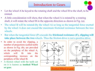
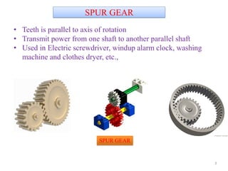
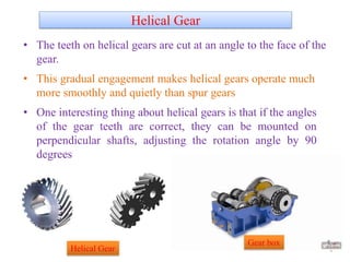
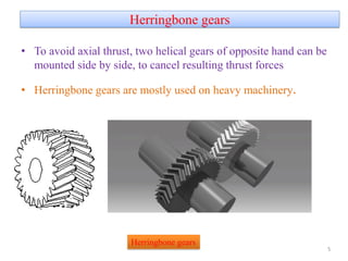
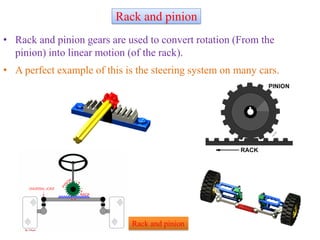
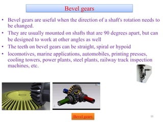
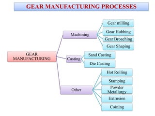
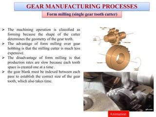
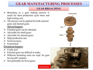
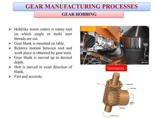
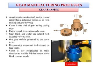
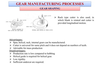
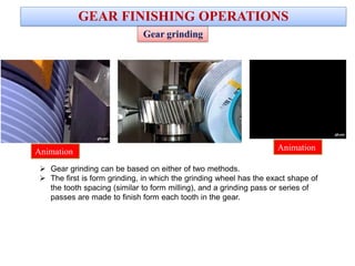
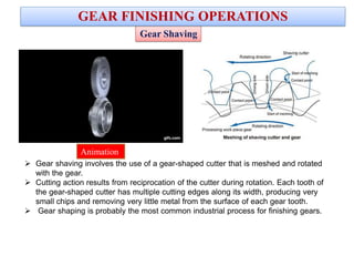
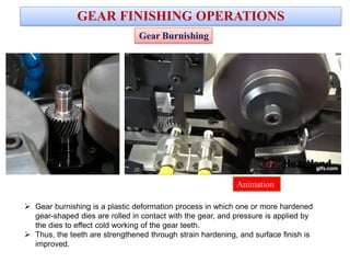
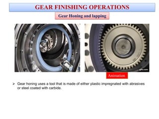
2. • Let the wheel A be keyed to the rotating shaft and the wheel B to the shaft, to be
rotated.
• A little consideration will show, that when the wheel A is rotated by a rotating
shaft, it will rotate the wheel B in the opposite direction as shown in Fig. (a).
• The wheel B will be rotated (by the wheel A) so long as the tangential force exerted
by the wheel A does not exceed the maximum frictional resistance between the two
wheels.
• But when the tangential force (P) exceeds the frictional resistance (F), slipping will
take place between the two wheels. Thus the friction drive is not a positive drive.
• In order to avoid the slipping, a
number of projections (called teeth)
as shown in Fig. (b), are provided
on the periphery of the wheel A,
which will fit into the
corresponding recesses on the
periphery of the wheel B.
• A friction wheel with the teeth cut
on it is known as toothed Wheel
or gear. 3
Introduction to Gears
Toothed Wheel or gear
3. SPUR GEAR
• Teeth is parallel to axis of rotation
• Transmit power from one shaft to another parallel shaft
• Used in Electric screwdriver, windup alarm clock, washing
machine and clothes dryer, etc.,
3
SPUR GEAR
4. Helical Gear
• The teeth on helical gears are cut at an angle to the face of the
gear.
• This gradual engagement makes helical gears operate much
more smoothly and quietly than spur gears
• One interesting thing about helical gears is that if the angles
of the gear teeth are correct, they can be mounted on
perpendicular shafts, adjusting the rotation angle by 90
degrees
4Helical Gear
Gear box
5. Herringbone gears
• To avoid axial thrust, two helical gears of opposite hand can be
mounted side by side, to cancel resulting thrust forces
• Herringbone gears are mostly used on heavy machinery.
5
Herringbone gears
6. • Rack and pinion gears are used to convert rotation (From the
pinion) into linear motion (of the rack).
• A perfect example of this is the steering system on many cars.
6
Rack and pinion
Rack and pinion
7. WORM GEAR
• Worm gears makes very large gear ratios possible.
WORM GEAR
8. Bevel gears
• Bevel gears are useful when the direction of a shaft's rotation needs to
be changed.
• They are usually mounted on shafts that are 90 degrees apart, but can
be designed to work at other angles as well
• The teeth on bevel gears can be straight, spiral or hypoid
• locomotives, marine applications, automobiles, printing presses,
cooling towers, power plants, steel plants, railway track inspection
machines, etc.
10Bevel gears
12. Form milling (single gear tooth cutter)
The machining operation is classified as
forming because the shape of the cutter
determines the geometry of the gear teeth.
The advantage of form milling over gear
hobbing is that the milling cutter is much less
expensive.
The disadvantage of form milling is that
production rates are slow because each tooth
space is created one at a time .
the gear blank must be indexed between each
pass to establish the correct size of the gear
tooth, which also takes time.
GEAR MANUFACTURING PROCESSES
Animation
13. GEAR MANUFACTURING PROCESSES
Broaching as a gear making process is
noted for short production cycle times and
high tooling cost.
The process can be applied for both external
gears and internal gears.
Advantages:
Finished gears can be obtained.
Advisable for small gears.
Advisable for internal gears.
High production rate.
Good accuracy.
Economical
Disadvantages:
Costly tool
External gears are difficult to make.
Different broaching tools are reqd. for gear
having diff. modules.
Not preferable for bevel gears.
GEAR BROACHING
Animation
14. GEAR MANUFACTURING PROCESSES
Hob(like worm cutter) is rotary tool
on which single or multi start
threads are cut.
Gear blank is mounted on table.
Relative motion between tool and
work piece is obtained by gear train.
Gear blank is moved up to desired
depth.
Hob is moved in axial direction of
blank.
Fast and accurate.
GEAR HOBBING
Animation
15. GEAR MANUFACTURING PROCESSES
GEAR SHAPING
A reciprocating cutting tool motion is used
rather than a rotational motion as in form
milling and gear hobbing.
Cutter is one kind of gear having cutting
edge.
Pinion or rack type cutter can be used.
Gear blank and cutter are rotated with
adjusted velocity ratio.
One gear tooth is generated by one cutter
tooth.
Reciprocating movement is dependent on
face width.
Cutter is also reciprocated in radial
direction to provide full depth mean while
blank remains steady.
Animation
16. GEAR MANUFACTURING PROCESSES
GEAR SHAPING
Rack type cutter is also used, in
which blank is rotated and cutter is
provided longitudinal motion.
Advantages:
Spur, helical, rack, internal gears can be manufactured.
Cutter is universal for same pitch and it does not depend on numbers of teeth.
Advisable for mass production
Disadvantages:
Production rate is low compared to hobbing
Helical guide is required for helical gear.
Low rigidity.
Sufficient undercut are required.
17. Gear grinding can be based on either of two methods.
The first is form grinding, in which the grinding wheel has the exact shape of
the tooth spacing (similar to form milling), and a grinding pass or series of
passes are made to finish form each tooth in the gear.
Gear grinding
GEAR FINISHING OPERATIONS
AnimationAnimation
18. Gear Shaving
Gear shaving involves the use of a gear-shaped cutter that is meshed and rotated
with the gear.
Cutting action results from reciprocation of the cutter during rotation. Each tooth of
the gear-shaped cutter has multiple cutting edges along its width, producing very
small chips and removing very little metal from the surface of each gear tooth.
Gear shaping is probably the most common industrial process for finishing gears.
GEAR FINISHING OPERATIONS
Animation
19. Gear burnishing is a plastic deformation process in which one or more hardened
gear-shaped dies are rolled in contact with the gear, and pressure is applied by
the dies to effect cold working of the gear teeth.
Thus, the teeth are strengthened through strain hardening, and surface finish is
improved.
Gear Burnishing
GEAR FINISHING OPERATIONS
Animation
20. Honing and lapping are two finishing processes that can be adapted to gear finishing using very
fine abrasives.
The tools in both processes usually possess the geometry of a gear that meshes with the gear to
be processed.
Gear lapping uses a cast iron tool (other metals are sometimes substituted), and the cutting action
is accomplished by the lapping compound containing abrasives.
Gear Honing and lapping
Gear Lapping
GEAR FINISHING OPERATIONS
Animation
21. Gear Honing and lapping
GEAR FINISHING OPERATIONS
Gear honing uses a tool that is made of either plastic impregnated with abrasives
or steel coated with carbide.
Animation