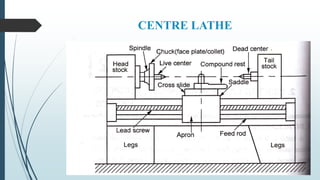
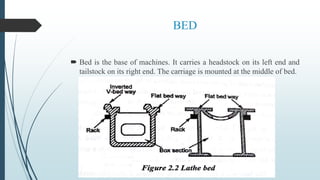
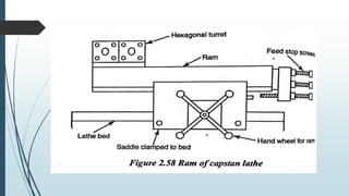
UNIT 2
TURNING MACHINES
Centre lathe, constructional features, specification, operations – taper
turning methods, thread cutting methods, special attachments,
machining time and power estimation. Capstan and turret lathes- tool
layout – automatic lathes: semi-automatic – single spindle: Swiss type,
automatic screw type – multi spindle:
CENTRE LATHE
The following are the principle parts of the
lathe
 Bed
 Head stock
 Tail stock
 Carriage
 Feed mechanism
BED
 Bed is the base of machines. It carries a headstock on its left end and
tailstock on its right end. The carriage is mounted at the middle of bed.
Head stock
 The headstock assembly is permanently fastened to the left end of the
bed. It carries a hollow spindle so that bars can be passed through it
when it is required.
 There are two types of headstock driving mechanisms as follows
 Back geared headstock
 All geared head stock
 Back gear arrangement is used for reducing the spindle speed which is
necessary for thread cutting and knurling.
Back geared headstock
All geared head stock
 All geared headstock is commonly used in modern lathes because of
the following advantages
 It gives wider range of spindle speeds.
 It is more efficient and compact.
 The vibration of spindle is reduced.
 Belt shifting is eliminated.
 More power can be transmitted.
Tail stock
 Tailstock is situated at the right end of the bed. It is used for supporting
the right end of the work piece.
Carriage
 The carriage is a moving part that slides over the guide ways between
headstock and tailstock. It carries the following parts.
 Saddle
 Cross slide
 Compound rest
 Tool post
Single screw tool post
Open side tool post
Four bolt tool post
Four way tool post
Feed mechanism
 Feed is defined as the movement of the tool relative to the work. There
are three types of feed longitudinal, cross and angular feed.
The following feed mechanisms are used
 Tumbler gear reversing mechanism
 Quick change gearbox
 Tumbler gear quick change gearbox
 Apron mechanism
Tumbler gear reversing mechanism
Quick change gearbox
Tumbler gear quick change gearbox
Apron mechanism
Specification of a lathe
Types of lathe
 Lathes are classified in many ways with respect to size, design, method of drive and purposes.
 Speed lathe
 Wood working lathe
 Metal spinning lathe
 Metal turning lathe
 Polishing lathe
 Engine lathe
 Step cone pulley drive lathe
 Geared lathe
 Variable speed lathe
 Bench lathe
 Tool room lathe
 Semi automatic lathe
 Capstan lathe
 Turret lathe
 Automatic lathe
 Special purpose lathe
 Copying lathe
Operations in lathe
TAPER TURNING METHODS
Form tool method
Tailstock set over method
Compound rest method
Taper turning attachment method
Form tool method
 It is one of the simplest methods to produce short taper.
 Taper length should be less than the tool cutting edge length.
Tailstock set over method
Compound rest method
Taper turning attachment method
THREAD CUTTING METHODS
 Thread cutting is done in different methods
Reversing the machine
Marketing the lathe parts
Using a chasing dial or thread indicator
Using thread chaser
Using a chasing dial or thread indicator
SPECIAL ATTACHMENTS
 Generally milling and grinding are performed on lathes by using special
attachments
Milling attachments
 Milling is the process of removing metal by moving the work against a
rotating cutter. this operation is carried out in two methods depending
upon the form of profiles.
For cutting grooves or keyways
For cutting multiple grooves and gear wheel
Grinding attachment
 Grinding is the operation of removing metal in fine form of chips. It is
done by moving the work against a rotating abrasive wheel. This
abrasive wheel is known as grinding wheel.
WORK HOLDING DEVICES
Some of the standard work holding devices used to hold
the work in a lathe are given below.
Chucks
Centres
Face plate
Angle plate
Mandrels
Steady and follower rest
Chucks
Three jaw chuck or self centering chuck
Four jaw chuck or independent chuck
Magnetic chuck
Three jaw chuck or self centering chuck
Four jaw chuck or independent chuck
Magnetic chuck
Centres
Face plate
Angle plate
Steady and follower rest
AUTOMATIC LATHES AND SEMI
AUTOMATIC LATHES
 In an ordinary centre lathe, changing and setting of tools consume
more time.
 It reduces the rate of production and increases the cost of production.
 The changes of centre lathe into some special lathes is called semi
automatic lathes and automatic lathes.
 The turret lathes are used in heavy jobs whereas the capstan lathe is
used for light and small jobs.
Capstan and Turret lathe
THE MAIN PARTS OF CAPSTAN AND
TURRET LATHES
 Bed
 Cross slide
 Head stock
 Turret head and saddle
BED
 Bed is the base part of the lathe.
 It is box type which is made of cast iron.
 The bed should be strong and rigid to withstand heavy loads, force
and vibrations during machining.
CROSS SLIDE
 The two types of cross slides are as follows
Reach over type
It is mounted on bed guide ways in between head stock and turret.
The cross slide has two tool posts. The tool post can move both in
perpendicular and parallel direction to the spindle axis. In the rear
tool post, the parting off tool is clamped in an inverted position to
make the direction of work piece anti clock wise with respect to
tool movement.
Side hung type
This type of cross slide is entirely supported on the front way
which has no rear tool post. It provides a greater swing capacity to
accommodate large diameter work piece. It is mainly used in turret
lathe.
HEAD STOCK
 Headstock of capstan and turret lathe is similar to a head in ordinary
centre lathes but heavier in construction.
 The four main types of head stock are as follows
 Step cone pulley driven head stock
 Direct electric motor driven head stock
 All geared head stock
 Pre-selective stock
SADDLE
 In a capstan lathe, the turret head is mounted on a ram which slides
on the saddle. It can be positioned on lathe bed ways and clamped
well.
 In a turret lathe, the turret head is mounted on the saddle itself which
slides on the bed ways during machining. It is mainly used in turret
lathes.
TURRET HEAD
 A turret head has a hexagonal block having six faces with a bore for
mounting six or more than six tools at a time.
 Turret head is mounted on the ram fitted with turret slides
longitudinally on a saddle.
 Each tool is indexed through 60° by the rotation of a circular plate. The
circular plate is automatically indexed along with the turret head.
Bringing the next tool into the cutting position is known as Geneva
mechanism.
GENEVA MECHANISM (OR) INDEXING
MECHANISM
 The turret is provided with automatic indexing mechanism. To index the
turret by 1/6 of a revolution, the ram is returned to the starting position.
Then, the next tool comes into position to perform the machining
operation.
WORKING PRINCIPLE OF CAPSTAN AND
TURRET LATHES
 Drilling, boring, reaming, counter boring, turning and threading tools are
mounted on the hexagonal turret head.
 Forming, chamfering, knurling and necking tools are mounted at the front
end of the square turret.
 Parting off tool is mounted on the rear end of the square turret in an
inverted or in a reversed position.
SPECIFICATION OF CAPSTAN AND
TURRET LATHES
 Number of spindle speeds
 Number of feeds for the carriage
 Number of feeds for the turret
 Net weight of the machine
 Floor space required
 Power of the motor required
ADVANTAGES OF CAPSTAN AND
TURRET LATHES
 The production rate is high
 Heavier and larger work piece chucking can be done
 It has wider range of speeds
 Larger number of tools can be held
 More than one operation can be performed at the same time
 It is more rigid. Hence, its withstands heavy cuts
 Semi skilled operators are enough
 Labour cost is less
Sl
No.
CAPSTAN LATHE TURRET LATHE
1 Turret head is mounted on a ram
which slides over the saddle
Turret head is directly mounted on saddle.
But it slides on the bed
2 The turret movement is limited The turret moves on the entire length of the
bed without any restrictions
3 Hence, shorter workpiece can be
machined
Longer workpiece can be machined
4 It does not provide rigidity It provide rigidity and strong
5 It is very much useful for light duty
application
It is useful for heavy duty application
6 Turret head moved manually Turret head cannot moved manually
7 The maximum size of 60 mm diameter
work can be accommodated
It can accommodate only 125 mm to 220mm
WORK HOLDING DEVICES
The work holding devices used on capstan and turret
lathes are mostly automatic types. It reduces the setting
time.
Collets
Draw back collet
Push out collet
Dead length collet
Chucks
Fixture
COLLETS
Draw back collet
Push out collet
Dead length collet
Chucks
Fixture
 A specially designed member to locate and grip a work piece is
called as fixture. It is mounted on the spindle by replacing a chuck
or collet.
BAR FEEDING MECHANISM
TOOL HOLDING DEVICES
 To hold these tools in the respective positions, the various types of tool holders are fitted in
a hexagonal turret or front tool post of the square turret or in the rear tool post.
 The following are the various types of tool holders
 Straight cutter tool holder
 Adjustable angle cutter tool holder
 Multiple cutter holder
 Offset cutter holder
 Sliding tool holder
 Knee tool holder
 Flange tool holder
 Roller steady box tool holder
 Self opening type die holder
 Knurling tool holder
 Collapsible taps
 Combination tool holder
Straight cutter tool holder
Adjustable angle cutter tool holder
Multiple cutter holder
Offset cutter holder
Sliding tool holder
Knee tool holder
Flange tool holder
Roller steady box tool holder
Combination tool holder
Self opening type die holder
Knurling tool holder
Collapsible taps
TOOL LAYOUTS
 Turret and capstan lathe are mainly used for machining workpieces
in rapid speed. Before starting the production, the following works
are carried out.
Selection of tools
Designing of special tools
Selection of speeds
Selection of feeds
Setting the required length of work piece.
Tool layouts mainly consist of three stages
 Planning and scheduling stage
 Detailed sketching of various stages
 Sketching the plan showing the various tools
AUTOMATIC LATHES
 In automatic lathes, all operations required to finish off the work piece are
automatically done without the attention of an operator.
 These machines are meant for producing identical parts without
participation of an operator.
 All operations including loading and unloading are automatically done. By
using the control system, all working and idle operations are performed in
a definite sequence.
ADVANTAGES OF AUTOMATIC LATHES
 Mass production of identical parts is highly achieved
 High accuracy is maintained
 Time of production is minimized
 Less floor space is required
 Unskilled labour is enough
 It minimizes the labour cost
 One operator can be utilized to operate more than one machine.
Classification of automatic lathes
 Classification according to the type of work material used
 Bar stock machine
 Chucking machine
 Classification according to the number of spindles
 Single spindle automats
 Multi spindle automats
 Classification according to the arrangements of spindles
 Horizontal spindle type
 Vertical spindle type
 Classification according to the feed control
 Single cam shaft rotating at constant speed
 Single cam shaft with two speeds
 Two cam shaft
 Classification according to the use
 Single purpose machine
 General purpose machine
SINGLE SPINDLE AUTOMATIC LATHES
The following types of single spindle
automatic lathe are mostly used
 Automatic cutting off machine
 Automatic screw cutting machine
 Swiss type automatic screw machine
Automatic cutting off machine
Automatic screw cutting machine
Swiss type automatic screw machine
It consists of four major parts
 The sliding headstock through which the bar stock is passed and gripped
by a carbide lined guide bush
 The camshaft which controls the bar stock and cutting tool movements
 The tool bracket which supports five tool slides and a bush for stock
 Auxiliary attachments for performing various operations such as knurling,
drilling, tapping, screwing, slotting, recessing etc.
Working principle
 The bar stock is held in the rotating spindle by a collet check. head stock
slides along the bed ways with the rotating bar stock. This headstock
movement gives a longitudinal feed to the work.
 All tools in the tool slides remove materials from the work piece at the
same time. The tool in the feed base attachment may also do operations
such as drilling.
Advantages of Swiss type screw machine
 It is used to manufacture precision turning of small parts
 It has five tool slides
 Wide range of speeds is available
 It is rigid in construction
 Tolerance of 0.005 to 0.0125mm is obtained
Multi spindle automatic lathes
 Multiple spindle automatic lathes are machines which can produce larger
work pieces than single spindle automats.
 The principle advantage of the multi spindle automat is that it has a tool
slide working simultaneously on the jobs on all spindles and hence, the
time for producing a piece is the time for the longest cut
Classification of multi spindle automatic lathes
 According to the type of work piece used
Bar type machine
Chucking type machine
 According to the arrangement of spindle
Horizontal spindle type
Vertical spindle type
 According to the principle of operation
Parallel action type
Progressive action type
Parallel action Multiple spindle automatic machine
Progressive action Multiple spindle automatic
machine
Sl
No.
Parallel action machine Progressive action machine
1 Same operation is done on all jobs in all
spindles
Different operations are done on jobs
at each station one after another
2 The rate of production is very high The rate of production is moderate
3 If anything goes wrong in one station,
the production in that particular station
only is affected
If anything goes wrong in one station,
the production is completely affected
in all station.
4 Small parts of simple shapes are
produced
Parts of complicated shapes can be
produced
Sl
No.
Single spindle Multi spindle
1 There is only one spindle There are 2,4,5,6 or 8 spindle
2 Only one work piece is machined at a
time
A number of work pieces are machined at
a time
3 The rate of production is low The rate of production is high
4 Machining accuracy is higher Machining accuracy is lower
5 Tool setting time and tooling cost is less Tool setting time and tooling cost is more

MANUFACTURING PROCESS-II

  • 1.
    UNIT 2 TURNING MACHINES Centrelathe, constructional features, specification, operations – taper turning methods, thread cutting methods, special attachments, machining time and power estimation. Capstan and turret lathes- tool layout – automatic lathes: semi-automatic – single spindle: Swiss type, automatic screw type – multi spindle:
  • 2.
  • 3.
    The following arethe principle parts of the lathe  Bed  Head stock  Tail stock  Carriage  Feed mechanism
  • 4.
    BED  Bed isthe base of machines. It carries a headstock on its left end and tailstock on its right end. The carriage is mounted at the middle of bed.
  • 5.
    Head stock  Theheadstock assembly is permanently fastened to the left end of the bed. It carries a hollow spindle so that bars can be passed through it when it is required.  There are two types of headstock driving mechanisms as follows  Back geared headstock  All geared head stock
  • 6.
     Back geararrangement is used for reducing the spindle speed which is necessary for thread cutting and knurling. Back geared headstock
  • 7.
    All geared headstock  All geared headstock is commonly used in modern lathes because of the following advantages  It gives wider range of spindle speeds.  It is more efficient and compact.  The vibration of spindle is reduced.  Belt shifting is eliminated.  More power can be transmitted.
  • 9.
    Tail stock  Tailstockis situated at the right end of the bed. It is used for supporting the right end of the work piece.
  • 10.
    Carriage  The carriageis a moving part that slides over the guide ways between headstock and tailstock. It carries the following parts.  Saddle  Cross slide  Compound rest  Tool post Single screw tool post Open side tool post Four bolt tool post Four way tool post
  • 12.
    Feed mechanism  Feedis defined as the movement of the tool relative to the work. There are three types of feed longitudinal, cross and angular feed.
  • 13.
    The following feedmechanisms are used  Tumbler gear reversing mechanism  Quick change gearbox  Tumbler gear quick change gearbox  Apron mechanism
  • 14.
  • 15.
  • 16.
    Tumbler gear quickchange gearbox
  • 17.
  • 18.
  • 19.
    Types of lathe Lathes are classified in many ways with respect to size, design, method of drive and purposes.  Speed lathe  Wood working lathe  Metal spinning lathe  Metal turning lathe  Polishing lathe  Engine lathe  Step cone pulley drive lathe  Geared lathe  Variable speed lathe  Bench lathe  Tool room lathe  Semi automatic lathe  Capstan lathe  Turret lathe  Automatic lathe  Special purpose lathe  Copying lathe
  • 20.
  • 21.
    TAPER TURNING METHODS Formtool method Tailstock set over method Compound rest method Taper turning attachment method
  • 22.
    Form tool method It is one of the simplest methods to produce short taper.  Taper length should be less than the tool cutting edge length.
  • 24.
  • 26.
  • 27.
  • 28.
    THREAD CUTTING METHODS Thread cutting is done in different methods Reversing the machine Marketing the lathe parts Using a chasing dial or thread indicator Using thread chaser
  • 29.
    Using a chasingdial or thread indicator
  • 30.
    SPECIAL ATTACHMENTS  Generallymilling and grinding are performed on lathes by using special attachments Milling attachments  Milling is the process of removing metal by moving the work against a rotating cutter. this operation is carried out in two methods depending upon the form of profiles. For cutting grooves or keyways For cutting multiple grooves and gear wheel
  • 31.
    Grinding attachment  Grindingis the operation of removing metal in fine form of chips. It is done by moving the work against a rotating abrasive wheel. This abrasive wheel is known as grinding wheel.
  • 32.
    WORK HOLDING DEVICES Someof the standard work holding devices used to hold the work in a lathe are given below. Chucks Centres Face plate Angle plate Mandrels Steady and follower rest
  • 33.
    Chucks Three jaw chuckor self centering chuck Four jaw chuck or independent chuck Magnetic chuck
  • 34.
    Three jaw chuckor self centering chuck
  • 35.
    Four jaw chuckor independent chuck
  • 36.
  • 37.
  • 38.
  • 39.
  • 41.
  • 42.
    AUTOMATIC LATHES ANDSEMI AUTOMATIC LATHES  In an ordinary centre lathe, changing and setting of tools consume more time.  It reduces the rate of production and increases the cost of production.  The changes of centre lathe into some special lathes is called semi automatic lathes and automatic lathes.  The turret lathes are used in heavy jobs whereas the capstan lathe is used for light and small jobs.
  • 43.
  • 44.
    THE MAIN PARTSOF CAPSTAN AND TURRET LATHES  Bed  Cross slide  Head stock  Turret head and saddle
  • 45.
    BED  Bed isthe base part of the lathe.  It is box type which is made of cast iron.  The bed should be strong and rigid to withstand heavy loads, force and vibrations during machining.
  • 46.
    CROSS SLIDE  Thetwo types of cross slides are as follows Reach over type It is mounted on bed guide ways in between head stock and turret. The cross slide has two tool posts. The tool post can move both in perpendicular and parallel direction to the spindle axis. In the rear tool post, the parting off tool is clamped in an inverted position to make the direction of work piece anti clock wise with respect to tool movement. Side hung type This type of cross slide is entirely supported on the front way which has no rear tool post. It provides a greater swing capacity to accommodate large diameter work piece. It is mainly used in turret lathe.
  • 47.
    HEAD STOCK  Headstockof capstan and turret lathe is similar to a head in ordinary centre lathes but heavier in construction.  The four main types of head stock are as follows  Step cone pulley driven head stock  Direct electric motor driven head stock  All geared head stock  Pre-selective stock
  • 48.
  • 50.
     In acapstan lathe, the turret head is mounted on a ram which slides on the saddle. It can be positioned on lathe bed ways and clamped well.  In a turret lathe, the turret head is mounted on the saddle itself which slides on the bed ways during machining. It is mainly used in turret lathes.
  • 51.
    TURRET HEAD  Aturret head has a hexagonal block having six faces with a bore for mounting six or more than six tools at a time.  Turret head is mounted on the ram fitted with turret slides longitudinally on a saddle.  Each tool is indexed through 60° by the rotation of a circular plate. The circular plate is automatically indexed along with the turret head. Bringing the next tool into the cutting position is known as Geneva mechanism.
  • 52.
    GENEVA MECHANISM (OR)INDEXING MECHANISM  The turret is provided with automatic indexing mechanism. To index the turret by 1/6 of a revolution, the ram is returned to the starting position. Then, the next tool comes into position to perform the machining operation.
  • 54.
    WORKING PRINCIPLE OFCAPSTAN AND TURRET LATHES  Drilling, boring, reaming, counter boring, turning and threading tools are mounted on the hexagonal turret head.  Forming, chamfering, knurling and necking tools are mounted at the front end of the square turret.  Parting off tool is mounted on the rear end of the square turret in an inverted or in a reversed position.
  • 55.
    SPECIFICATION OF CAPSTANAND TURRET LATHES  Number of spindle speeds  Number of feeds for the carriage  Number of feeds for the turret  Net weight of the machine  Floor space required  Power of the motor required
  • 56.
    ADVANTAGES OF CAPSTANAND TURRET LATHES  The production rate is high  Heavier and larger work piece chucking can be done  It has wider range of speeds  Larger number of tools can be held  More than one operation can be performed at the same time  It is more rigid. Hence, its withstands heavy cuts  Semi skilled operators are enough  Labour cost is less
  • 57.
    Sl No. CAPSTAN LATHE TURRETLATHE 1 Turret head is mounted on a ram which slides over the saddle Turret head is directly mounted on saddle. But it slides on the bed 2 The turret movement is limited The turret moves on the entire length of the bed without any restrictions 3 Hence, shorter workpiece can be machined Longer workpiece can be machined 4 It does not provide rigidity It provide rigidity and strong 5 It is very much useful for light duty application It is useful for heavy duty application 6 Turret head moved manually Turret head cannot moved manually 7 The maximum size of 60 mm diameter work can be accommodated It can accommodate only 125 mm to 220mm
  • 58.
    WORK HOLDING DEVICES Thework holding devices used on capstan and turret lathes are mostly automatic types. It reduces the setting time. Collets Draw back collet Push out collet Dead length collet Chucks Fixture
  • 59.
  • 60.
  • 61.
  • 62.
  • 63.
  • 64.
    Fixture  A speciallydesigned member to locate and grip a work piece is called as fixture. It is mounted on the spindle by replacing a chuck or collet.
  • 65.
  • 66.
    TOOL HOLDING DEVICES To hold these tools in the respective positions, the various types of tool holders are fitted in a hexagonal turret or front tool post of the square turret or in the rear tool post.  The following are the various types of tool holders  Straight cutter tool holder  Adjustable angle cutter tool holder  Multiple cutter holder  Offset cutter holder  Sliding tool holder  Knee tool holder  Flange tool holder  Roller steady box tool holder  Self opening type die holder  Knurling tool holder  Collapsible taps  Combination tool holder
  • 67.
  • 68.
  • 69.
  • 70.
  • 71.
  • 72.
  • 73.
  • 74.
    Roller steady boxtool holder
  • 75.
  • 76.
  • 77.
  • 78.
  • 79.
    TOOL LAYOUTS  Turretand capstan lathe are mainly used for machining workpieces in rapid speed. Before starting the production, the following works are carried out. Selection of tools Designing of special tools Selection of speeds Selection of feeds Setting the required length of work piece.
  • 80.
    Tool layouts mainlyconsist of three stages  Planning and scheduling stage  Detailed sketching of various stages  Sketching the plan showing the various tools
  • 81.
    AUTOMATIC LATHES  Inautomatic lathes, all operations required to finish off the work piece are automatically done without the attention of an operator.  These machines are meant for producing identical parts without participation of an operator.  All operations including loading and unloading are automatically done. By using the control system, all working and idle operations are performed in a definite sequence.
  • 82.
    ADVANTAGES OF AUTOMATICLATHES  Mass production of identical parts is highly achieved  High accuracy is maintained  Time of production is minimized  Less floor space is required  Unskilled labour is enough  It minimizes the labour cost  One operator can be utilized to operate more than one machine.
  • 83.
    Classification of automaticlathes  Classification according to the type of work material used  Bar stock machine  Chucking machine  Classification according to the number of spindles  Single spindle automats  Multi spindle automats  Classification according to the arrangements of spindles  Horizontal spindle type  Vertical spindle type  Classification according to the feed control  Single cam shaft rotating at constant speed  Single cam shaft with two speeds  Two cam shaft  Classification according to the use  Single purpose machine  General purpose machine
  • 84.
  • 85.
    The following typesof single spindle automatic lathe are mostly used  Automatic cutting off machine  Automatic screw cutting machine  Swiss type automatic screw machine
  • 86.
  • 88.
  • 90.
    Swiss type automaticscrew machine
  • 91.
    It consists offour major parts  The sliding headstock through which the bar stock is passed and gripped by a carbide lined guide bush  The camshaft which controls the bar stock and cutting tool movements  The tool bracket which supports five tool slides and a bush for stock  Auxiliary attachments for performing various operations such as knurling, drilling, tapping, screwing, slotting, recessing etc.
  • 92.
    Working principle  Thebar stock is held in the rotating spindle by a collet check. head stock slides along the bed ways with the rotating bar stock. This headstock movement gives a longitudinal feed to the work.  All tools in the tool slides remove materials from the work piece at the same time. The tool in the feed base attachment may also do operations such as drilling.
  • 93.
    Advantages of Swisstype screw machine  It is used to manufacture precision turning of small parts  It has five tool slides  Wide range of speeds is available  It is rigid in construction  Tolerance of 0.005 to 0.0125mm is obtained
  • 94.
    Multi spindle automaticlathes  Multiple spindle automatic lathes are machines which can produce larger work pieces than single spindle automats.  The principle advantage of the multi spindle automat is that it has a tool slide working simultaneously on the jobs on all spindles and hence, the time for producing a piece is the time for the longest cut
  • 96.
    Classification of multispindle automatic lathes  According to the type of work piece used Bar type machine Chucking type machine  According to the arrangement of spindle Horizontal spindle type Vertical spindle type  According to the principle of operation Parallel action type Progressive action type
  • 97.
    Parallel action Multiplespindle automatic machine
  • 98.
    Progressive action Multiplespindle automatic machine
  • 99.
    Sl No. Parallel action machineProgressive action machine 1 Same operation is done on all jobs in all spindles Different operations are done on jobs at each station one after another 2 The rate of production is very high The rate of production is moderate 3 If anything goes wrong in one station, the production in that particular station only is affected If anything goes wrong in one station, the production is completely affected in all station. 4 Small parts of simple shapes are produced Parts of complicated shapes can be produced
  • 100.
    Sl No. Single spindle Multispindle 1 There is only one spindle There are 2,4,5,6 or 8 spindle 2 Only one work piece is machined at a time A number of work pieces are machined at a time 3 The rate of production is low The rate of production is high 4 Machining accuracy is higher Machining accuracy is lower 5 Tool setting time and tooling cost is less Tool setting time and tooling cost is more