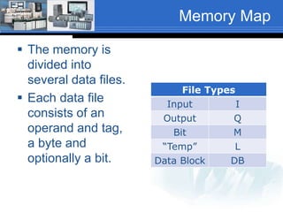
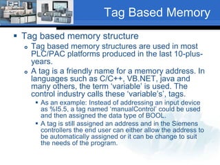
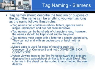
Supplement to Chapter 03 
Siemens – S7-1200 
Tags, Memory Structure and Addressing
Siemens Memory Structure 
 Load Memory 
 Memory area for the user 
program, data storage and 
configuration. This area is non-volatile 
storage. 
 Work Memory 
 Memory area that stores some 
elements of a user project that 
are needed while the user 
program is executing. This area 
is volatile. 
 Retentive Memory 
 Memory area that stores a limited 
quantity of work memory values. 
This area is non-volatile storage. 
Load 
Memory 
Work 
Memory 
Retentive 
Memory
Memory Map 
 The memory is 
divided into 
several data files. 
 Each data file 
consists of an 
operand and tag, 
a byte and 
optionally a bit. 
File Types 
Input I 
Output Q 
Bit M 
“Temp” L 
Data Block DB
Memory Map 
Memory Area Description 
I 
Process Image 
Input 
At the beginning of the scan cycle, the CPU records the status of the 
input field devices to ‘I’ memory . 
Q 
Process Image 
Output 
At the third step in the scan cycle, the CPU copies the state that the 
output field devices should be in to ‘Q’ memory. 
M 
Bit Memory 
A user program can read or write the data stored in the ‘M’ 
memory. Any code block can access ‘M’ memory. ‘M’ memory can be 
configured to retain the stored values after a power cycle. 
L 
“Temp” Memory 
The CPU allocates the temporary, or local memory whenever a code 
block is called to store data during the execution of the block. When 
block execution has completed, the CPU reallocates the local 
memory for the execution of other code blocks. 
DB 
Data Block 
The DB memory is used to store various types of data, including 
intermediate status of an operation or other information parameters 
for Function Blocks (FB) and data structures required for many 
instructions such as Timers and Counters. DB’s can be configured to 
be read only, write only or read/write. The data can be accessed by 
bit, bytes, words or double words.
Address Types 
 The processor can 
access address 
types as shown in 
the table. 
 Following is an 
example of an 
output address. 
Address Type 
Inputs (I) 
Outputs (Q) 
Bit Memory (M) 
Timers (DB) 
Counters (DB) 
Temporary (L) 
Data Block (DB) 
Peripheral Inputs (PI) 
Peripheral Outputs (PQ) 
Q1.2 
Output Byte 1 Bit 2 
Siemens uses Byte level addressing. More on this later.
Tag Based Memory 
 Tag based memory structure 
 Tag based memory structures are used in most 
PLC/PAC platforms produced in the last 10-plus-years. 
 A tag is a friendly name for a memory address. In 
languages such as C/C++, VB.NET, java and 
many others, the term ‘variable’ is used. The 
control industry calls these ‘variable’s’, tags. 
 As an example: Instead of addressing an input device 
as %I5.5, a tag named ‘manualControl’ could be used 
and then assigned the data type of BOOL. 
 A tag is still assigned an address and in the Siemens 
controllers the end user can either allow the address to 
be automatically assigned or it can be change to suit 
the needs of the program.
Tag Naming - Siemens 
 Tag names should describe the function or purpose of 
the tag. The name can be anything you want as long 
as the name follows these rules: 
 Tag names can contain numbers, letters, spaces and a 
single underscore and are not case sensitive. 
 Tag names can be hundreds of characters long; however, 
the names should be kept short and to the point. 
 Tag names must begin with a letter or a single underscore. 
They can not end with an underscore or begin with a 
number. 
 Mixed case is used for ease of reading such as: 
Conveyor_2 or Conveyor2 and not CONVEYOR_2 OR 
CONVEYOR2. 
 When viewing tags in the TIA-Portal software the tags are 
displayed in a spreadsheet similar to Microsoft Excel. The 
columns in the sheet can be sorted in any method the user 
desires.
Invalid Tag Names 
 The following tag names are invalid: 
 Conveyor2_motor_ 
 This tag is invalid because a tag name cannot end 
with an underscore. 
 2Conveyor_motor 
 This tag is invalid because a tag name cannot start 
with a number.
Viewing/Sorting Tags 
 When viewing tags in the TIA Portal software the tags 
can be displayed in alphabetical order. Use this to your 
advantage when naming tags. Using the same word to 
start tag names from the same process areas will keep 
them grouped together. As an example: 
 Conveyor2_endOfConveyor 
 Conveyor2_inputSensor 
 Conveyor2_motor 
Would keep all the tags associated with Conveyor2 
grouped together. 
 However, TIA Portal also allows the creation of more 
than one tag table. Therefore, tag tables can be 
created for the various sections and/or functions of a 
machine or process.
Tag Data Types 
 When a tag is created it must be assigned a 
data type. The data type is assigned based on 
the type of data that will be stored in the tag. 
 There are many different data types. The five 
basic data types are: 
 Bool (Bit) Bit level data (0 or 1) 
 Sint (Byte) 8-bit integer data (Single Integer) 
 Int 16-bit integer data 
 Dint 32-bit integer data (Double Integer) 
 Real 32-bit floating point data
Basic Data Types 
Data Type Bits 
31 16 15 8 7 1 0 
Bool (1-bit) Not used Not used Not used 0 or 1 
Sint (Byte) 
Not used Not used -128 to 127 
(8-bits) 
Int (16-bits) Not used -32,768 to 32,767 
Dint (32-bits) -2,147,483,648 to 2,147,483,647 
Real 
-3.40282347E38 to -1.17549435E-38 (negative values) 
0 
1.17549435E-38 to 3.40282347E38 (positive values)
Memory/Project 
Organization 
 Memory and projects are organized in 
code blocks: 
 Organizational Blocks (OB) 
 Functions (FC) 
 Function Blocks (FB) 
 Data Blocks (DB)
Organizational Block (OB) 
 Organizational Blocks define the structure of 
a program. There are several types of OB’s: 
 Program Cycle – Repeatedly executes while the 
processor is in Run Mode. OB1 is the default 
block. 
 Startup – Executes one time when the processor 
mode is changed from Stop to Run; OB100. 
 Time Delay – Executes at specific time intervals, 
specified after an event is configured by the start 
interrupt (SRT-DINT) instruction. (Will not be 
covered). 
 Cyclic Interrupt – Executes at user defined time 
intervals that interrupt cyclic program execution. 
(Will not be covered).
Function (FC) 
 Functions are code blocks that do not 
retain memory values after execution. 
 Any data stored in tags during execution 
will be lost when execution leaves the 
function.
Function Block (FB) 
 Function blocks are code blocks that retain 
memory values after execution. 
 Function blocks behave similar to 
subroutines and can be “called” whenever 
and where ever their functionality is 
required.
Project Structure 
 Siemens projects consist of: 
 OB – Organizational Block 
 FB – Function Block 
 FC – Functions 
 DB – Data Block
Siemens Portal Project 
Project and Processor 
Object Blocks (OB) 
Function (FC) 
Function Block (FB) 
Data Block (DB) 
PLC Tags
Intro Portal Step 7 Lab 
 The next lab can be an instructor led or a 
self-paced introduction to TIA Portal Step 7 
and will cover: 
 Starting a new project 
 Configuring the hardware 
 Configuring communications 
 Entering ladder logic 
 Creating tags, assigning addresses and data 
types 
 Downloading the project and running the 
program.

07 chapter03 05_siemens_tags_memory_structure_fa14

  • 1.
    Supplement to Chapter03 Siemens – S7-1200 Tags, Memory Structure and Addressing
  • 2.
    Siemens Memory Structure  Load Memory  Memory area for the user program, data storage and configuration. This area is non-volatile storage.  Work Memory  Memory area that stores some elements of a user project that are needed while the user program is executing. This area is volatile.  Retentive Memory  Memory area that stores a limited quantity of work memory values. This area is non-volatile storage. Load Memory Work Memory Retentive Memory
  • 3.
    Memory Map The memory is divided into several data files.  Each data file consists of an operand and tag, a byte and optionally a bit. File Types Input I Output Q Bit M “Temp” L Data Block DB
  • 4.
    Memory Map MemoryArea Description I Process Image Input At the beginning of the scan cycle, the CPU records the status of the input field devices to ‘I’ memory . Q Process Image Output At the third step in the scan cycle, the CPU copies the state that the output field devices should be in to ‘Q’ memory. M Bit Memory A user program can read or write the data stored in the ‘M’ memory. Any code block can access ‘M’ memory. ‘M’ memory can be configured to retain the stored values after a power cycle. L “Temp” Memory The CPU allocates the temporary, or local memory whenever a code block is called to store data during the execution of the block. When block execution has completed, the CPU reallocates the local memory for the execution of other code blocks. DB Data Block The DB memory is used to store various types of data, including intermediate status of an operation or other information parameters for Function Blocks (FB) and data structures required for many instructions such as Timers and Counters. DB’s can be configured to be read only, write only or read/write. The data can be accessed by bit, bytes, words or double words.
  • 5.
    Address Types The processor can access address types as shown in the table.  Following is an example of an output address. Address Type Inputs (I) Outputs (Q) Bit Memory (M) Timers (DB) Counters (DB) Temporary (L) Data Block (DB) Peripheral Inputs (PI) Peripheral Outputs (PQ) Q1.2 Output Byte 1 Bit 2 Siemens uses Byte level addressing. More on this later.
  • 6.
    Tag Based Memory  Tag based memory structure  Tag based memory structures are used in most PLC/PAC platforms produced in the last 10-plus-years.  A tag is a friendly name for a memory address. In languages such as C/C++, VB.NET, java and many others, the term ‘variable’ is used. The control industry calls these ‘variable’s’, tags.  As an example: Instead of addressing an input device as %I5.5, a tag named ‘manualControl’ could be used and then assigned the data type of BOOL.  A tag is still assigned an address and in the Siemens controllers the end user can either allow the address to be automatically assigned or it can be change to suit the needs of the program.
  • 7.
    Tag Naming -Siemens  Tag names should describe the function or purpose of the tag. The name can be anything you want as long as the name follows these rules:  Tag names can contain numbers, letters, spaces and a single underscore and are not case sensitive.  Tag names can be hundreds of characters long; however, the names should be kept short and to the point.  Tag names must begin with a letter or a single underscore. They can not end with an underscore or begin with a number.  Mixed case is used for ease of reading such as: Conveyor_2 or Conveyor2 and not CONVEYOR_2 OR CONVEYOR2.  When viewing tags in the TIA-Portal software the tags are displayed in a spreadsheet similar to Microsoft Excel. The columns in the sheet can be sorted in any method the user desires.
  • 8.
    Invalid Tag Names  The following tag names are invalid:  Conveyor2_motor_  This tag is invalid because a tag name cannot end with an underscore.  2Conveyor_motor  This tag is invalid because a tag name cannot start with a number.
  • 9.
    Viewing/Sorting Tags When viewing tags in the TIA Portal software the tags can be displayed in alphabetical order. Use this to your advantage when naming tags. Using the same word to start tag names from the same process areas will keep them grouped together. As an example:  Conveyor2_endOfConveyor  Conveyor2_inputSensor  Conveyor2_motor Would keep all the tags associated with Conveyor2 grouped together.  However, TIA Portal also allows the creation of more than one tag table. Therefore, tag tables can be created for the various sections and/or functions of a machine or process.
  • 10.
    Tag Data Types  When a tag is created it must be assigned a data type. The data type is assigned based on the type of data that will be stored in the tag.  There are many different data types. The five basic data types are:  Bool (Bit) Bit level data (0 or 1)  Sint (Byte) 8-bit integer data (Single Integer)  Int 16-bit integer data  Dint 32-bit integer data (Double Integer)  Real 32-bit floating point data
  • 11.
    Basic Data Types Data Type Bits 31 16 15 8 7 1 0 Bool (1-bit) Not used Not used Not used 0 or 1 Sint (Byte) Not used Not used -128 to 127 (8-bits) Int (16-bits) Not used -32,768 to 32,767 Dint (32-bits) -2,147,483,648 to 2,147,483,647 Real -3.40282347E38 to -1.17549435E-38 (negative values) 0 1.17549435E-38 to 3.40282347E38 (positive values)
  • 12.
    Memory/Project Organization Memory and projects are organized in code blocks:  Organizational Blocks (OB)  Functions (FC)  Function Blocks (FB)  Data Blocks (DB)
  • 13.
    Organizational Block (OB)  Organizational Blocks define the structure of a program. There are several types of OB’s:  Program Cycle – Repeatedly executes while the processor is in Run Mode. OB1 is the default block.  Startup – Executes one time when the processor mode is changed from Stop to Run; OB100.  Time Delay – Executes at specific time intervals, specified after an event is configured by the start interrupt (SRT-DINT) instruction. (Will not be covered).  Cyclic Interrupt – Executes at user defined time intervals that interrupt cyclic program execution. (Will not be covered).
  • 14.
    Function (FC) Functions are code blocks that do not retain memory values after execution.  Any data stored in tags during execution will be lost when execution leaves the function.
  • 15.
    Function Block (FB)  Function blocks are code blocks that retain memory values after execution.  Function blocks behave similar to subroutines and can be “called” whenever and where ever their functionality is required.
  • 16.
    Project Structure Siemens projects consist of:  OB – Organizational Block  FB – Function Block  FC – Functions  DB – Data Block
  • 17.
    Siemens Portal Project Project and Processor Object Blocks (OB) Function (FC) Function Block (FB) Data Block (DB) PLC Tags
  • 18.
    Intro Portal Step7 Lab  The next lab can be an instructor led or a self-paced introduction to TIA Portal Step 7 and will cover:  Starting a new project  Configuring the hardware  Configuring communications  Entering ladder logic  Creating tags, assigning addresses and data types  Downloading the project and running the program.