The document provides a comprehensive overview of computer architecture, detailing various types of computers such as personal computers, workstations, and supercomputers, along with core functional components including input, output, memory units, and the control unit. It outlines basic operational concepts like instruction execution, memory addressing, and various addressing modes, as well as performance measurements and instruction sequencing. Additionally, it covers the role of registers, arithmetic logic units, and the significance of clock cycles in overall processor performance.


![Register Transfer Notation:
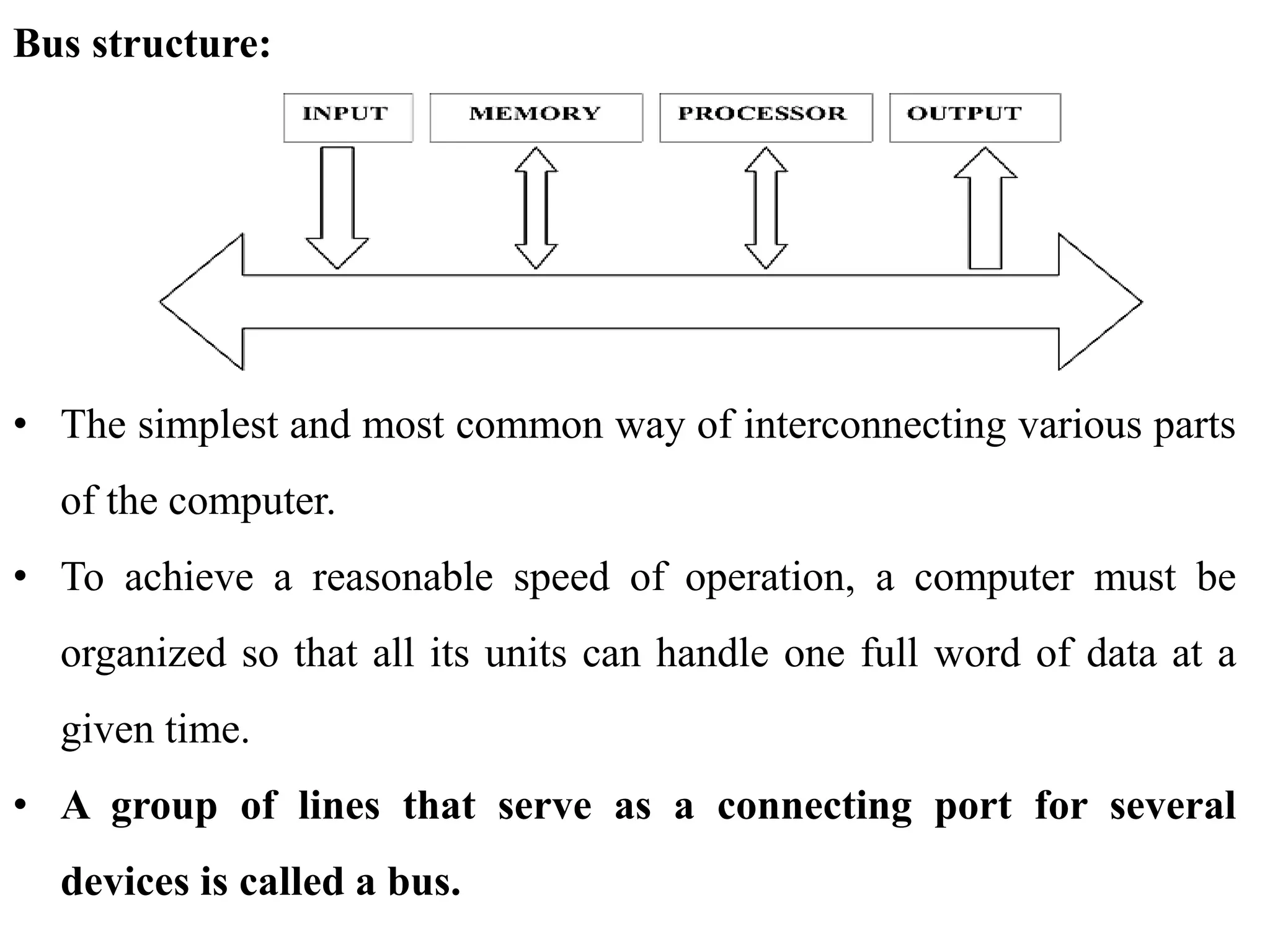
• Transfer of information from one location in the computer to another.
• Most of the time, we identify a location by a symbolic name standing
for its hardware binary address.
• LOC, PLACE, A, VAR2; processor registers names may be R0, R5;
and I/O register names may be DATAIN, OUTSTATUS, and so on.
R1← [LOC]
• Means that the contents of memory location LOC are transferred into
processor register R1.
R3← [R1] + [R2]
• operation that adds the contents of registers R1 and R2, and then
places their sum into register R3.](https://image.slidesharecdn.com/module3-240201094139-5a38e99d/75/Basic-Structure-of-Computers-Functional-Units-Basic-Operational-Concepts-Bus-structure-Performance-Processor-Clock-Basic-Performance-Equation-Clock-Rate-Performance-Measurement-pptx-24-2048.jpg)
![Basic Instructions:
• The operation of adding two numbers is a fundamental capability in
any computer. The statement
C=A+B
• In a high-level language program is a command to the computer to
add the current values of the two variables called A and B, and to
assign the sum to a third variable, C.
C← [A] + [B]
• assume that this instruction contains the memory addresses of the
three operands – A, B, and C. This three-address instruction can be
represented symbolically as
Add A, B, C](https://image.slidesharecdn.com/module3-240201094139-5a38e99d/75/Basic-Structure-of-Computers-Functional-Units-Basic-Operational-Concepts-Bus-structure-Performance-Processor-Clock-Basic-Performance-Equation-Clock-Rate-Performance-Measurement-pptx-26-2048.jpg)
![• Operands A and B are called the source operands, C is called the
destination operand, and Add is the operation to be performed on the
operands. A general instruction of this type has the format.
Operation Source1, Source 2, Destination
• Suppose that two- address instructions of the form
Operation Source, Destination
• Are available. An Add instruction of this type is
Add A, B
• Which performs the operation?
B← [A] + [B]](https://image.slidesharecdn.com/module3-240201094139-5a38e99d/75/Basic-Structure-of-Computers-Functional-Units-Basic-Operational-Concepts-Bus-structure-Performance-Processor-Clock-Basic-Performance-Equation-Clock-Rate-Performance-Measurement-pptx-27-2048.jpg)
![• The problem can be solved by using another two-address instruction
that copies the contents of one memory location into another. Such an
instruction is
Move B, C
• Using only one-address instructions, the operation C← [A] + [B] can
be performed by executing the sequence of instructions
Load A
Add B
Store C
• Let Ri represent a general-purpose register. The instructions
Load A, Ri
Store Ri, A and
Add A, Ri](https://image.slidesharecdn.com/module3-240201094139-5a38e99d/75/Basic-Structure-of-Computers-Functional-Units-Basic-Operational-Concepts-Bus-structure-Performance-Processor-Clock-Basic-Performance-Equation-Clock-Rate-Performance-Measurement-pptx-28-2048.jpg)
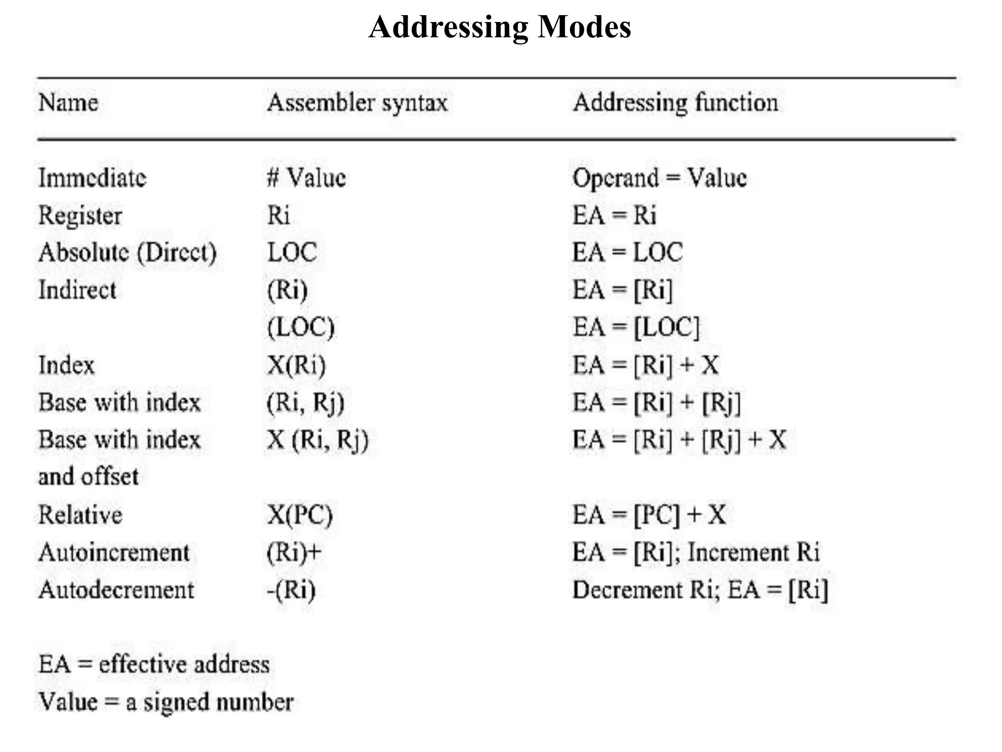
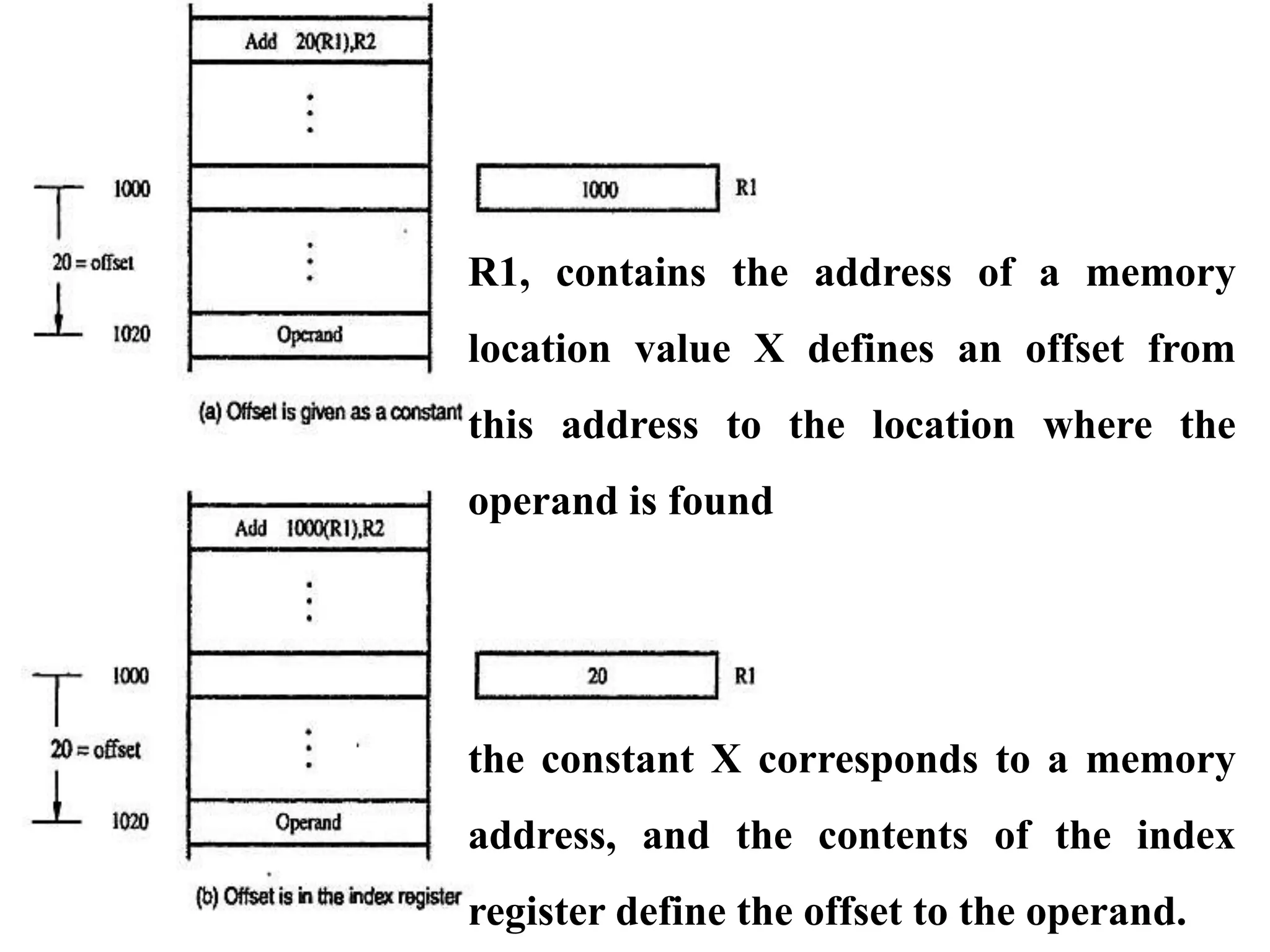
![Indexing and Arrays:
• Index mode: the effective address of the operand is generated by
adding a constant value to the contents of a register.
X (Ri)
Where X denotes the constant value contained in the instruction and Ri is
the name of the register involved. The effective address of the operand is
given by
EA = X + [Rj]
The contents of the index register are not changed in the process
of generating the effective address. In an assembly language program,
the constant X may be given either as an explicit number or as a
symbolic name](https://image.slidesharecdn.com/module3-240201094139-5a38e99d/75/Basic-Structure-of-Computers-Functional-Units-Basic-Operational-Concepts-Bus-structure-Performance-Processor-Clock-Basic-Performance-Equation-Clock-Rate-Performance-Measurement-pptx-38-2048.jpg)