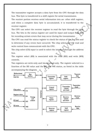
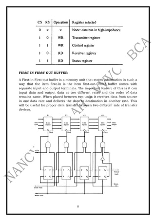
1
ASYNCHRONOUS DATA TRANSFER
Synchronous and Asynchronous Operations
1. Synchronous Operations:- All devices derive the timing information
from clock line.
2. Asynchronous Operations:- No common clock
Asynchronous data transfer:-
Asynchronous data transfer between two independent units requires that
control signals be transmitted between the communicating units to indicate
the time at which data is being transmitted.
Two Asynchronous Data Transfer methods:-
Strobe Pulse:- It is supplied by one unit to indicate the other unit when the
transfer has to occur.
Handshaking:- A control signal is accompanied with each data being
transmitted to indicate the presence of data. The receiving unit responds
with another control signal to acknowledge receipt of data.
The strobe pulse method and the handshaking method of asynchronous
data transfer are not restricted to I/O transfers. In fact, they are used
extensively on numerous occasions requiring the transfer of data between
two independent units. In the general case we consider the transmitting unit
as the source and the receiving unit as the destination.
For example, the CPU is the source unit during an output or a write
transfer and it is the destination unit during an input or a read transfer.
Strobe Control
This method of asynchronous data transfer uses a single control line to time
each transfer. The strobe may be activated by the source or the destination
unit.
i) Source Initiated Data Transfer:
The data bus carries the information from source to destination. The strobe
is a single line. The signal on this line informs the destination unit when a
data word is available in the bus.
The strobe signal is given after a brief delay, after placing the data on the
data bus. A brief period after the strobe pulse is disabled the source stops
sending the data.
2
Source-initiated strobe for data transfer
(ii) Destination Initiated Data Transfer:
In this case the destination unit activates the strobe pulse informing the
source to send data. The source places the data on the data bus. The
transmission is stopped briefly after the strobe pulse is removed.
The disadvantage of the strobe is that the source unit that initiates the
transfer has no way of knowing whether the destination unit has received
the data or not. Similarly if the destination initiates the transfer it has no
way of knowing whether the source unit has placed data on the bus or not.
This difficulty is solved by using hand shaking method of data transfer.
Destination-initiated strobe for data transfer
3
HANDSHAKING
In Strobe Methods
Source-Initiated
The source unit that initiates the transfer has no way of knowing
whether the destination unit has actually received data.
Destination-Initiated
The destination unit that initiates the transfer no way of knowing
whether the source has actually placed the data on the bus.
To solve this problem, the HANDSHAKE method introduces a second control
signal to provide a Reply to the unit that initiates the transfer.
SOURCE-INITIATED TRANSFER USING HANDSHAKE
4
Source-initiated transfer using Handshaking
 Allows arbitrary delays from one state to the next
 Permits each unit to respond at its own data transfer rate
 The rate of transfer is determined by the slower unit
DESTINATION-INITIATED TRANSFER USING HANDSHAKE
5
Destination-initiated Transfer using Handshaking
Handshaking provides a high degree of flexibility and reliability because the
successful completion of a data transfer relies on active participation by
both units.
If one unit is faulty, data transfer will not be completed and can be detected
by means of a timeout mechanism
ASYNCHRNOUS SERIAL TRANSFER
Data transfer between two units can be parallel or serial. In parallel data
transmission, each bit has its own path and the total message is
transmitted at the same time. In serial data transmission, each bit is sent in
sequence one at a time.
Parallel transmission is faster but requires many wires. So we use it for
short distances and where speed is important. Serial transmission is slower
but is less expensive.
Serial transmission can be synchronous or asynchronous. In synchronous
transmission, the two units share a common clock frequency and bits are
transmitted continuously at the rate dictated by the clock pulses.
In long distant serial transmission, each unit is driven by a separate clock of
the same frequency.
Synchronization signals are transmitted periodically between the two units
to keep their clocks in step with each other. In asynchronous transmission,
binary information is sent only when it is available and the line remains idle
when there is no information to be transmitted.
6
This is in contrast to synchronous transmission, where bits must be
transmitted continuously to keep the clock frequency in both units
synchronized with each other.
A serial asynchronous data transmission technique used in many
interactive terminals employs special bits that are inserted at both ends of
the character code.
With this technique, each character consists of three parts: a start bit, the
character bits, and stop bits. The convention is that the transmitter rests
at the 1-state when no characters are transmitted. The first bit, called the
start bit, is always a 0 and is used to indicate the beginning of a character.
The last bit called the stop bit is always a 1.
Receiver can detect a transmitted character from knowledge of the
transmission rules:
1. When a character is not being sent, the line is in the state 1.
2. The initiation of a character transmission is detected from the start
bit, which is always 0.
3. The character bits always follow the start bit.
4. After the last bit of the character is transmitted, a stop bit is detected
when the line returns to the I-state for at least one bit time.
ASYNCHRONOUS COMMUNICATION INTERFACE
It acts as both a transmitter and a receiver.
The interface is initialized for a particular mode of transfer by means of a
control byte that is loaded into its control register.
7
The transmitter register accepts a data byte from the CPU through the data
bus. This byte is transferred to a shift register for serial transmission.
The receiver portion receives serial information into an- other shift register,
and when a complete data byte is accumulated, it is transferred to the
receiver register.
The CPU can select the receiver register to read the byte through the data
bus. The bits in the status register are used for input and output flags and
for recording certain errors that may occur during the transmission.
The CPU can read the status register to check the status of the flag bits and
to determine if any errors have occurred. The chip select and the read and
write control lines communicate with the CPU.
The chip select (CS) input is used to select the interface through the address
bus.
The register select (RS) is associated with the read (RD) and write (WR)
controls.
Two registers are write-only and two are read-only. The register selected is a
function of the RS value and the RD and WR status, as listed in the table
accompanying the diagram.
8
FIRST IN FIRST OUT BUFFER
A First-in First-out buffer is a memory unit that stores information in such a
way that the item first-in is the item first-out. FIFO buffer comes with
separate input and output terminals. The important feature of this is it can
input data and output data at two different rates and the order of data
remains same. When placed between two units it receives data from source
in one data rate and delivers the data to destination in another rate. This
will be useful for proper data transfer between two different rate of transfer
devices.
9
When flip-flop Fi is set to 1, a 4-bit data will be stored in the corresponding
Register RI. A 0 in the flip-flop Fi indeicates there is no valid data in the
corresponding Register. Whenever the Fi bit of the control register is set and
Fi+1 bit is reset, a clock is generated causing register R(I+1) to accept the
data from the register RI. The same transition makes Fi to reset and Fi+1 to
set. Then the same process is repeated to the next stage and this ripple-
through operation makes the data to move on to the last stage. After that
the overall master clear is used to initialize all control register flip-flops to 0.

Asynchronous data transfer

  • 1.
    1 ASYNCHRONOUS DATA TRANSFER Synchronousand Asynchronous Operations 1. Synchronous Operations:- All devices derive the timing information from clock line. 2. Asynchronous Operations:- No common clock Asynchronous data transfer:- Asynchronous data transfer between two independent units requires that control signals be transmitted between the communicating units to indicate the time at which data is being transmitted. Two Asynchronous Data Transfer methods:- Strobe Pulse:- It is supplied by one unit to indicate the other unit when the transfer has to occur. Handshaking:- A control signal is accompanied with each data being transmitted to indicate the presence of data. The receiving unit responds with another control signal to acknowledge receipt of data. The strobe pulse method and the handshaking method of asynchronous data transfer are not restricted to I/O transfers. In fact, they are used extensively on numerous occasions requiring the transfer of data between two independent units. In the general case we consider the transmitting unit as the source and the receiving unit as the destination. For example, the CPU is the source unit during an output or a write transfer and it is the destination unit during an input or a read transfer. Strobe Control This method of asynchronous data transfer uses a single control line to time each transfer. The strobe may be activated by the source or the destination unit. i) Source Initiated Data Transfer: The data bus carries the information from source to destination. The strobe is a single line. The signal on this line informs the destination unit when a data word is available in the bus. The strobe signal is given after a brief delay, after placing the data on the data bus. A brief period after the strobe pulse is disabled the source stops sending the data.
  • 2.
    2 Source-initiated strobe fordata transfer (ii) Destination Initiated Data Transfer: In this case the destination unit activates the strobe pulse informing the source to send data. The source places the data on the data bus. The transmission is stopped briefly after the strobe pulse is removed. The disadvantage of the strobe is that the source unit that initiates the transfer has no way of knowing whether the destination unit has received the data or not. Similarly if the destination initiates the transfer it has no way of knowing whether the source unit has placed data on the bus or not. This difficulty is solved by using hand shaking method of data transfer. Destination-initiated strobe for data transfer
  • 3.
    3 HANDSHAKING In Strobe Methods Source-Initiated Thesource unit that initiates the transfer has no way of knowing whether the destination unit has actually received data. Destination-Initiated The destination unit that initiates the transfer no way of knowing whether the source has actually placed the data on the bus. To solve this problem, the HANDSHAKE method introduces a second control signal to provide a Reply to the unit that initiates the transfer. SOURCE-INITIATED TRANSFER USING HANDSHAKE
  • 4.
    4 Source-initiated transfer usingHandshaking  Allows arbitrary delays from one state to the next  Permits each unit to respond at its own data transfer rate  The rate of transfer is determined by the slower unit DESTINATION-INITIATED TRANSFER USING HANDSHAKE
  • 5.
    5 Destination-initiated Transfer usingHandshaking Handshaking provides a high degree of flexibility and reliability because the successful completion of a data transfer relies on active participation by both units. If one unit is faulty, data transfer will not be completed and can be detected by means of a timeout mechanism ASYNCHRNOUS SERIAL TRANSFER Data transfer between two units can be parallel or serial. In parallel data transmission, each bit has its own path and the total message is transmitted at the same time. In serial data transmission, each bit is sent in sequence one at a time. Parallel transmission is faster but requires many wires. So we use it for short distances and where speed is important. Serial transmission is slower but is less expensive. Serial transmission can be synchronous or asynchronous. In synchronous transmission, the two units share a common clock frequency and bits are transmitted continuously at the rate dictated by the clock pulses. In long distant serial transmission, each unit is driven by a separate clock of the same frequency. Synchronization signals are transmitted periodically between the two units to keep their clocks in step with each other. In asynchronous transmission, binary information is sent only when it is available and the line remains idle when there is no information to be transmitted.
  • 6.
    6 This is incontrast to synchronous transmission, where bits must be transmitted continuously to keep the clock frequency in both units synchronized with each other. A serial asynchronous data transmission technique used in many interactive terminals employs special bits that are inserted at both ends of the character code. With this technique, each character consists of three parts: a start bit, the character bits, and stop bits. The convention is that the transmitter rests at the 1-state when no characters are transmitted. The first bit, called the start bit, is always a 0 and is used to indicate the beginning of a character. The last bit called the stop bit is always a 1. Receiver can detect a transmitted character from knowledge of the transmission rules: 1. When a character is not being sent, the line is in the state 1. 2. The initiation of a character transmission is detected from the start bit, which is always 0. 3. The character bits always follow the start bit. 4. After the last bit of the character is transmitted, a stop bit is detected when the line returns to the I-state for at least one bit time. ASYNCHRONOUS COMMUNICATION INTERFACE It acts as both a transmitter and a receiver. The interface is initialized for a particular mode of transfer by means of a control byte that is loaded into its control register.
  • 7.
    7 The transmitter registeraccepts a data byte from the CPU through the data bus. This byte is transferred to a shift register for serial transmission. The receiver portion receives serial information into an- other shift register, and when a complete data byte is accumulated, it is transferred to the receiver register. The CPU can select the receiver register to read the byte through the data bus. The bits in the status register are used for input and output flags and for recording certain errors that may occur during the transmission. The CPU can read the status register to check the status of the flag bits and to determine if any errors have occurred. The chip select and the read and write control lines communicate with the CPU. The chip select (CS) input is used to select the interface through the address bus. The register select (RS) is associated with the read (RD) and write (WR) controls. Two registers are write-only and two are read-only. The register selected is a function of the RS value and the RD and WR status, as listed in the table accompanying the diagram.
  • 8.
    8 FIRST IN FIRSTOUT BUFFER A First-in First-out buffer is a memory unit that stores information in such a way that the item first-in is the item first-out. FIFO buffer comes with separate input and output terminals. The important feature of this is it can input data and output data at two different rates and the order of data remains same. When placed between two units it receives data from source in one data rate and delivers the data to destination in another rate. This will be useful for proper data transfer between two different rate of transfer devices.
  • 9.
    9 When flip-flop Fiis set to 1, a 4-bit data will be stored in the corresponding Register RI. A 0 in the flip-flop Fi indeicates there is no valid data in the corresponding Register. Whenever the Fi bit of the control register is set and Fi+1 bit is reset, a clock is generated causing register R(I+1) to accept the data from the register RI. The same transition makes Fi to reset and Fi+1 to set. Then the same process is repeated to the next stage and this ripple- through operation makes the data to move on to the last stage. After that the overall master clear is used to initialize all control register flip-flops to 0.