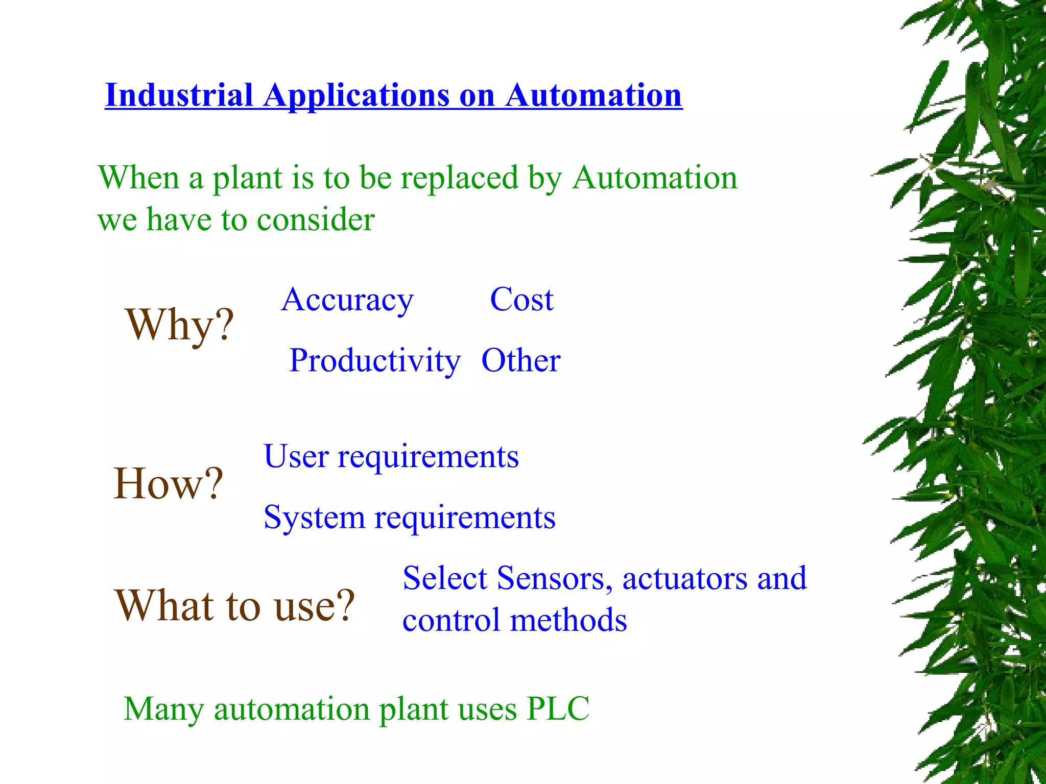
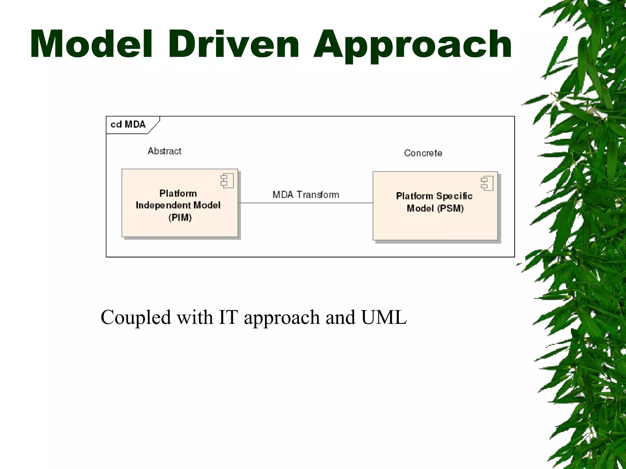
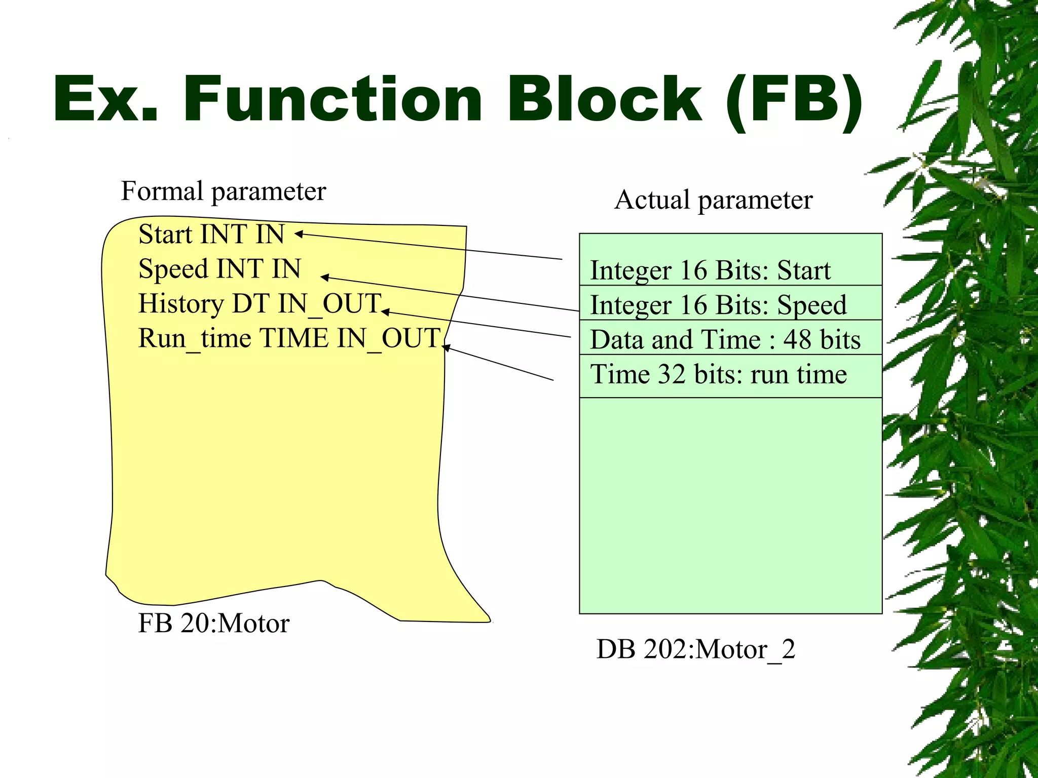
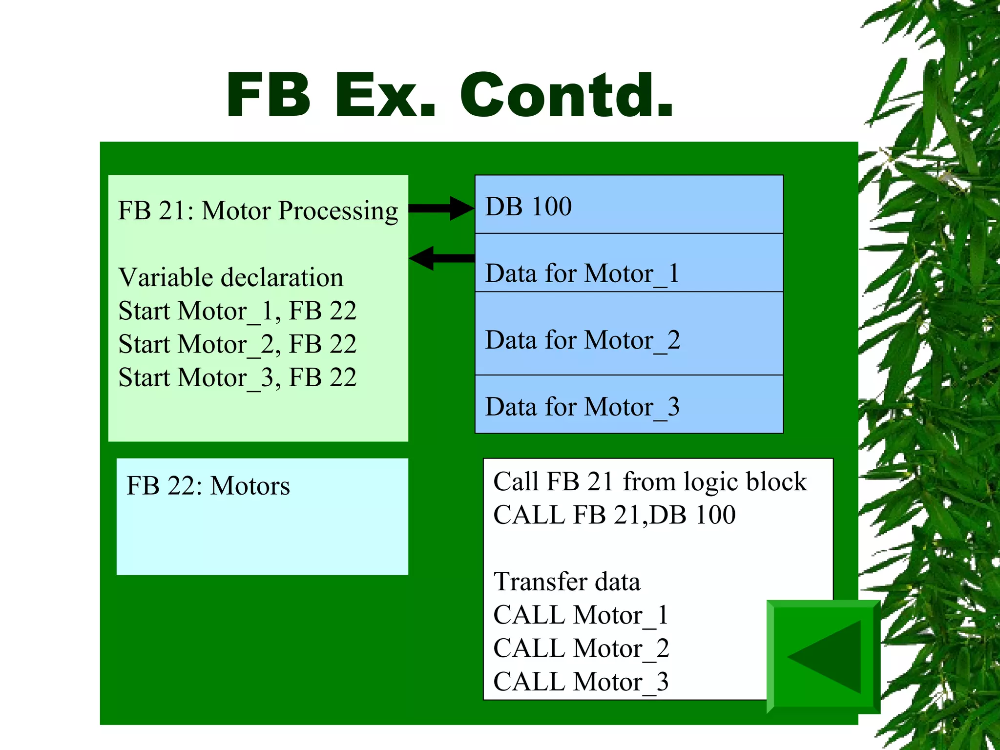
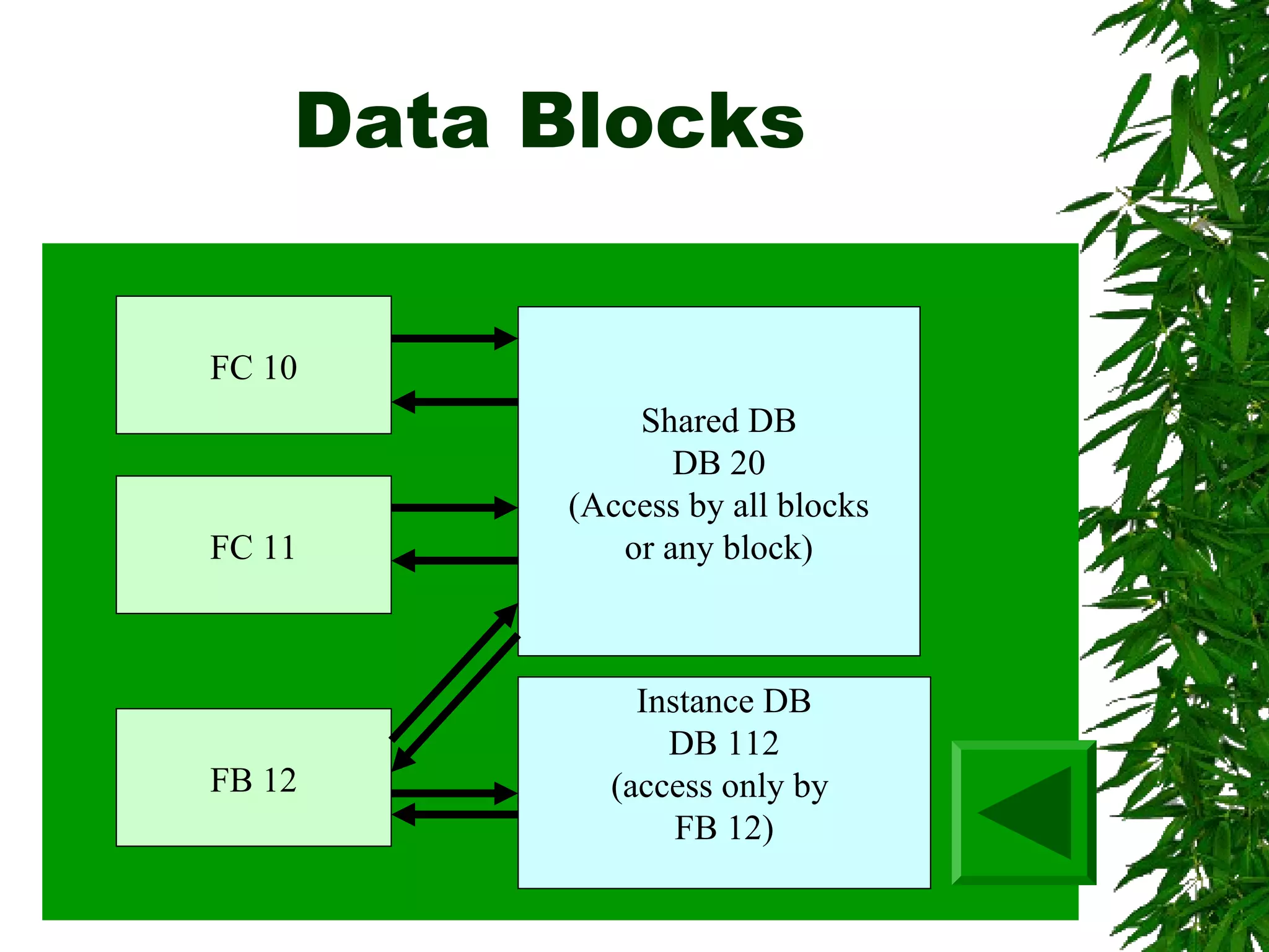
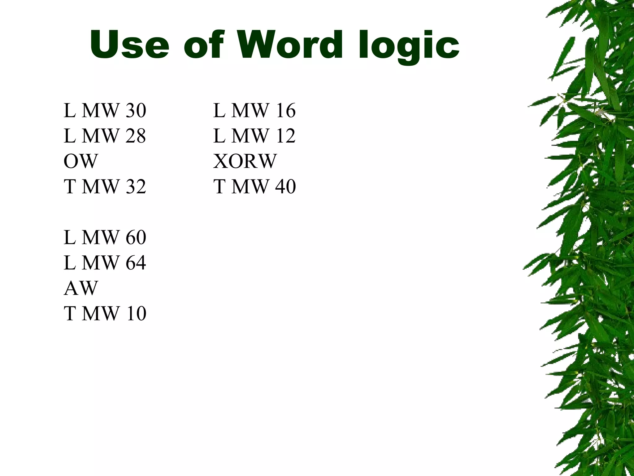
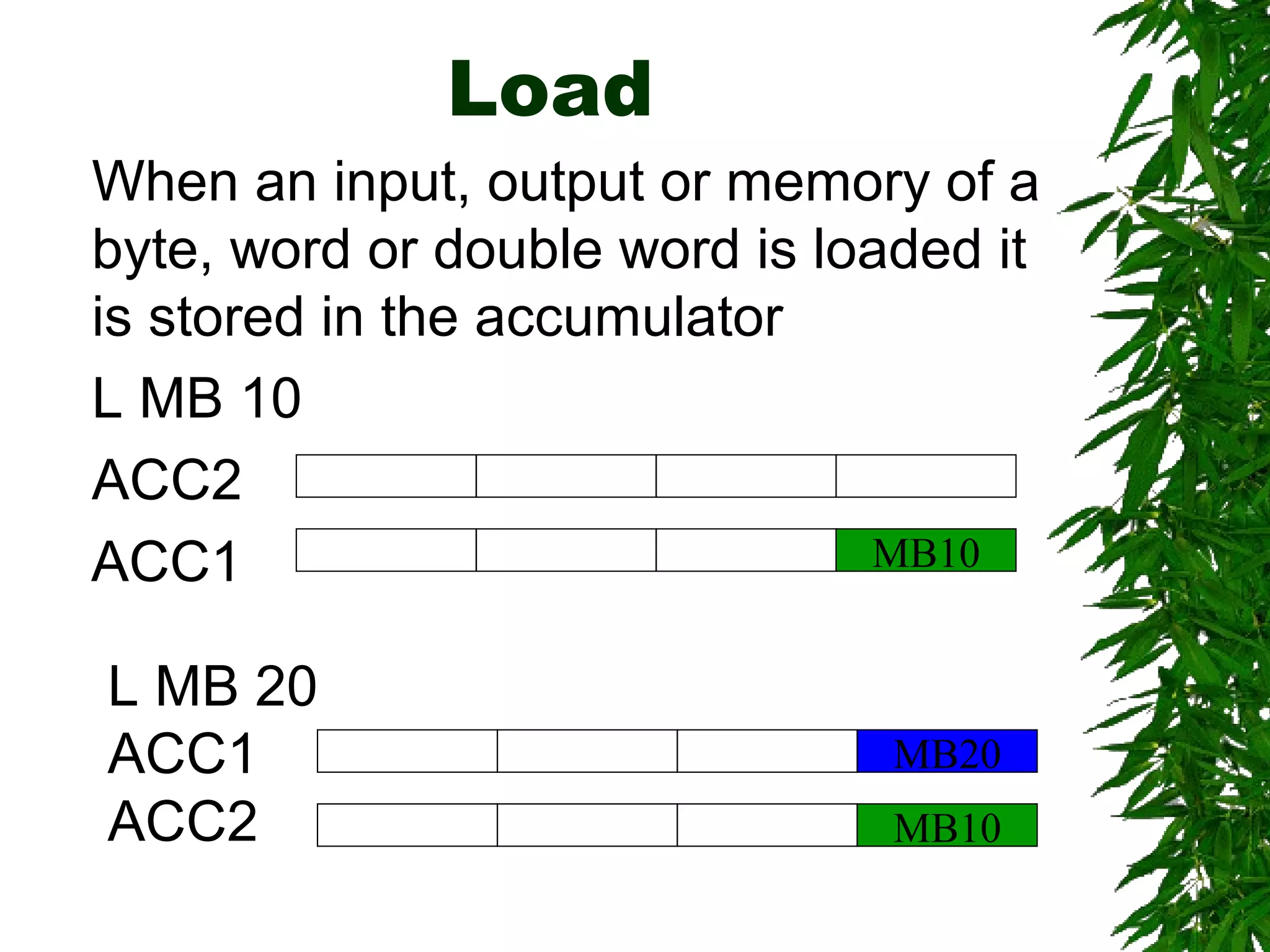
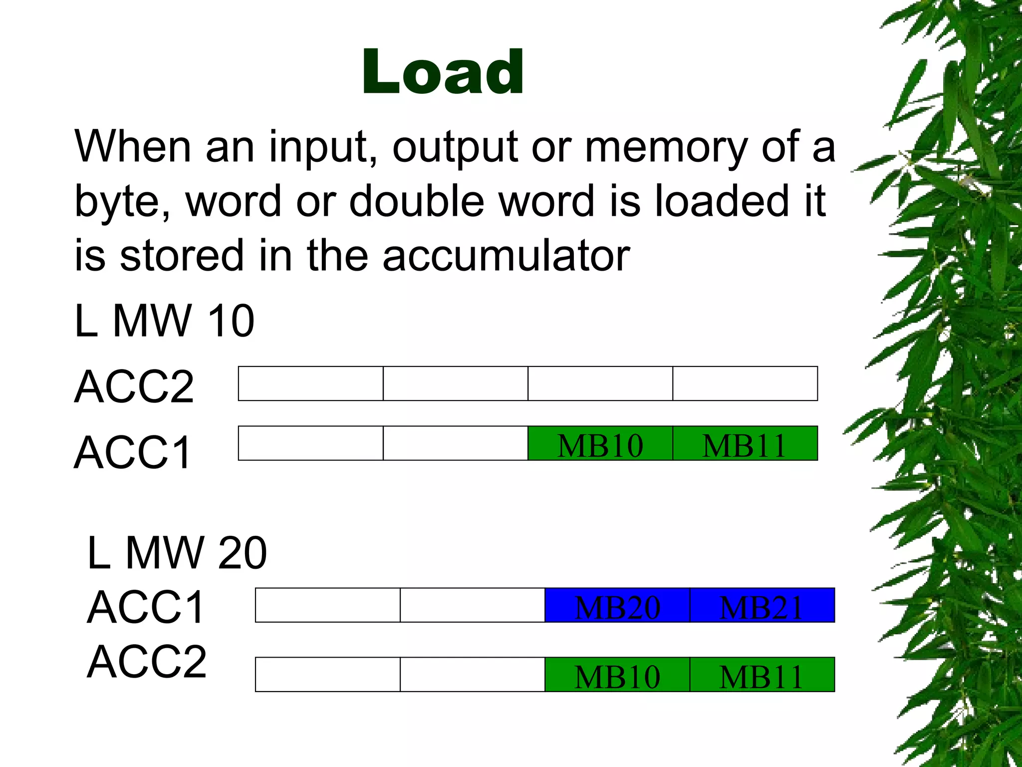
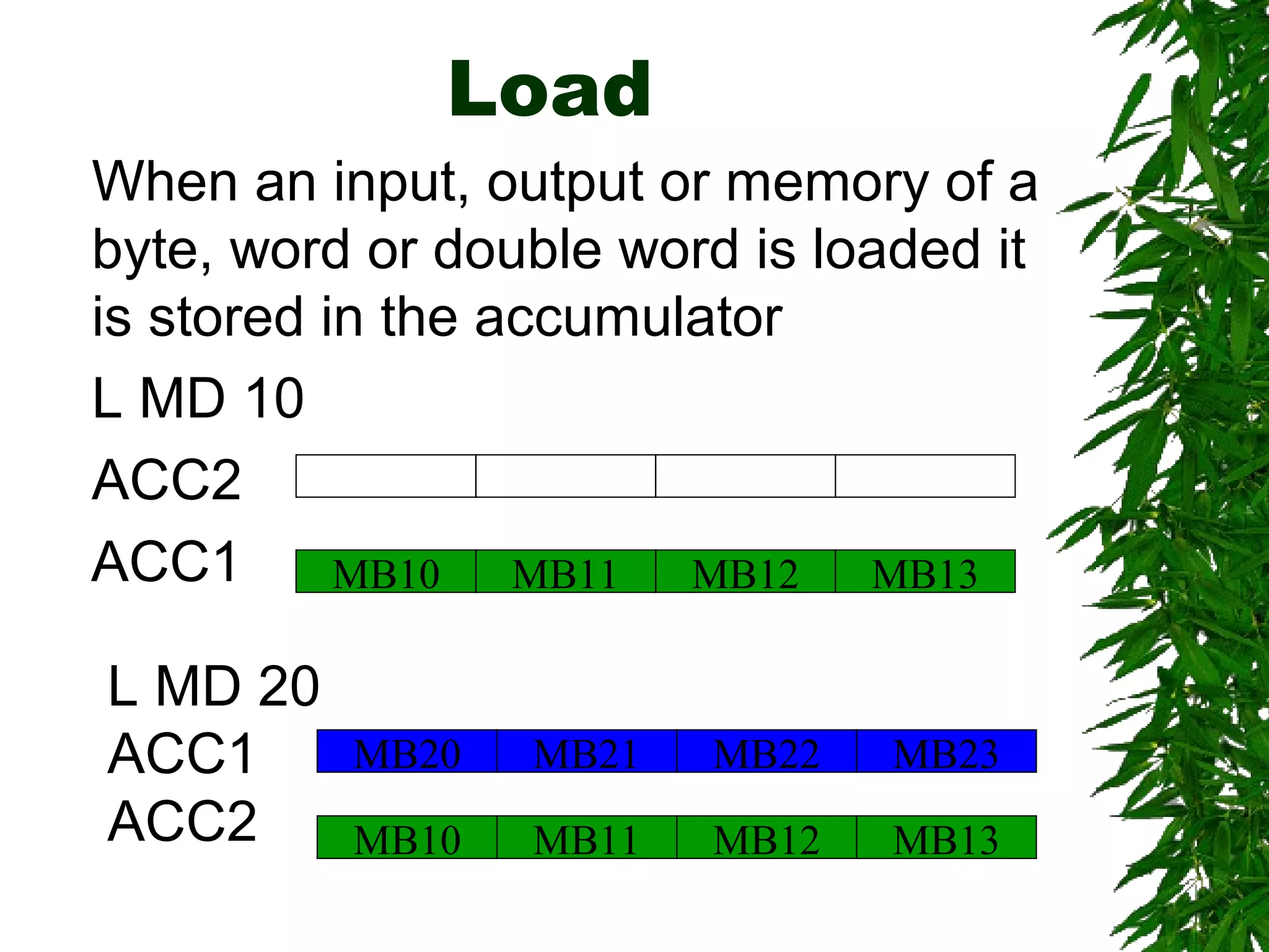
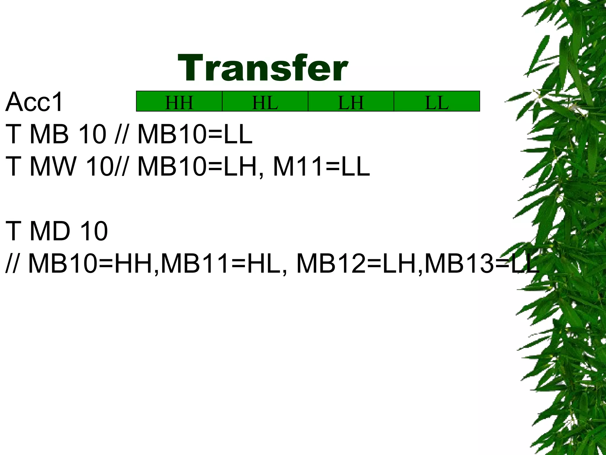
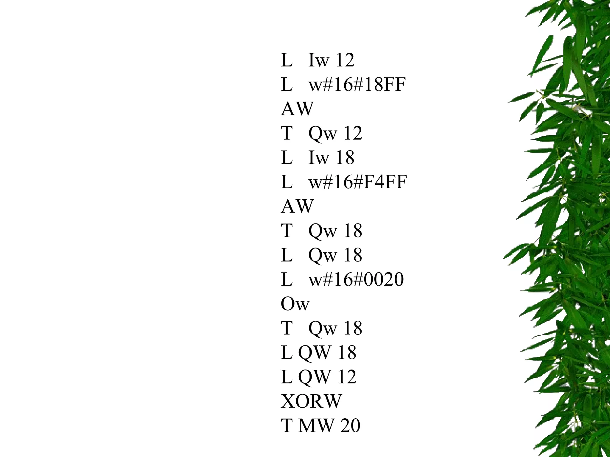
Design and
Programming Advanced
PLC
By
Dr. Palitha Dassanayake
Content
 Designing Advanced PLC
 Programming Advanced PLC
Industrial Applications on Automation
When a plant is to be replaced by Automation
we have to consider
Why?
Accuracy
Productivity
Cost
Other
How?
User requirements
System requirements
What to use?
Select Sensors, actuators and
control methods
Many automation plant uses PLC
Planning your
automation
Approach
Model Driven Approach
Component Based Approach
Model Driven Approach
Coupled with IT approach and UML
Component Based
automation
Component based automation (CBA), the decentralized
approach to automation with distributed intelligence in
technological modules, is picking up speed. Component
based automation clearly simplifies planning, engineering
and commissioning of complex plans and reduces the time
needed for the start of production by between 10% and 15%.
Planning your
automation
Main system requirements
Under this, the main requirement and functions
expected from the system has to be identified.
Outputs: Reports, UML based diagrams etc.
Component Selection
Design the system to match the main requirement
and fail safe design in terms of programming testing
as well as maintenance.
Industrial Survey could be very helpful
Outputs: Layout diagrams, component diagrams
Planning your
automation
Inclusion of monitoring and Control from higher levels
It should be identified the requirements of
monitoring and controlling from higher levels to
decide whether SCADA systems to be included or
not
Outputs: Report or UML format
Maintenance and Scheduling support
Preventive maintenance reminders, auto scheduling
requirements, historical records etc.
Outputs: Reports
PLC programming
Micro level Macro level
Macro-level Programming
Organizational Blocks
Programmable Blocks
Data blocks and Data words
Basics of designing a
program structure
The CPU run two programs
1. The operating system
2. User program
Operating Systems
 Handling start
 Update the process images
 Calling user programs
 Acquisition interrupt programs and calling
relevant OBs
 Error handling
 Memory Management
 Communicating with other devices
User program
 Specifying conditions to restart
 Processing process data
 Reactions to interrupt
 Handling disturbances in the normal
program cycle
Block Types S7-300
 Organization blocks
 Functions (FC)
 Function blocks (FB)
 Data Blocks
 System Function Blocks (SFB and
SFC)
Organization Blocks
 Main organization Block (OB1)
 Time of Day interrupts (OB10 to OB 17)
 Time Delay interrupts (OB 20 to OB 23)
 Cycle interrupts (OB 30 to OB 38)
 Hardware interrupts (OB 40 to OB 47)
 Start up (OB 100, OB 101 and OB 102)
Functions
 A logic block without memory. Temp.
variables are stacked on a local area
and lost after leaving the block.
 You can use data blocks to write
permanently.
Function Blocks
 Program with memory. An instance
data block is created with the function
block.
 By calling more than one IDB with one
FB you can get similar functions
working simultaneously.
Ex. Function Block (FB)
Formal parameter
Start INT IN
Speed INT IN
History DT IN_OUT
Run_time TIME IN_OUT
FB 20:Motor
Integer 16 Bits: Start
Integer 16 Bits: Speed
Data and Time : 48 bits
Time 32 bits: run time
Actual parameter
DB 202:Motor_2
FB Ex. Contd.
FB 21: Motor Processing
Variable declaration
Start Motor_1, FB 22
Start Motor_2, FB 22
Start Motor_3, FB 22
DB 100
Data for Motor_1
Data for Motor_2
Data for Motor_3
FB 22: Motors Call FB 21 from logic block
CALL FB 21,DB 100
Transfer data
CALL Motor_1
CALL Motor_2
CALL Motor_3
Data Blocks
FC 10
FC 11
FB 12
Shared DB
DB 20
(Access by all blocks
or any block)
Instance DB
DB 112
(access only by
FB 12)
SFC and SFB
They are in built functions and functions
Blocks that can be used.
Use of Word logic
L MW 30
L MW 28
OW
T MW 32
L MW 60
L MW 64
AW
T MW 10
L MW 16
L MW 12
XORW
T MW 40
Load
When an input, output or memory of a
byte, word or double word is loaded it
is stored in the accumulator
L MB 10
ACC2
ACC1 MB10
L MB 20
ACC1
ACC2 MB10
MB20
Load
L MW 20
ACC1
ACC2
MB21
MB11MB10
MB20
MB11MB10
When an input, output or memory of a
byte, word or double word is loaded it
is stored in the accumulator
L MW 10
ACC2
ACC1
Load
L MD 20
ACC1
ACC2
MB23MB22MB21MB20
MB13MB12MB11MB10
MB13MB12MB11MB10
When an input, output or memory of a
byte, word or double word is loaded it
is stored in the accumulator
L MD 10
ACC2
ACC1
Transfer
LLLHHLHHAcc1
T MB 10 // MB10=LL
T MW 10// MB10=LH, M11=LL
T MD 10
// MB10=HH,MB11=HL, MB12=LH,MB13=LL
L Iw 12
L w#16#18FF
AW
T Qw 12
L Iw 18
L w#16#F4FF
AW
T Qw 18
L Qw 18
L w#16#0020
Ow
T Qw 18
L QW 18
L QW 12
XORW
T MW 20
END

Automationcontrol7

  • 1.
  • 2.
    Content  Designing AdvancedPLC  Programming Advanced PLC
  • 3.
    Industrial Applications onAutomation When a plant is to be replaced by Automation we have to consider Why? Accuracy Productivity Cost Other How? User requirements System requirements What to use? Select Sensors, actuators and control methods Many automation plant uses PLC
  • 4.
    Planning your automation Approach Model DrivenApproach Component Based Approach
  • 5.
    Model Driven Approach Coupledwith IT approach and UML
  • 6.
    Component Based automation Component basedautomation (CBA), the decentralized approach to automation with distributed intelligence in technological modules, is picking up speed. Component based automation clearly simplifies planning, engineering and commissioning of complex plans and reduces the time needed for the start of production by between 10% and 15%.
  • 7.
    Planning your automation Main systemrequirements Under this, the main requirement and functions expected from the system has to be identified. Outputs: Reports, UML based diagrams etc. Component Selection Design the system to match the main requirement and fail safe design in terms of programming testing as well as maintenance. Industrial Survey could be very helpful Outputs: Layout diagrams, component diagrams
  • 8.
    Planning your automation Inclusion ofmonitoring and Control from higher levels It should be identified the requirements of monitoring and controlling from higher levels to decide whether SCADA systems to be included or not Outputs: Report or UML format Maintenance and Scheduling support Preventive maintenance reminders, auto scheduling requirements, historical records etc. Outputs: Reports
  • 9.
    PLC programming Micro levelMacro level Macro-level Programming Organizational Blocks Programmable Blocks Data blocks and Data words
  • 10.
    Basics of designinga program structure The CPU run two programs 1. The operating system 2. User program
  • 11.
    Operating Systems  Handlingstart  Update the process images  Calling user programs  Acquisition interrupt programs and calling relevant OBs  Error handling  Memory Management  Communicating with other devices
  • 12.
    User program  Specifyingconditions to restart  Processing process data  Reactions to interrupt  Handling disturbances in the normal program cycle
  • 13.
    Block Types S7-300 Organization blocks  Functions (FC)  Function blocks (FB)  Data Blocks  System Function Blocks (SFB and SFC)
  • 14.
    Organization Blocks  Mainorganization Block (OB1)  Time of Day interrupts (OB10 to OB 17)  Time Delay interrupts (OB 20 to OB 23)  Cycle interrupts (OB 30 to OB 38)  Hardware interrupts (OB 40 to OB 47)  Start up (OB 100, OB 101 and OB 102)
  • 15.
    Functions  A logicblock without memory. Temp. variables are stacked on a local area and lost after leaving the block.  You can use data blocks to write permanently.
  • 16.
    Function Blocks  Programwith memory. An instance data block is created with the function block.  By calling more than one IDB with one FB you can get similar functions working simultaneously.
  • 17.
    Ex. Function Block(FB) Formal parameter Start INT IN Speed INT IN History DT IN_OUT Run_time TIME IN_OUT FB 20:Motor Integer 16 Bits: Start Integer 16 Bits: Speed Data and Time : 48 bits Time 32 bits: run time Actual parameter DB 202:Motor_2
  • 18.
    FB Ex. Contd. FB21: Motor Processing Variable declaration Start Motor_1, FB 22 Start Motor_2, FB 22 Start Motor_3, FB 22 DB 100 Data for Motor_1 Data for Motor_2 Data for Motor_3 FB 22: Motors Call FB 21 from logic block CALL FB 21,DB 100 Transfer data CALL Motor_1 CALL Motor_2 CALL Motor_3
  • 19.
    Data Blocks FC 10 FC11 FB 12 Shared DB DB 20 (Access by all blocks or any block) Instance DB DB 112 (access only by FB 12)
  • 20.
    SFC and SFB Theyare in built functions and functions Blocks that can be used.
  • 21.
    Use of Wordlogic L MW 30 L MW 28 OW T MW 32 L MW 60 L MW 64 AW T MW 10 L MW 16 L MW 12 XORW T MW 40
  • 22.
    Load When an input,output or memory of a byte, word or double word is loaded it is stored in the accumulator L MB 10 ACC2 ACC1 MB10 L MB 20 ACC1 ACC2 MB10 MB20
  • 23.
    Load L MW 20 ACC1 ACC2 MB21 MB11MB10 MB20 MB11MB10 Whenan input, output or memory of a byte, word or double word is loaded it is stored in the accumulator L MW 10 ACC2 ACC1
  • 24.
    Load L MD 20 ACC1 ACC2 MB23MB22MB21MB20 MB13MB12MB11MB10 MB13MB12MB11MB10 Whenan input, output or memory of a byte, word or double word is loaded it is stored in the accumulator L MD 10 ACC2 ACC1
  • 25.
    Transfer LLLHHLHHAcc1 T MB 10// MB10=LL T MW 10// MB10=LH, M11=LL T MD 10 // MB10=HH,MB11=HL, MB12=LH,MB13=LL
  • 26.
    L Iw 12 Lw#16#18FF AW T Qw 12 L Iw 18 L w#16#F4FF AW T Qw 18 L Qw 18 L w#16#0020 Ow T Qw 18 L QW 18 L QW 12 XORW T MW 20
  • 27.