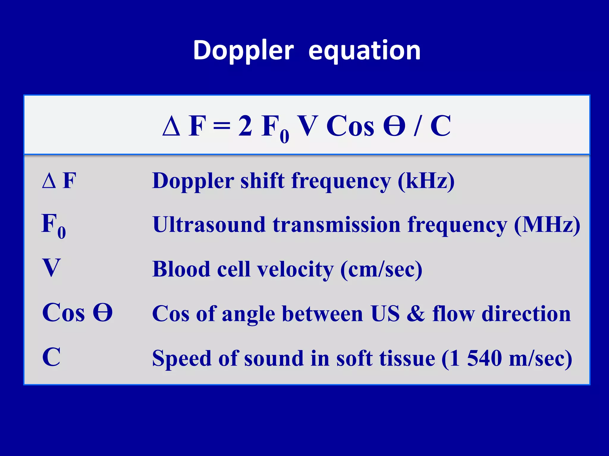
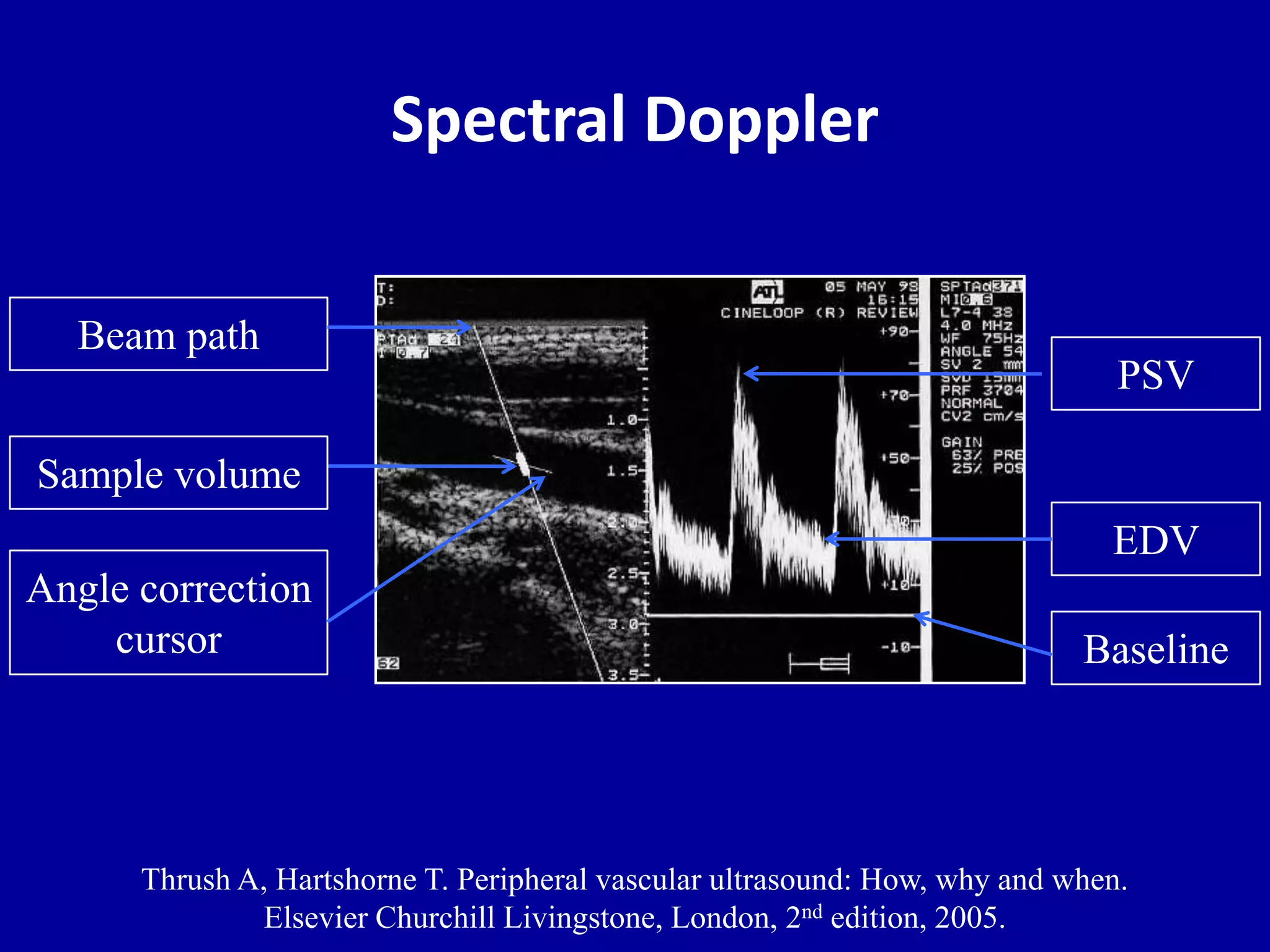
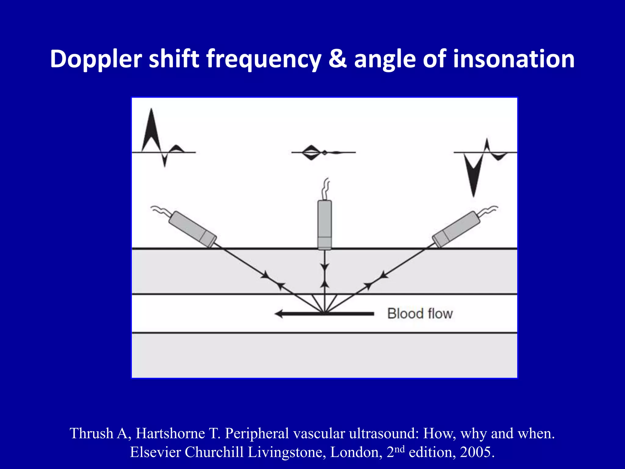
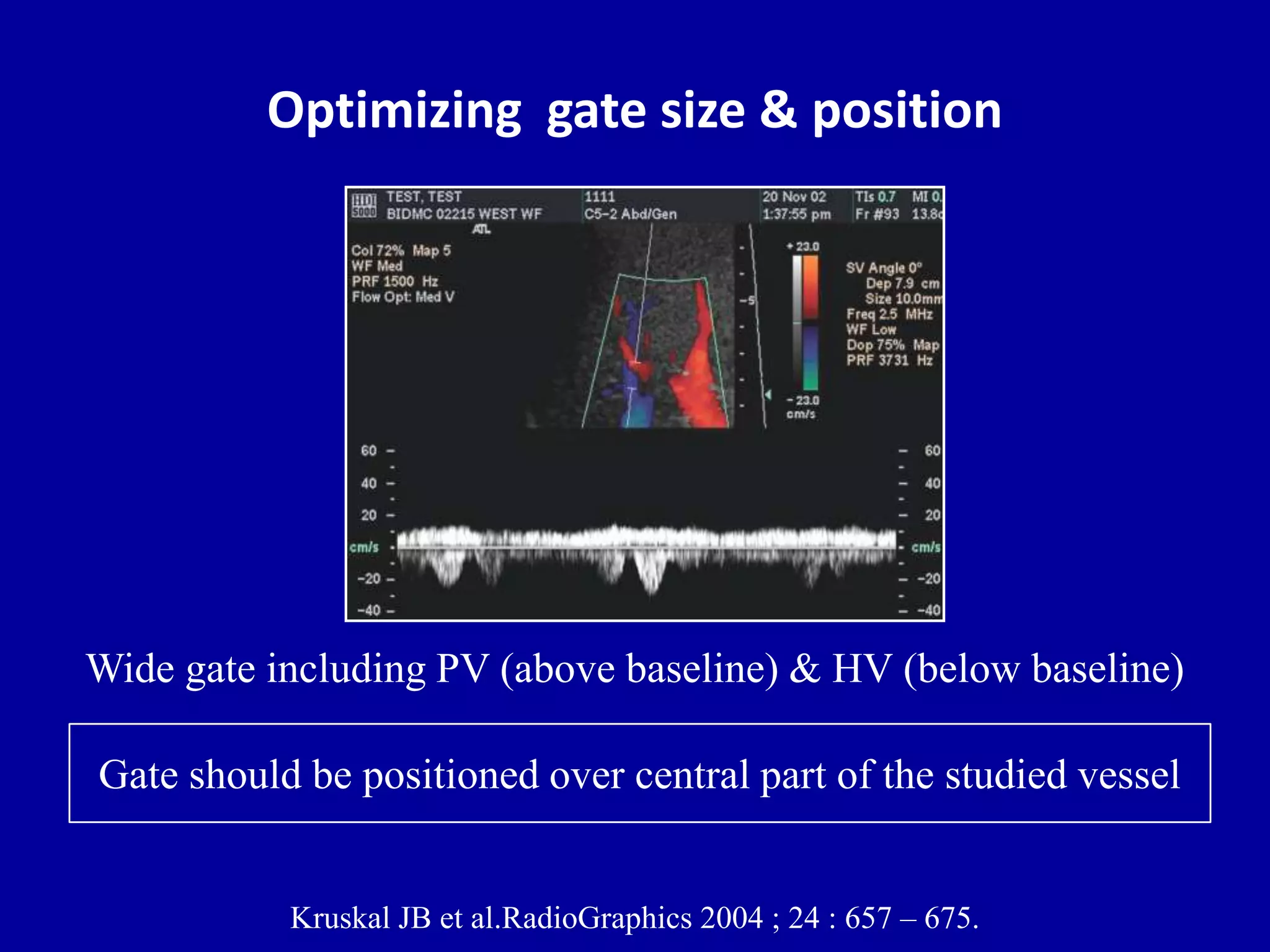
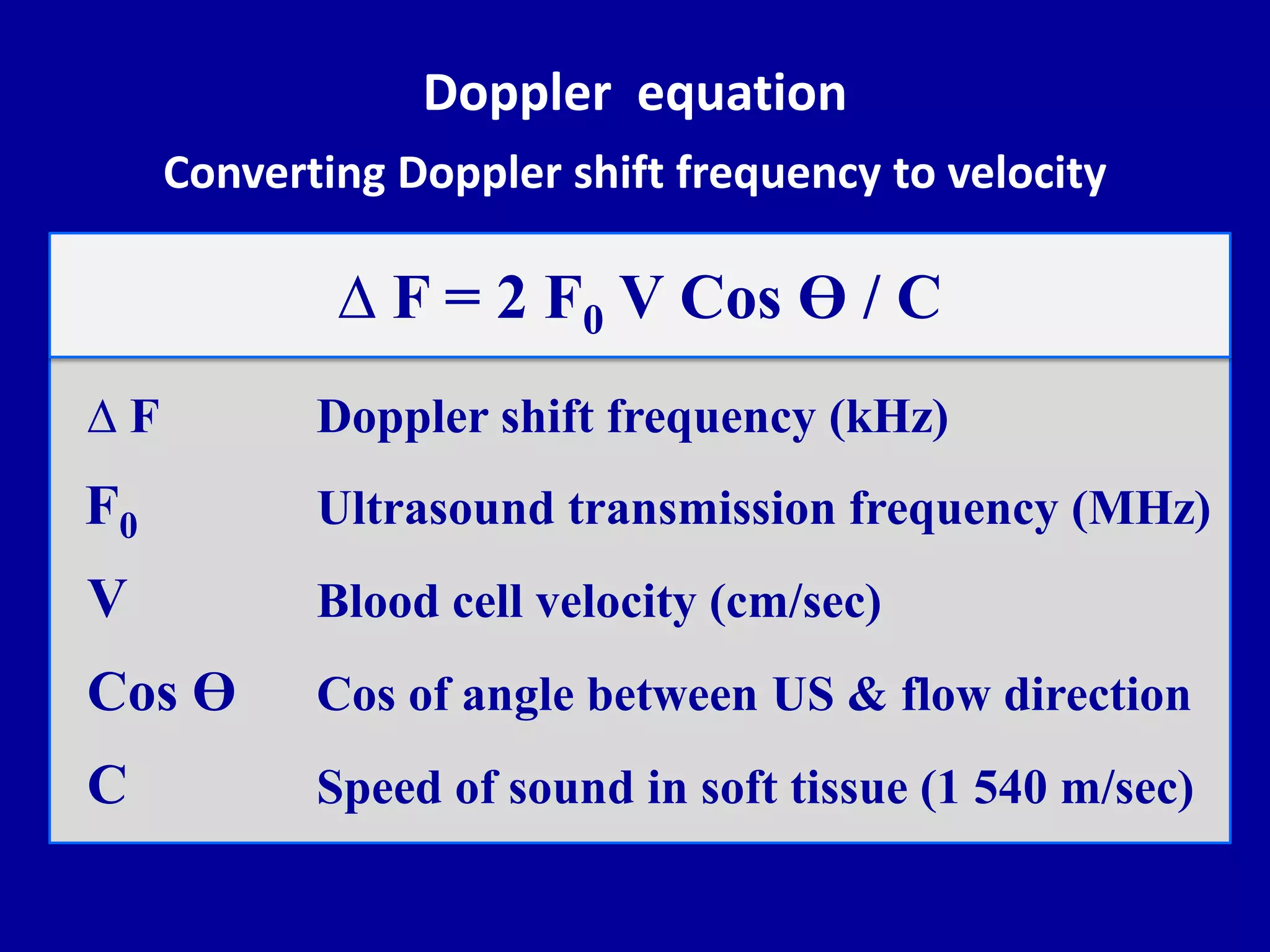
This document discusses the principles of Doppler ultrasound. It begins with a brief history of Doppler and how the Doppler effect was discovered. It then covers the basic physics of Doppler ultrasound including the Doppler equation. The remainder of the document discusses specific Doppler parameters and how to optimize the Doppler examination including:
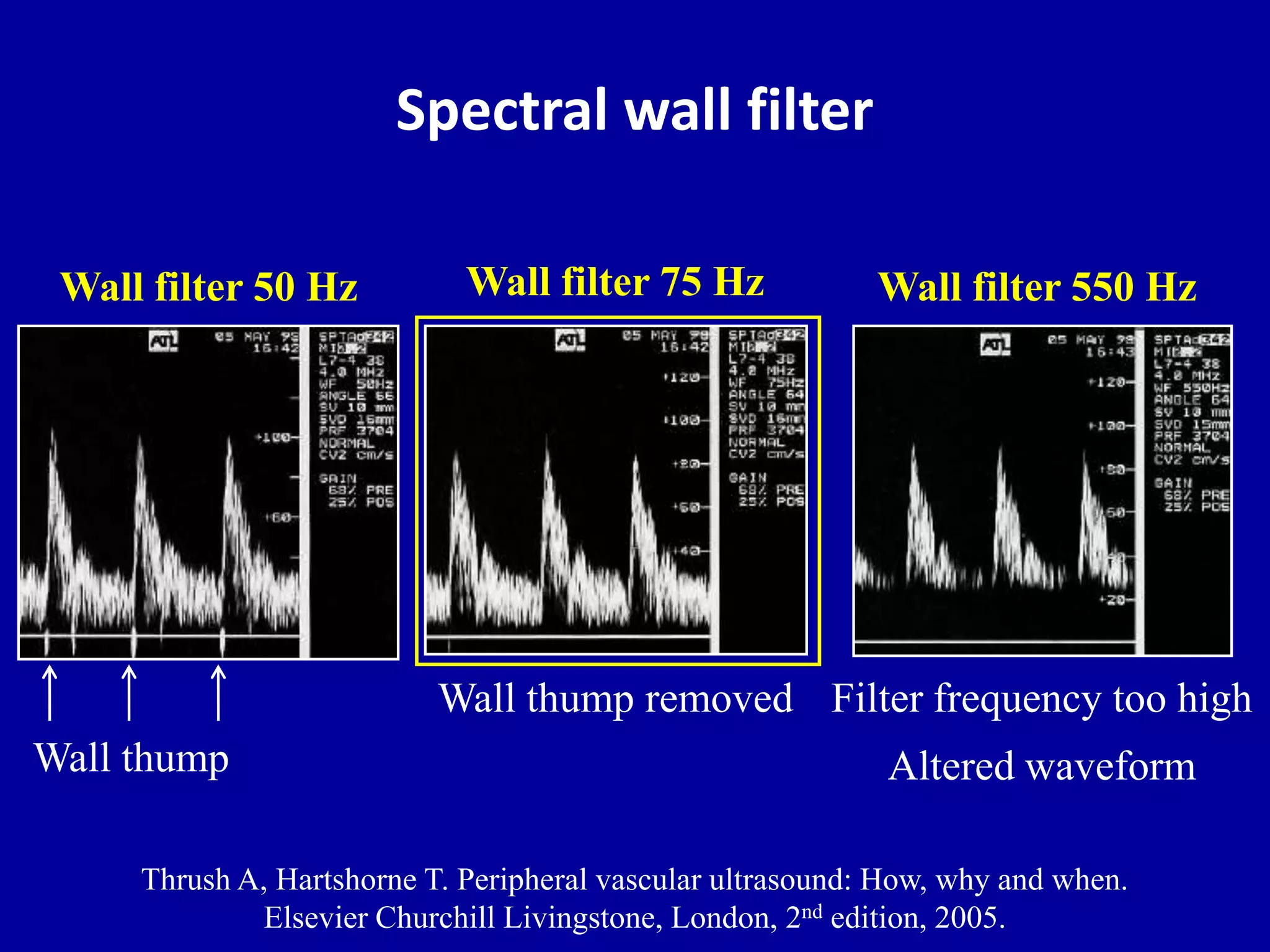
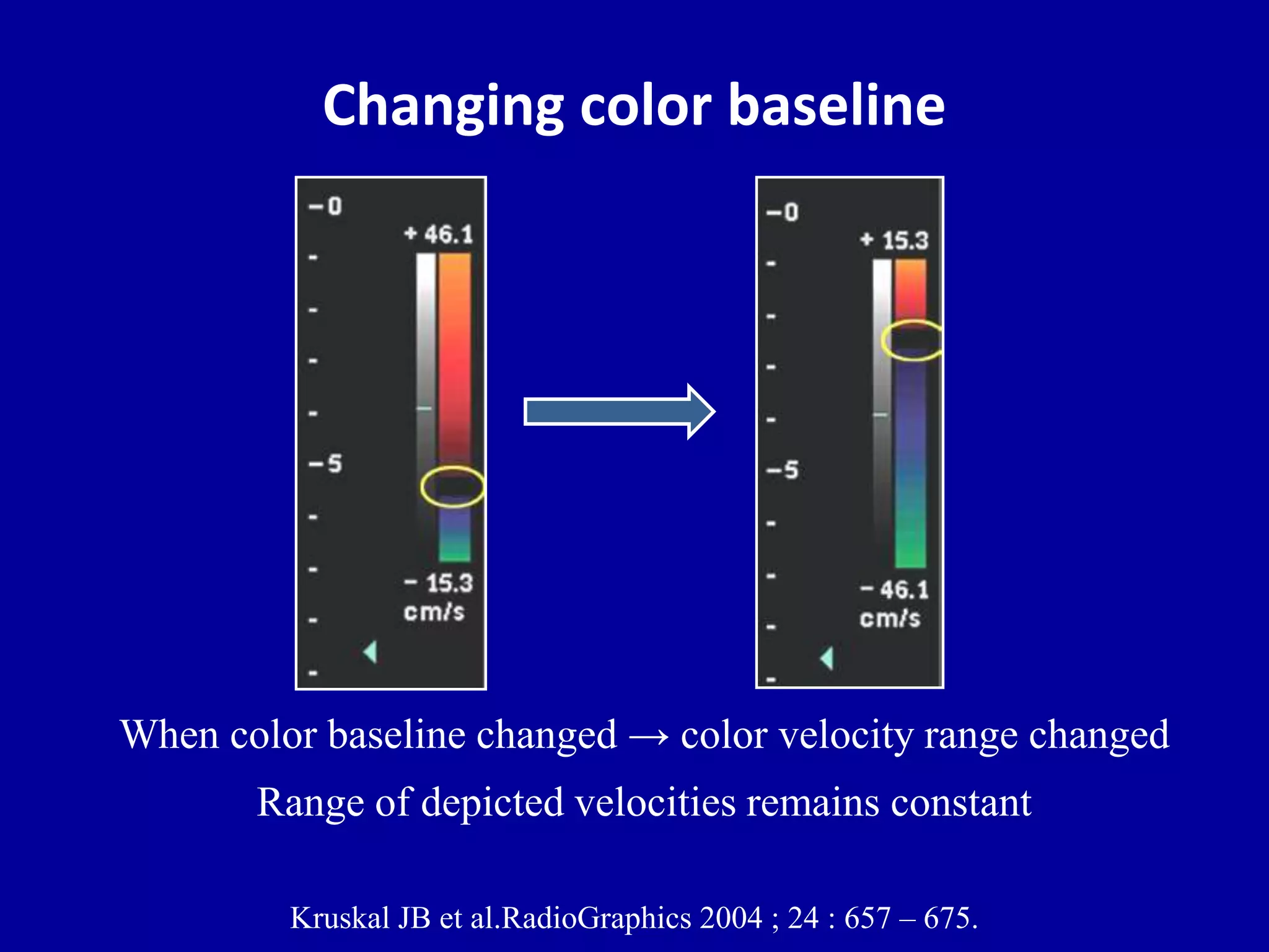
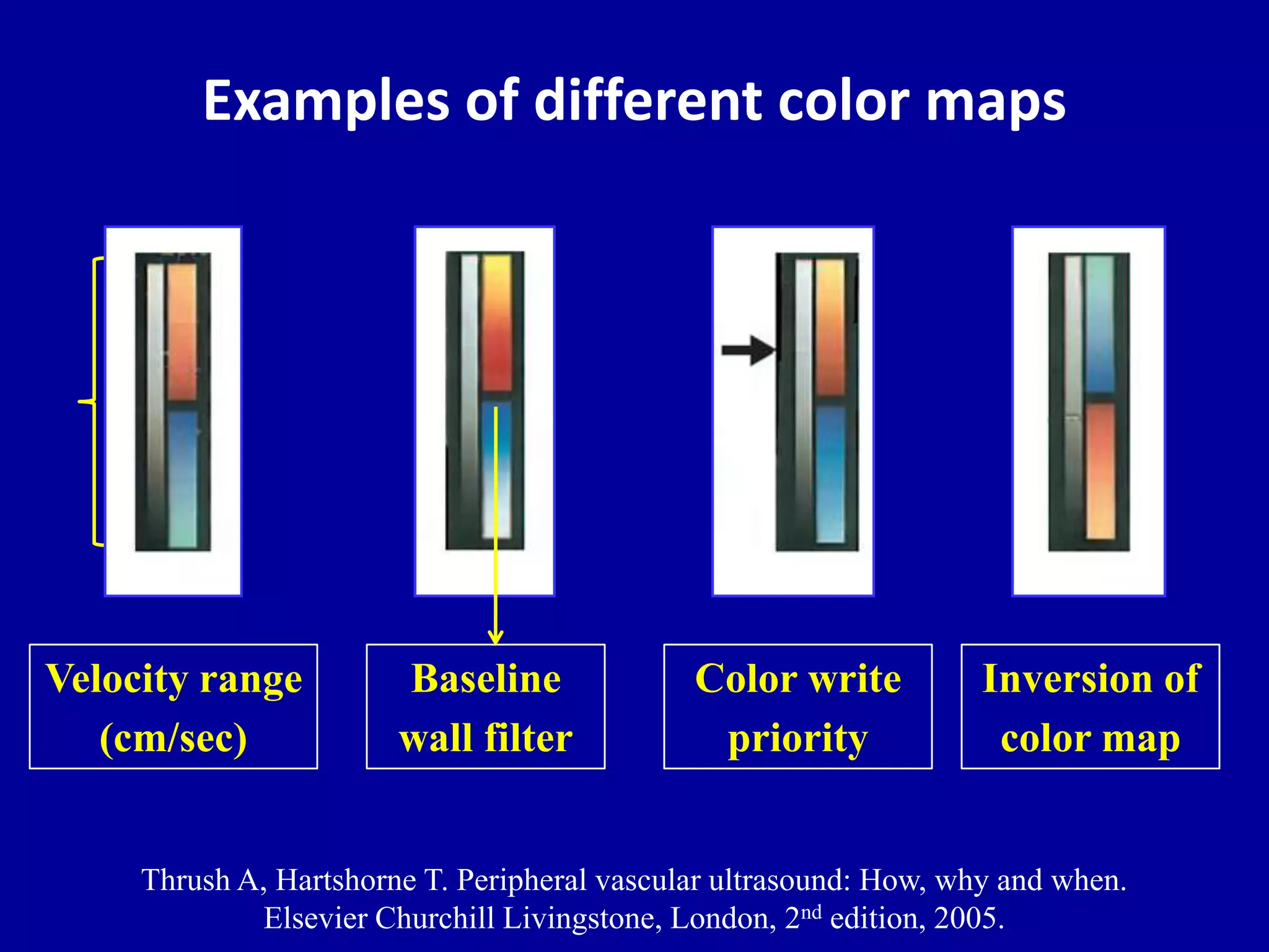
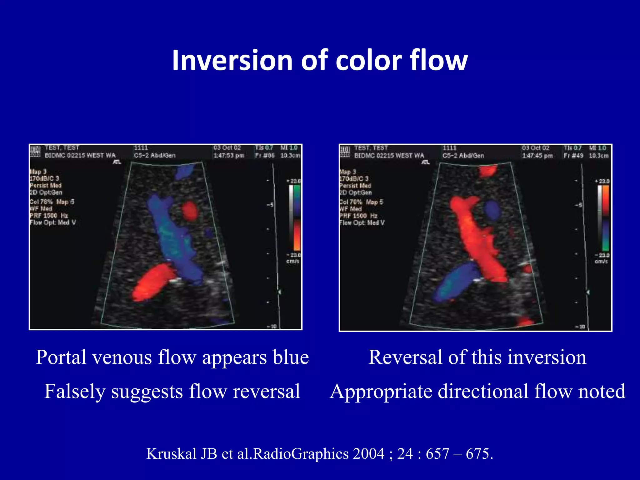
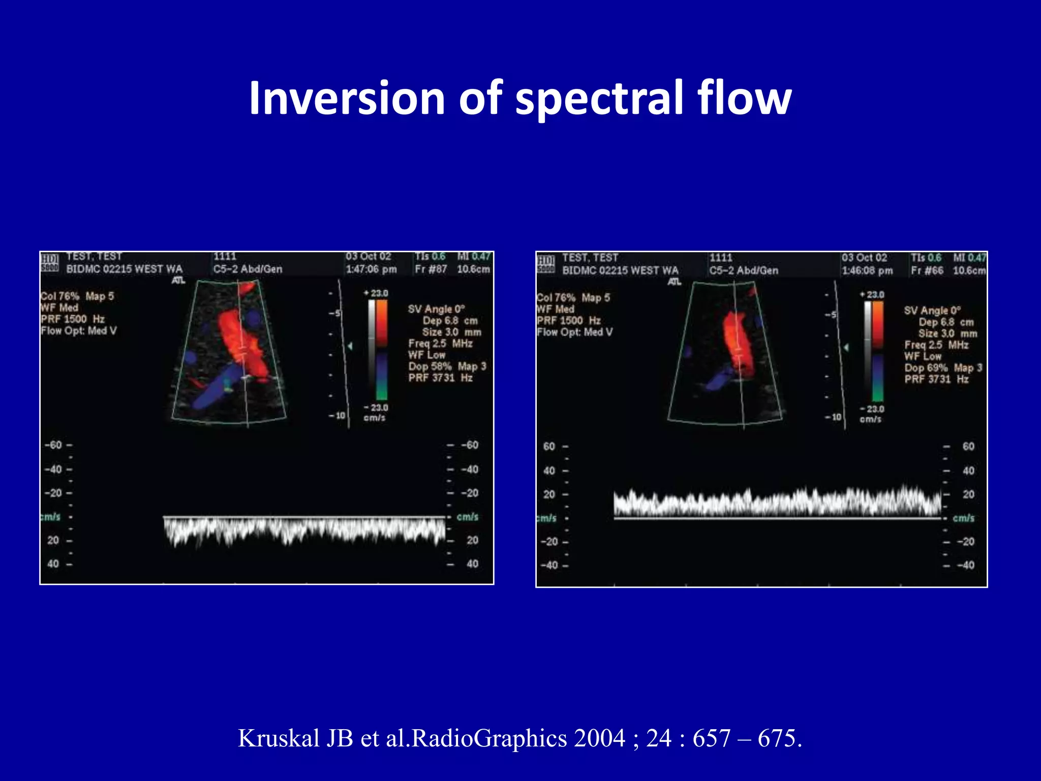
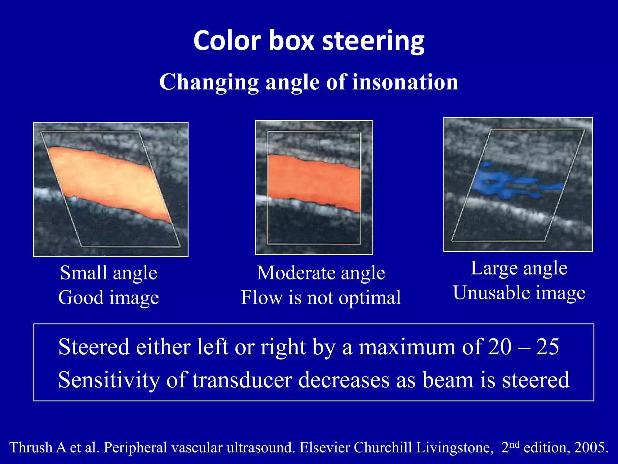
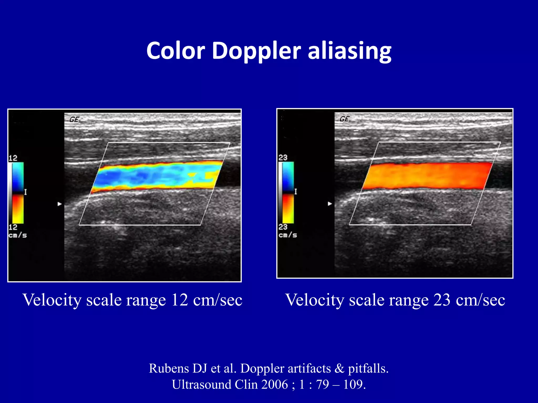
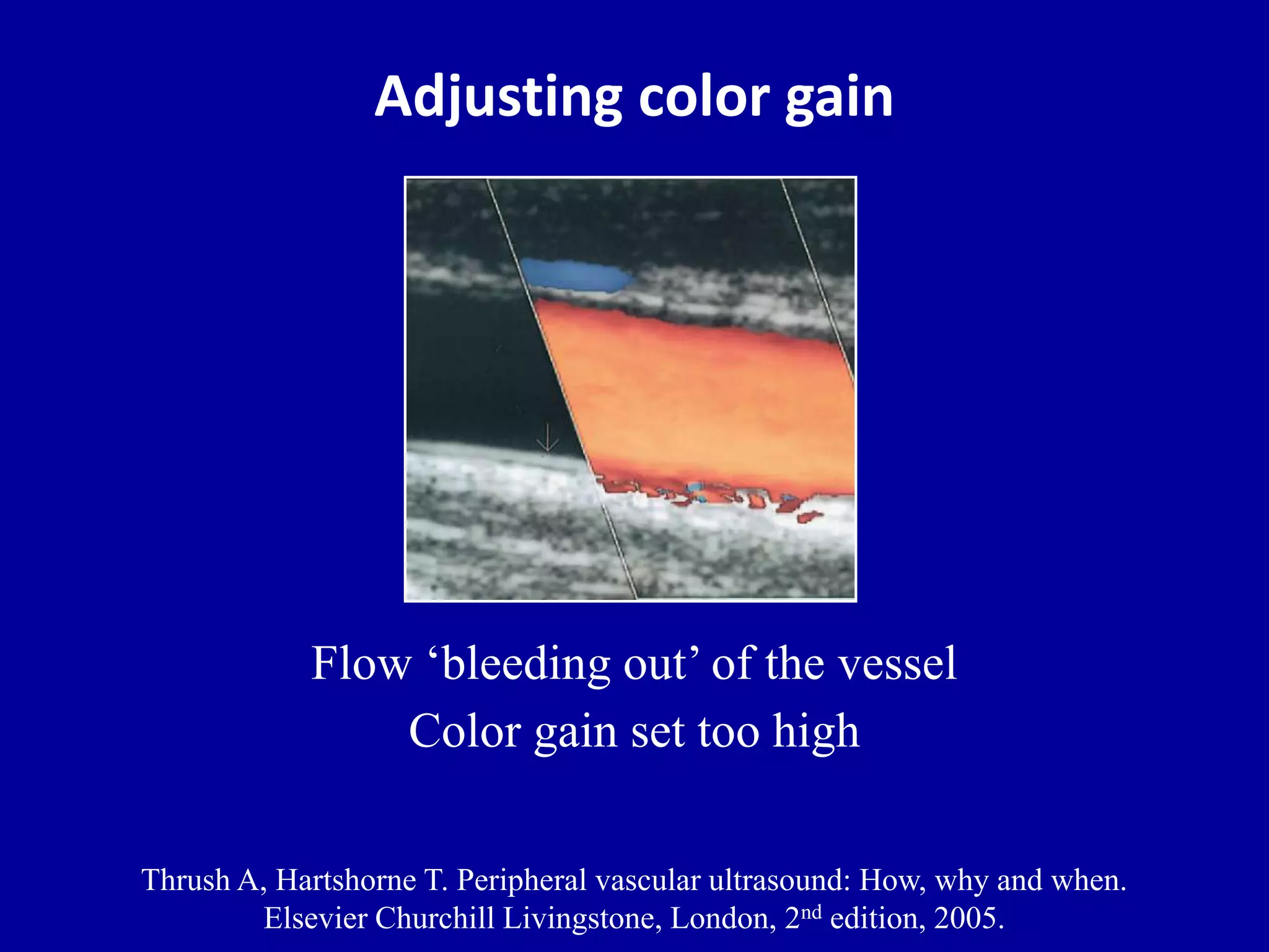
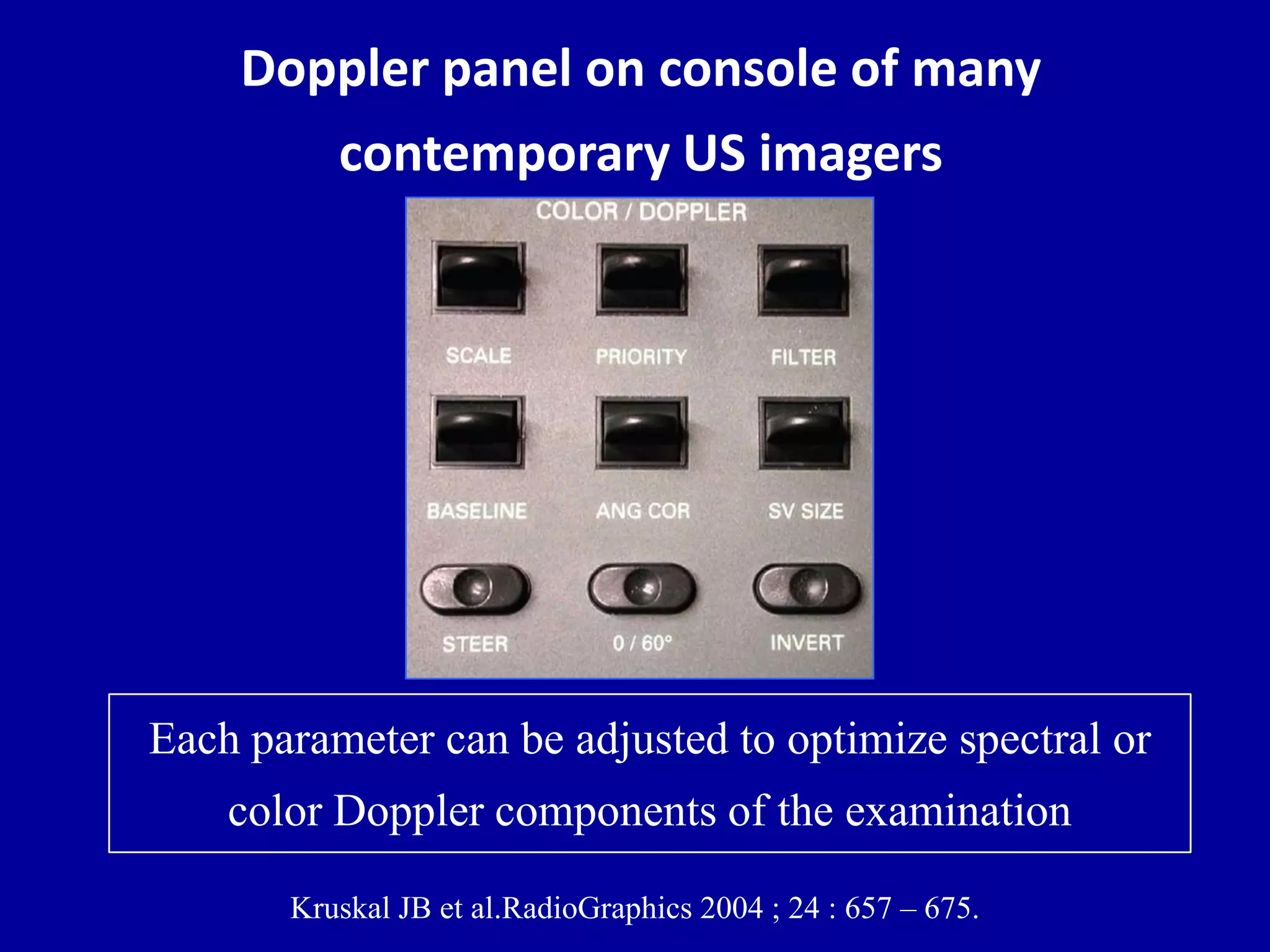
- Adjusting spectral and color Doppler parameters
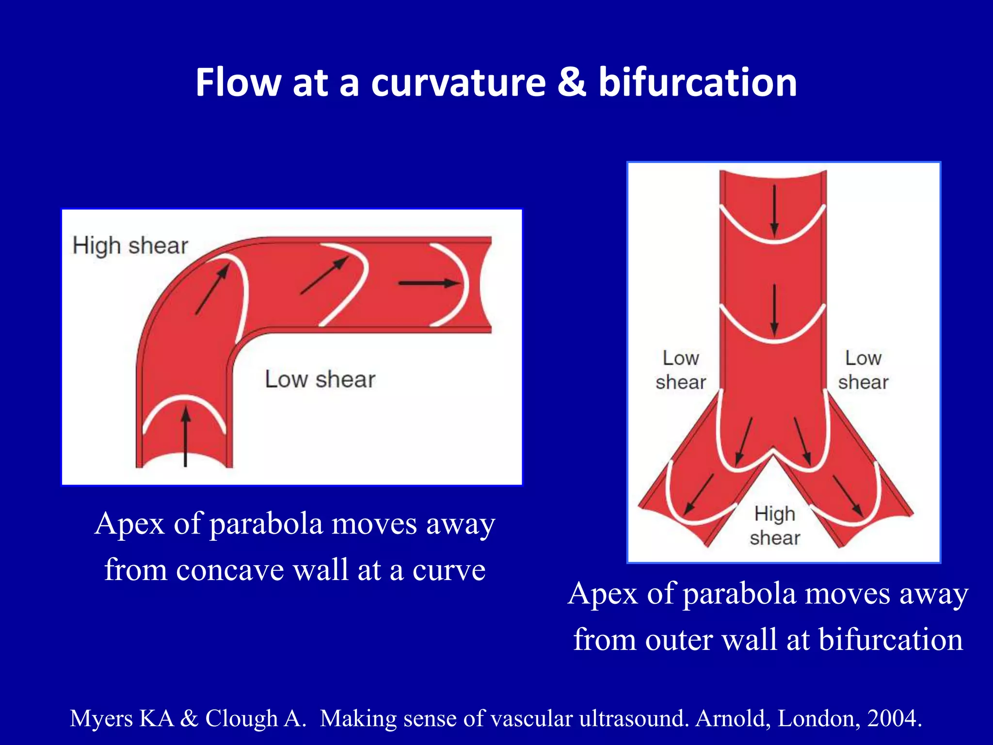
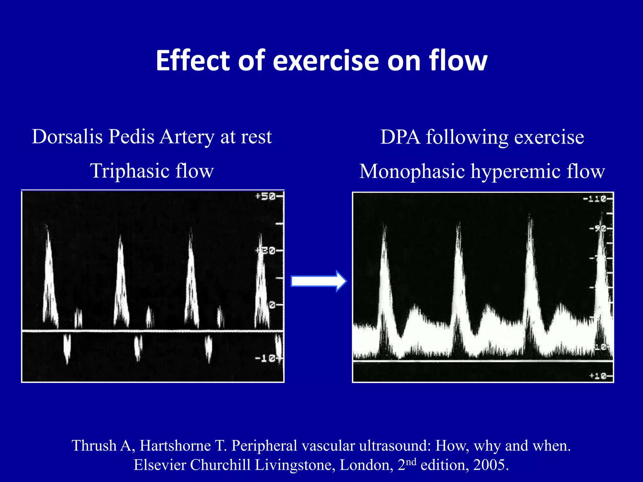
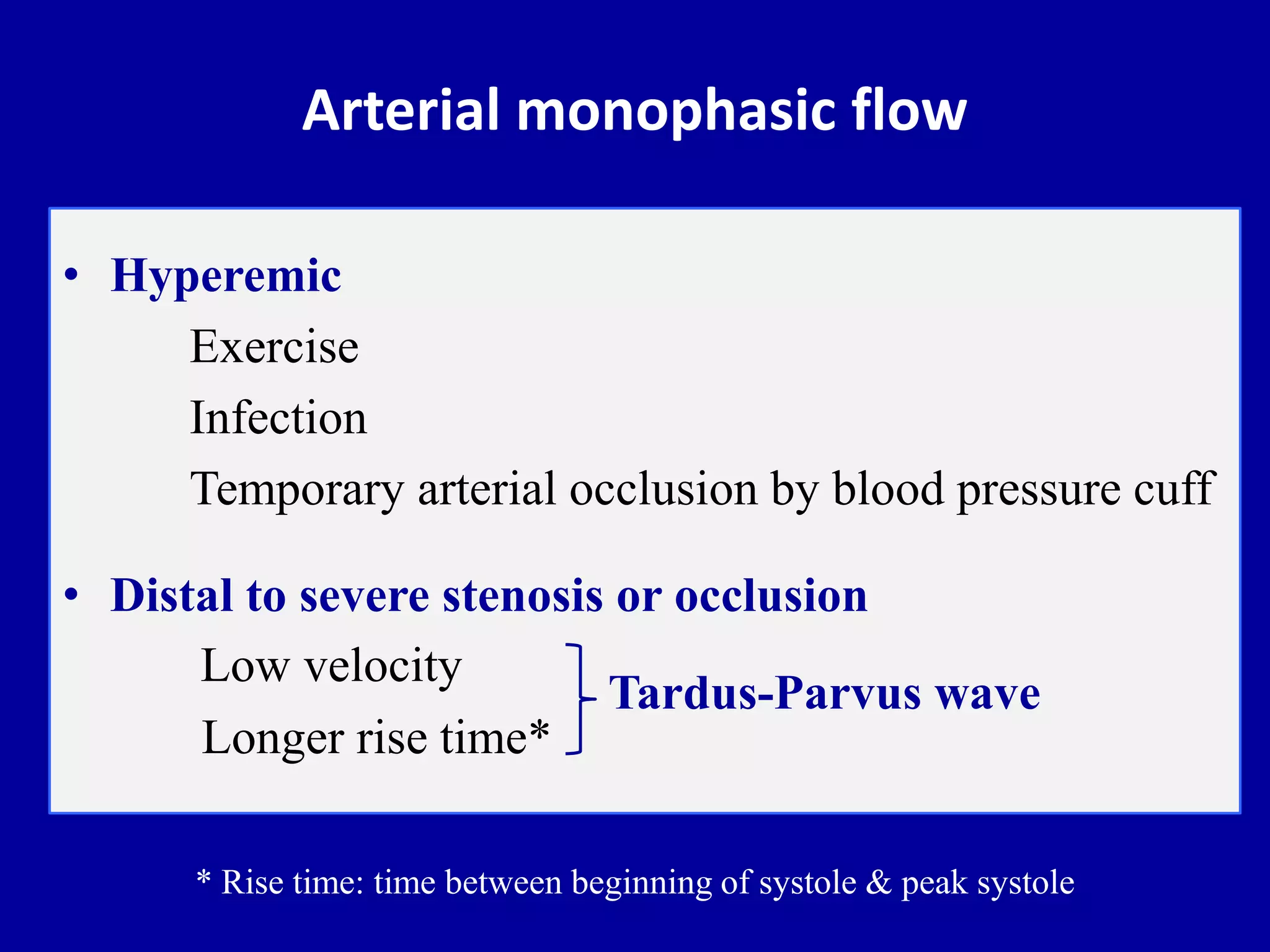
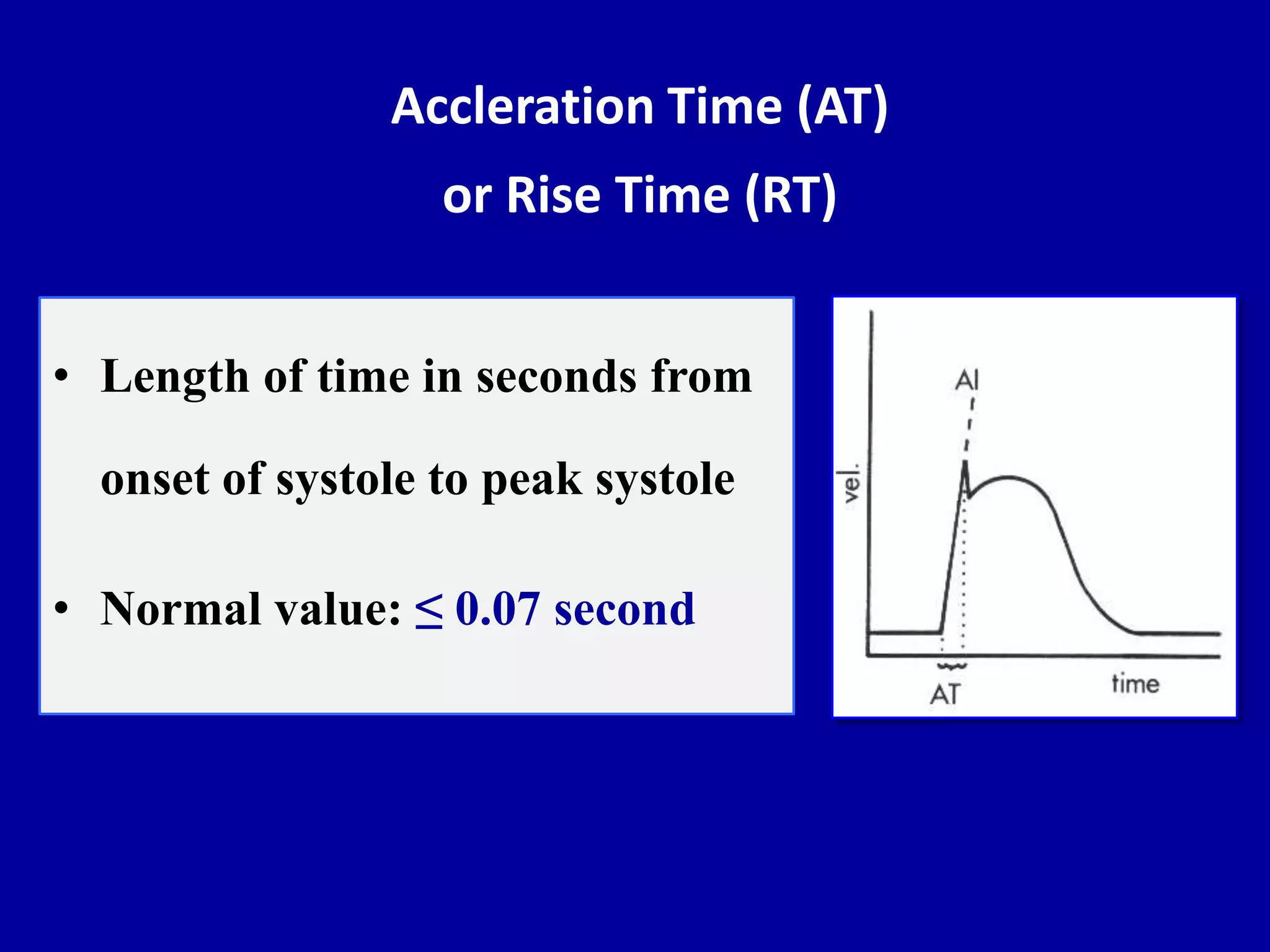
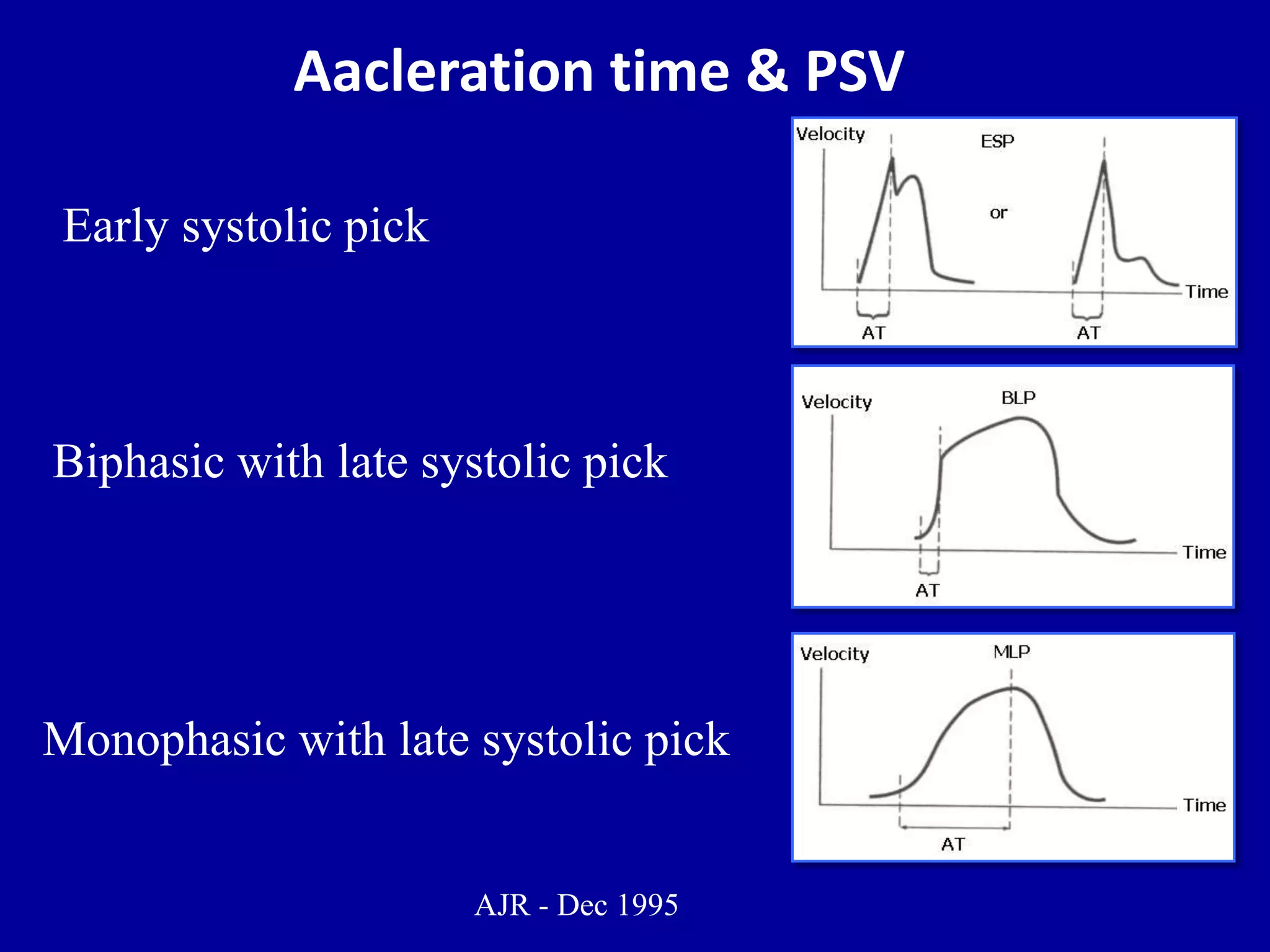
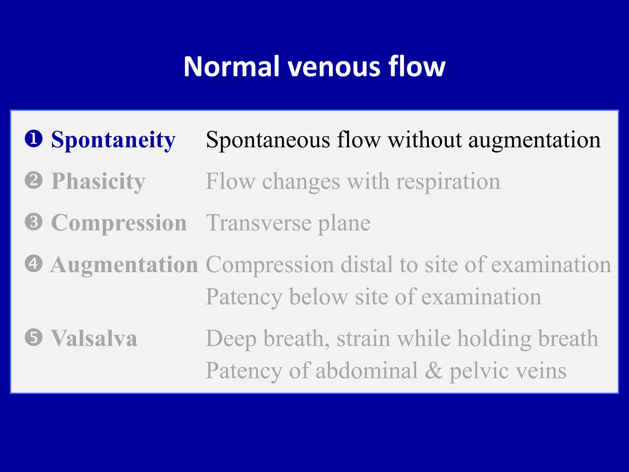
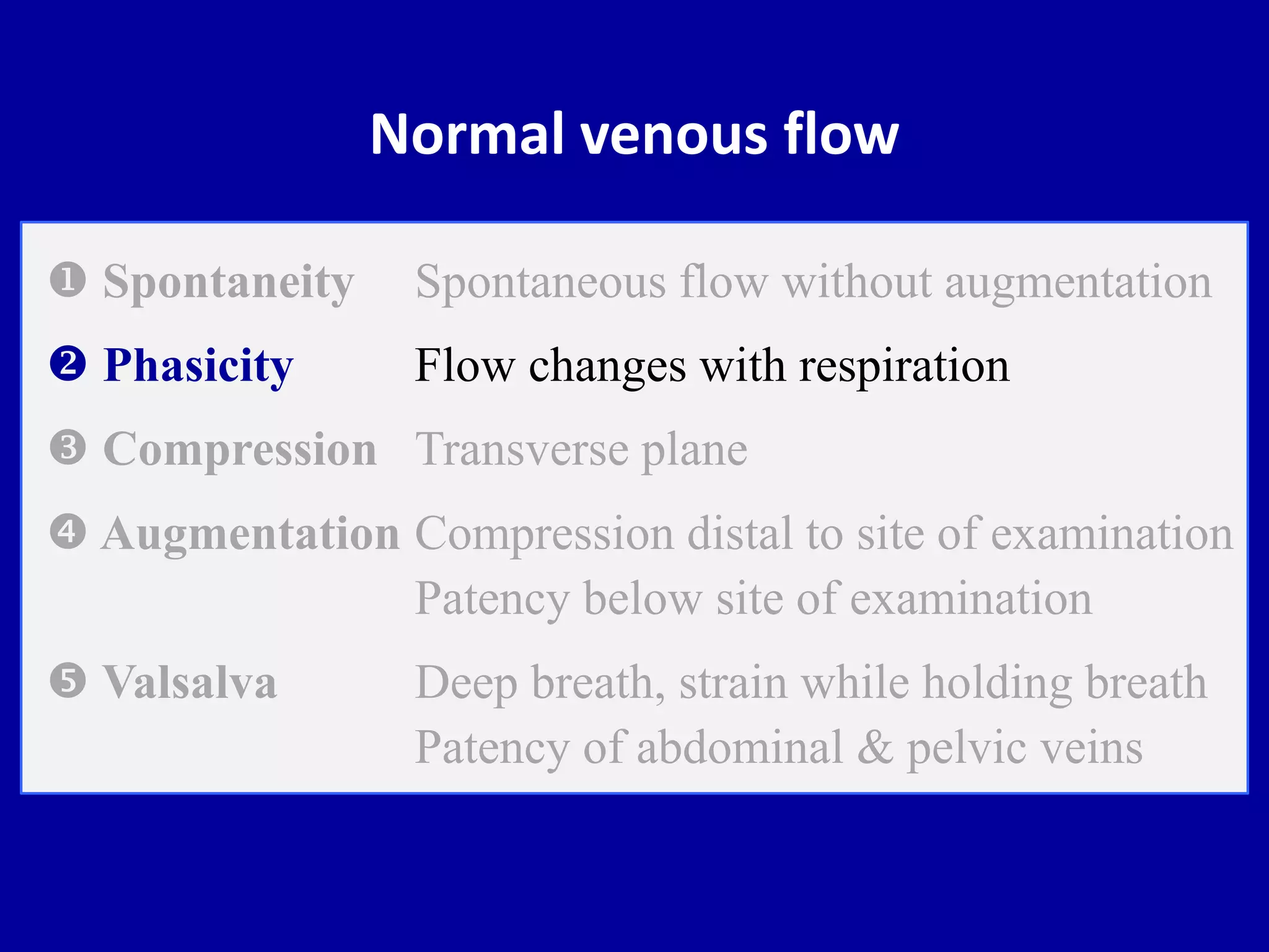
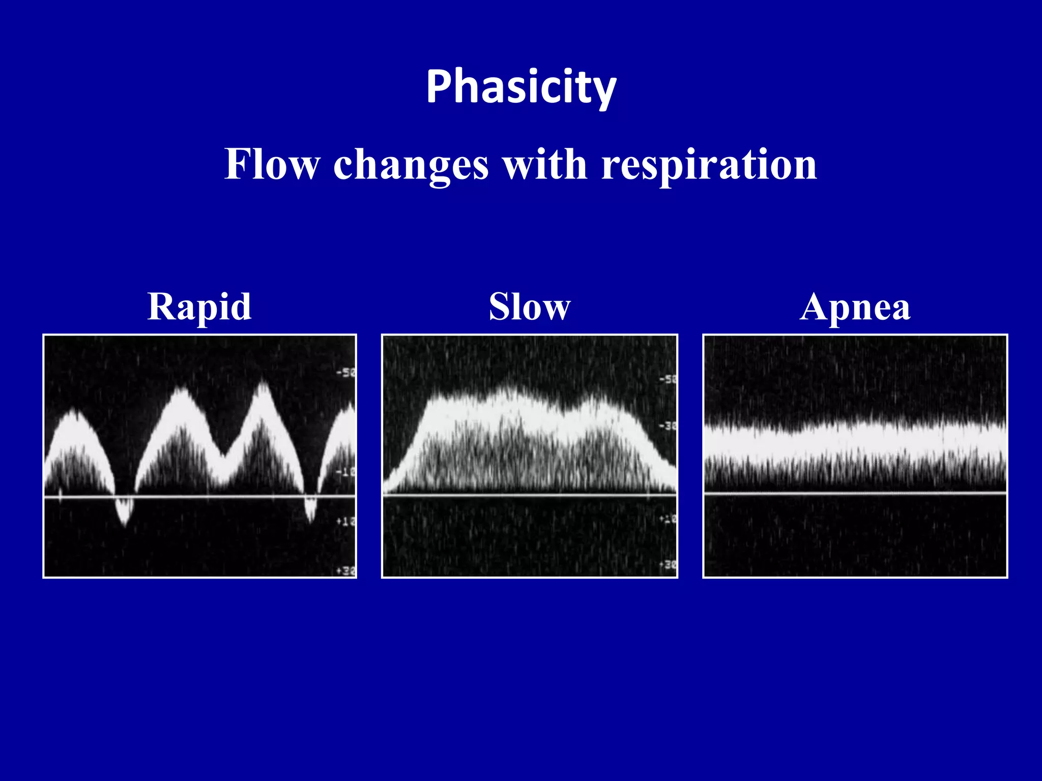
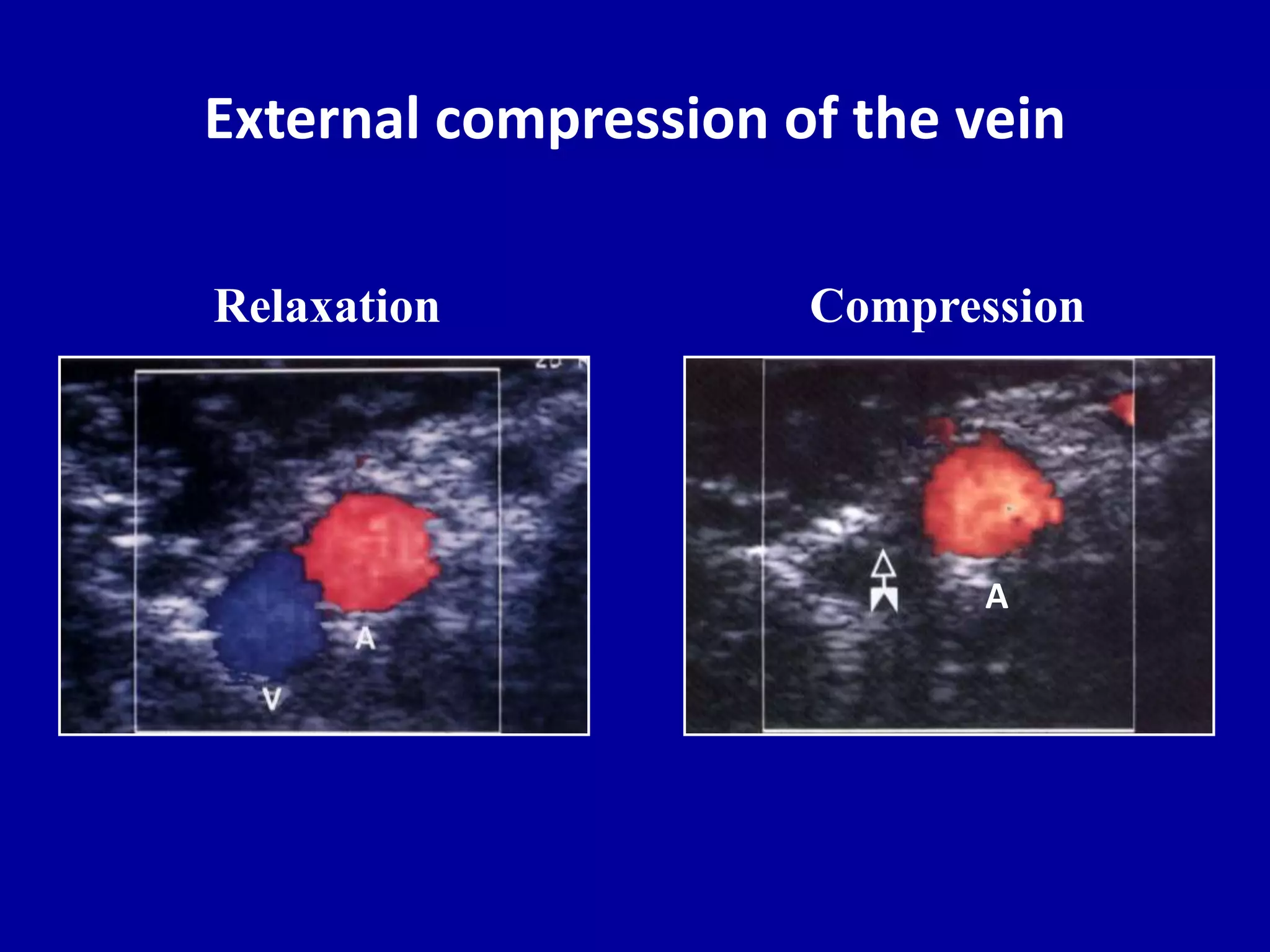
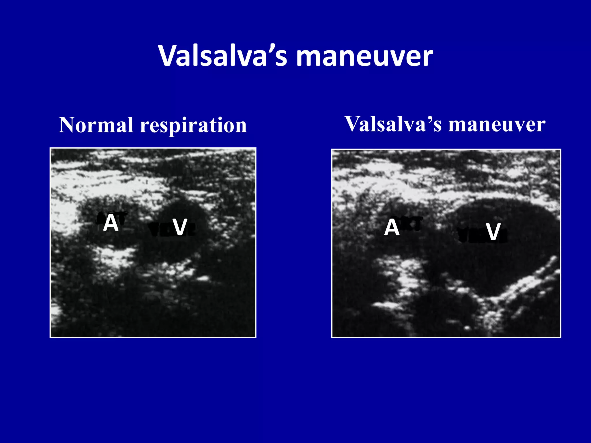
- Normal arterial and venous flow patterns
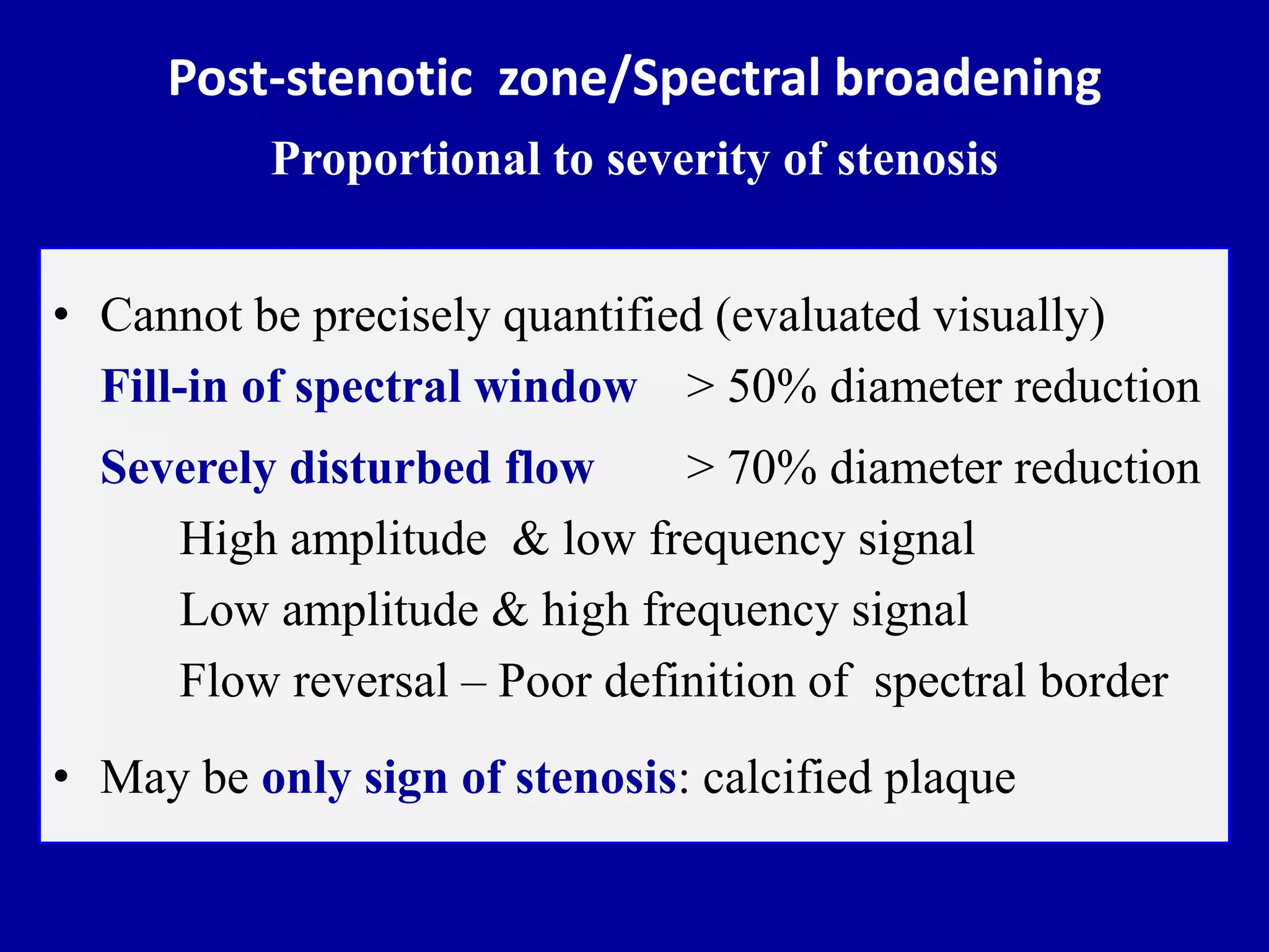
- Changes in flow related to stenosis


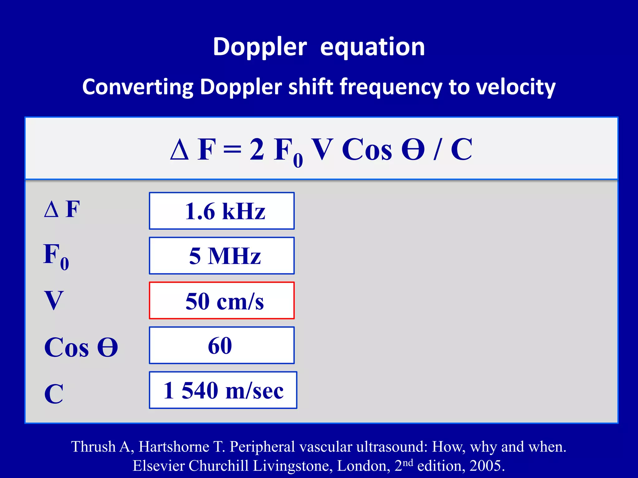


![Doppler principles [2]](https://cdn.slidesharecdn.com/ss_thumbnails/dopplerprinciples2-210517111747-thumbnail.jpg?width=640&height=640&fit=bounds)


![Doppler principles [1]](https://cdn.slidesharecdn.com/ss_thumbnails/dopplerprinciples1-210517111539-thumbnail.jpg?width=640&height=640&fit=bounds)