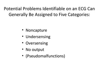
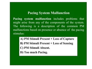
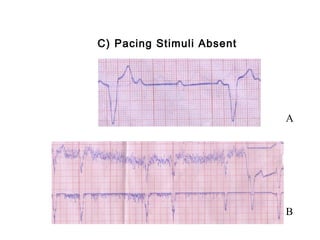
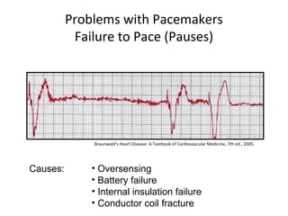
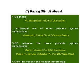
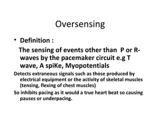
Cardiac Pace-Makers
 
Pacemaker Malfunctions, Part III
Salah Atta, MD
Professor of Cardiology,
Cardiology Department
Potential Problems Identifiable on an ECG Can
Generally Be Assigned to Five Categories:
• Noncapture
• Undersensing
• Oversensing
• No output
• (Pseudomalfunctions)
Pacing System Malfunction
Pacing system malfunction includes problems that
might arise from any of the components of the system.
The following is a description of the common PM
malfunctions based on presence or absence of the pacing
stimulus:
A) PM Stimuli Present + Loss of Capture
B) PM Stimuli Present + Loss of Sensing
C) PM Stimuli Absent.
D) Too much Pacing.
A) Pacing Stimulus Present with Loss of
Capture
Noncapture or loss of capture
1-Diagnosis:
Stimulus + NO subsequent paced P or QRS complex
2-Check spike
3-DD from failure to sense, and the spike is fired but
fall in the physiological refractory period.
4-Consider the cause of loss of capture?
5
Noncapture/Failure to Capture
Pacer’s electrical stimulus (pacing) fails to depolarize 
(capture) the heart. SoPacing is simply unsuccessful 
at stimulating a contraction
ECG shows properly timed pacer spikes but no cardiac 
response
↓ CO occurs
↓ Investigation: X-ray chest , PM check by 
programmer, full lab work.
Problems with Pacemakers
Failure to Capture
Causes: • Threshold rise.
• Lead dislodgement
• Lead fracture
Less Common Causes of Noncapture
May Include:
• Twiddler’s syndrome
• Electrolyte abnormalities e.g.
hyperkalemia
• Myocardial infarction
• Drug therapy
• Battery depletion
• Exit block
B) Pacing Stimulus Present whenever
unexpected
Undersensing
1-Diagnosis of Undersensing:
Spontaneous P or QRS complex, followed by a Stimulus
(which should not have been fired)
2-Check Set Sensitivity.
3-Consider the Cause of Undersensing?
4-Increase Sensitivity Temporarily Till Cause is Treated.
9
Undersensing:  Failure to sense
Pacer fails to detect an intrinsic rhythm
Paces unnecessarily (overpacing)
Patient may feel “extra beats”
If an unneeded pacer spike falls in the latter 
portion of T wave, dangerous 
tachyarrhythmias or V fib may occur (R on 
T).
non-sensed R-waves
Ventricular Undersensing
Causes of Undersensing
Dislodged Lead
Insulation Break
Too low sensitivity
Problem Solving
Program the sensitivity to a lower number
i.e increase the sensitivity.
C) Pacing Stimuli Absent
A
B
Problems with Pacemakers
Failure to Pace (Pauses)
Causes: • Oversensing
• Battery failure
• Internal insulation failure
• Conductor coil fracture
Braunwald's Heart Disease: A Textbook of Cardiovascular Medicine, 7th ed., 2005.
C) Pacing Stimuli Absent
1-Diagnosis:
NO pacing stimuli + NO P or QRS complex
2-Consider one of three possible system
malfunctions:
1-Oversensing, 2-Open Circuit, 3-Defective Battery
3-DD between the three possible system
malfunctions:
Magnet->stimulus->P or QRS=Oversensing
Magnet->no stimulus, or stimulus->No P or QRS=Open Circuit
4-Consider causes and manage accordingly
Oversensing
• Definition :
The sensing of events other than P or R-
waves by the pacemaker circuit e.g T
wave, A spiKe, Myopotentials
Detects extraneous signals such as those produced by
electrical equipment or the activity of skeletal muscles
(tensing, flexing of chest muscles)
So inhibits pacing as it would a true heart beat so causing
pauses or underpacing.
Causes of Oversensing
• Too high sensitivity,
• Insulation Break, Intermittent Lead
Fracture.
• Myopotentials. -EMI.
• Program sensitivity to a higher number
(↓sensitivity).
• Change polarity to bipolar
• Program the refractory period longer
Problem Solving
17
Pacer Failure
A. Early
electrode displacement/breakage
B. Failure > 6 months
Premature battery depletion
Faulty pulse generator
Possible problems with DDD pacing
1. Tracking of a too fast atrial rate may cause
serious ventricular response (e.g in case of
atrial tachycardia, atrial flutter or atrial
fibrillation) if no mode switch and high
upper tracking rate.
2. Pacemaker mediated tachycardia.
3. Ventricular inhibition 2ry to atrial pacing
may cause asystole (Cross talk).
4. Others.
Pacemaker Pseudomalfunctions
• Pacemaker mediated tachycardia:
Pacemaker Mediated Tachycardia
(PMT)
Rapid ventricular pacing due to
RETROGRADE CONDUCTION, sensed by
the PM and responding by V pacing and
so on, most commonly at exactly the
upper rate limit.
Retrograde Conduction
• Propagation of an impulse from the ventricle back
to the atrium, Also known as VA conduction.
• 60 % of the population have the ability to conduct
retrogradely
• 33 % of patients with complete heart block have
the ability to conduct retrogradely
• Average retrograde conduction time= 235ms ± 55
ms
AVD
PVARP PVARP
Retrograde P waves
PVARP PVARP
PVC
Pacemaker Mediated Tachycardia
AVD
PVARP AREPVARP
AVD
PVARP
Retrograde P wavePVC
Prolong PVARP or Atrial Refractory Extension
after a PVC
Pacemaker Mediated Tachycardia
Problem Solving
Crosstalk
• Sensing of the atrial output pulse by the ventricular sense
amplifier
• Inappropriate inhibition of the ventricular pacing due to sensing
of the atrial output pulse by the ventricular sense amplifier.
• Crosstalk is only seen in dual chamber or biventricular
pacemakers. Also called crosstalk inhibition, far-field sensing, or
self-inhibition.
Problems with Pacemakers
Failure to Pace
Causes: • Crosstalk
Braunwald's Heart Disease: A Textbook of Cardiovascular Medicine, 7th ed., 2005.
Management by programming a ventricular blanking period
Factors Affecting Crosstalk
• Atrial pulse amplitude and pulse width
• Ventricular sensitivity
• Anatomical location of atrial and
ventricular electrodes
Managing Crosstalk
• Atrial Pulse Energy
• Ventricular Sensitivity
• Ventricular Blanking Period
Ventricular Blanking Period (VB)
• A short (21-75 ms) period that begins
simultaneously with an atrial output pulse
and during which the ventricular sense
amplifier is totally blind to incoming signals
but it is modifiable only by the
manifacturer.
AV delay
VB
Fusion and Pseudofusion beats
PM behaviour above ULI Pacemaker
Wenckebach
Mode Switching
from DDD to DDI or VVI
Implantable Cardioverter Defibrillator
(ICD)
ICD Implantation
• Secondary prevention: Prevention of SCD in
patients with prior VF or sustained VT.
• Primary prevention: Prevention of SCD in
individuals without a h/o VF or sustained VT.
Indications For ICD
• VF/sustained unstable VT not in the setting of a
completely reversible cause.
• LVEF ≤ 35%, CHF NYHA class II, III.
• Ischemic dilated cardiomyopathy, LVEF ≤ 40%,
NSVT and inducible sustained VT.
• Syncope, LV dysfunction, inducible sustained VT.
• High risk patients with: hypertrophic
cardiomyopathy, LQT syndrome, RV dysplasia,
Brugada syndrome
• Impedance measurementImpedance measurement : 300 - 1000: 300 - 1000
ohms.... calculated / displayedohms.... calculated / displayed
• SVC coil , RV coil impedence: 30-100 VSVC coil , RV coil impedence: 30-100 V
• Sensing threshold (localy sensed intrinsicSensing threshold (localy sensed intrinsic
electrogram)electrogram)
• Amplitude (Minimum : “P” - 2mV , “R” - 5mV)Amplitude (Minimum : “P” - 2mV , “R” - 5mV)
• Pacing thresholdPacing threshold
• (Measured amplitude at 0.5 ms.)(Measured amplitude at 0.5 ms.)
• Paced rate > = 20 ppm above spontaneous ratePaced rate > = 20 ppm above spontaneous rate
• Decrement variable output : Threshold < 1-1.5V @ 0.5ms.Decrement variable output : Threshold < 1-1.5V @ 0.5ms.
ICD ImplantationImplantation MeasurementsMeasurements
Dual Chamber ICD
Ellenbogen K A, 2007Ellenbogen K A, 2007
38
Shock
ICD interrogation revealed the
following:
One shock was delivered, as above, with 9 other aborted
shocks for long non-sustained VT (asymptomatic).
CRT Indications
• Age > 18 years, Sinus rhythm, EF less than 35%, NYHA class III-
IV heart failure despite optimal medical treatment for at least
3 months.
• Indicator of dyssynchrony either:
Standard electrical criteria in the form of Wide QRS complex
≥130 ms, left bundle branch block (LBBB) with echo evidence
of dyssynchrony in group 1 (or)
ECG of a wide QRS complex case
Before CRT implantation
LV lead position
After CRT implantation
Echo appearance before and 24 hours
after CRT
FMR Before CRT
implantation
24 hours after CRT implantation
Example 1
Atrial sensed, ventricular paced
Consistent with DDD or VDD pacing in VAT mode
The Alan E. Lindsay ECG Learning Center ; http://medstat.med.utah.edu/kw/ecg/
Example 2
Atrial paced
Consistent with AAI or DDD
The Alan E. Lindsay ECG Learning Center ; http://medstat.med.utah.edu/kw/ecg/
Example 3
Failure to Pace
The Alan E. Lindsay ECG Learning Center ; http://medstat.med.utah.edu/kw/ecg/
Example 4
Failure to Sense
The Alan E. Lindsay ECG Learning Center ; http://medstat.med.utah.edu/kw/ecg/
Thank you

Cardiac pacemakerspart iii

Editor's Notes

  • #3 The causes of undersensing, oversensing, noncapture, lack of output, and pseudomalfunctions vary. However, each of these anomalies compromises the pacemaker’s ability to supplement intrinsic conduction.
  • #8 Twiddler’s syndrome can be identified radiographically. Hyperkalemia, an electrolyte abnormality, is defined by a high serum potassium level and is commonly caused by kidney disease. Hyperkalemia may affect the stimulation threshold. If a myocardial infarction occurs near the tip of the lead, an increase in the stimulation threshold and/or noncapture may occur. Drug therapy may affect capture thresholds and result in significant changes from the patient’s baseline. If the delivered voltage is significantly reduced, advanced stages of battery depletion may result in noncapture. Exit block occurs when the stimulation threshold exceeds the pacemaker’s maximum output.