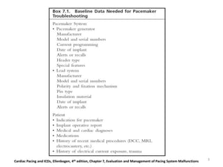
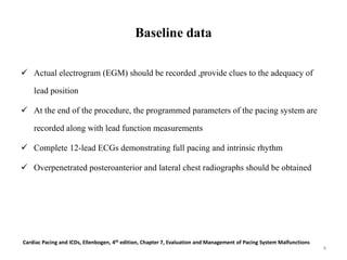
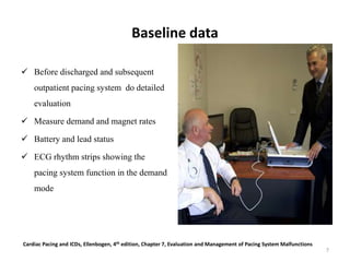
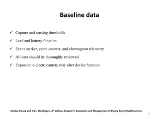
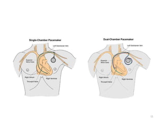
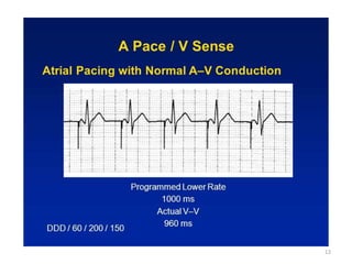
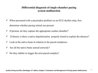
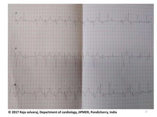
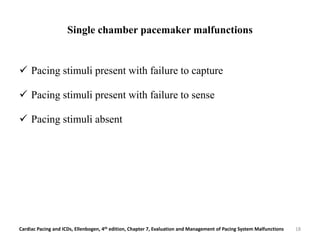
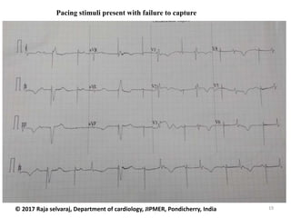
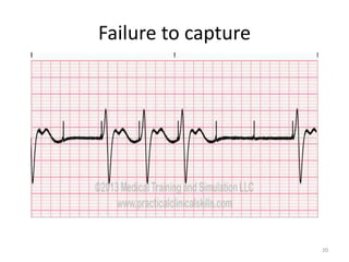
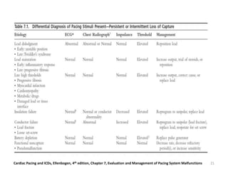
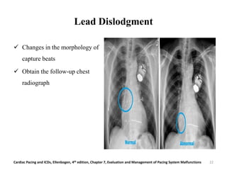
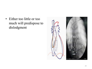
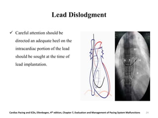
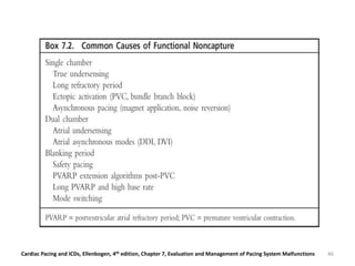
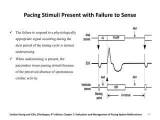
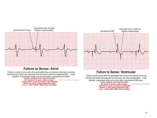
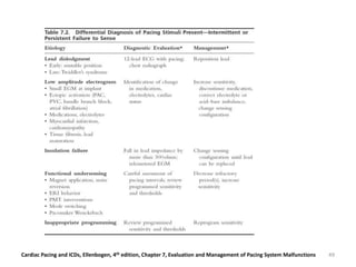
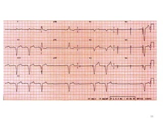
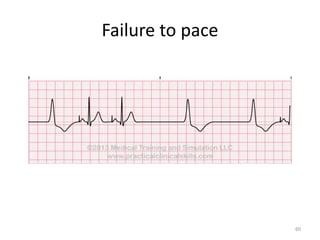
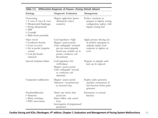
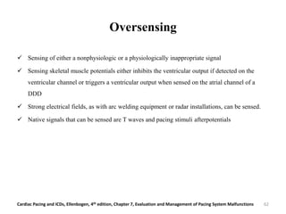
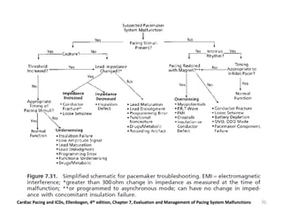
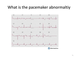
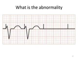
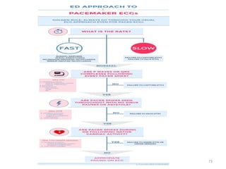
Evaluation and management of
Pacemaker malfunction
Presenter
Dr Praveen Gupta
Department of Pediatric cardiology
AMRITA Hospital
KOCHI (Kerala)
1
Pacing system
 Pacing system malfunction
 consideration of all the components of
system
 Focusing purely on the pulse generator
overlook the true cause of the problem.
 Malfunctions of pulse generators least
frequent
 Unique behavioral eccentricities.
Cardiac Pacing and ICDs, Ellenbogen, 4th edition, Chapter 7, Evaluation and Management of Pacing System Malfunctions
2
Cardiac Pacing and ICDs, Ellenbogen, 4th edition, Chapter 7, Evaluation and Management of Pacing System Malfunctions 3
Baseline data
 Actual electrogram (EGM) should be recorded ,provide clues to the adequacy of
lead position
 At the end of the procedure, the programmed parameters of the pacing system are
recorded along with lead function measurements
 Complete 12-lead ECGs demonstrating full pacing and intrinsic rhythm
 Overpenetrated posteroanterior and lateral chest radiographs should be obtained
Cardiac Pacing and ICDs, Ellenbogen, 4th edition, Chapter 7, Evaluation and Management of Pacing System Malfunctions
4
5
6
Baseline data
 Before discharged and subsequent
outpatient pacing system do detailed
evaluation
 Measure demand and magnet rates
 Battery and lead status
 ECG rhythm strips showing the
pacing system function in the demand
mode
Cardiac Pacing and ICDs, Ellenbogen, 4th edition, Chapter 7, Evaluation and Management of Pacing System Malfunctions
7
Baseline data
 Capture and sensing thresholds
 Lead and battery function
 Event marker, event counter, and electrogram telemetry
 All data should be thoroughly reviewed
 Exposure to electrocautery may alter device function
Cardiac Pacing and ICDs, Ellenbogen, 4th edition, Chapter 7, Evaluation and Management of Pacing System Malfunctions
8
Baseline data
 Intermittent pacing system malfunction obtain sufficient ECG documentation
 Retrieve these tracings from referring physicians’ offices, medical records
 Pacemaker malfunctions” are often misinterpretations of normal pacemaker
function by persons unfamiliar with pacemaker follow-up evaluations
Cardiac Pacing and ICDs, Ellenbogen, 4th edition, Chapter 7, Evaluation and Management of Pacing System Malfunctions
9
10
11
12
13
14
Differential diagnosis of single-chamber pacing
system malfunction
 When presented with a pacemaker problem on an ECG rhythm strip, first
determine whether pacing stimuli are present
 If present, do they capture the appropriate cardiac chamber?
 If absent, is there a native depolarization properly timed to explain the absence?
 Look at the native beats in relation to the paced complexes
 Are all the native beats sensed correctly?
 Do they inhibit or trigger the next paced complex?
Cardiac Pacing and ICDs, Ellenbogen, 4th edition, Chapter 7, Evaluation and Management of Pacing System Malfunctions 15
16© 2017 Raja selvaraj, Department of cardiology, JIPMER, Pondicherry, India
17© 2017 Raja selvaraj, Department of cardiology, JIPMER, Pondicherry, India
Single chamber pacemaker malfunctions
 Pacing stimuli present with failure to capture
 Pacing stimuli present with failure to sense
 Pacing stimuli absent
Cardiac Pacing and ICDs, Ellenbogen, 4th edition, Chapter 7, Evaluation and Management of Pacing System Malfunctions 18
19
Pacing stimuli present with failure to capture
© 2017 Raja selvaraj, Department of cardiology, JIPMER, Pondicherry, India
Failure to capture
20
Cardiac Pacing and ICDs, Ellenbogen, 4th edition, Chapter 7, Evaluation and Management of Pacing System Malfunctions 21
Lead Dislodgment
 Changes in the morphology of
capture beats
 Obtain the follow-up chest
radiograph
Cardiac Pacing and ICDs, Ellenbogen, 4th edition, Chapter 7, Evaluation and Management of Pacing System Malfunctions 22
• Either too little or too
much will predispose to
dislodgment
23
Lead Dislodgment
 Careful attention should be
directed an adequate heel on the
intracardiac portion of the lead
should be sought at the time of
lead implantation.
Cardiac Pacing and ICDs, Ellenbogen, 4th edition, Chapter 7, Evaluation and Management of Pacing System Malfunctions 24
Lead Dislodgment
 Review the recorded electrograms from the initial implant
 Looking for a 2 to 3mV current of injury pattern (“STsegment” elevation)
 Absence of degree of current of injury, increased lead dislodgment
 Anchoring sleeve for adequate fixation at the time of reoperation
 Correction requires reposition the lead
Cardiac Pacing and ICDs, Ellenbogen, 4th edition, Chapter 7, Evaluation and Management of Pacing System Malfunctions 25
Lead Dislodgment
 Twiddler’s syndrome, the most
common cause of a late lead
dislodgment.
 If damage to the conductor coil or
insulation is noted, the lead
should not be reused.
Cardiac Pacing and ICDs, Ellenbogen, 4th edition, Chapter 7, Evaluation and Management of Pacing System Malfunctions 26
27Cardiac Pacing and ICDs, Ellenbogen, 4th edition, Chapter 6, Pacemaker timing cycle
28Cardiac Pacing and ICDs, Ellenbogen, 4th edition, Chapter 6, Pacemaker timing cycle
29Cardiac Pacing and ICDs, Ellenbogen, 4th edition, Chapter 6, Pacemaker timing cycle
30Cardiac Pacing and ICDs, Ellenbogen, 4th edition, Chapter 6, Pacemaker timing cycle
31Cardiac Pacing and ICDs, Ellenbogen, 4th edition, Chapter 6, Pacemaker timing cycle
32Cardiac Pacing and ICDs, Ellenbogen, 4th edition, Chapter 6, Pacemaker timing cycle
33Cardiac Pacing and ICDs, Ellenbogen, 4th edition, Chapter 6, Pacemaker timing cycle
34
Response of pacemakers to magnet placement. In general, magnet application results in asynchronous pacing in all pacemakers with manufacturer-specific exceptions explained in the figure. The
first step shows the different magnet response modes programmable in pacemakers and the corresponding electrocardiogram (ECG) responses (Each mode has been explained in detail in the
text). If no ECG response is seen on magnet application, the pacemaker might have been programmed to ignore the magnet or might have a depleted battery or one of the different modes shown
in the flowchart. Asynchronous pacing occurs at a fixed magnet rate according to the device manufacturer, individual models, and remaining battery life. Pacemaker programmed to DDD pace as
DOO, VVI as VOO, and AAI as AOO. On magnet removal, all pacemakers revert to the original programmed pacing mode, except for Sorin pacemakers that undergo a ‘capture test’ with six pacing
outputs at the magnet rate and 94 ms AV delay and then a ‘rate test’ with two paced outputs at a basic programmed rate and rest AV delay followed by pacing at a preprogrammed rate. Battery
statuses: BOL, beginning of life; ERI, elective replacement indicator; ERT, elective replacement time; ERN, elective replacement near; EOL, end of life. The magnet rates at different battery status
have been specified for each device manufacturer. At EOL and below, the response of pacemakers to magnet placement is unpredictable across all the manufacturers. bpm, beats per minute; AV,
atrioventricular, Asynch, asynchronous; Sync; synchronous; †TMT, Threshold Margin Test; PW, pulse width.
Clinical applications of magnets on cardiac rhythm management devices Sony Jacob1*, Sidakpal S. Panaich1, Rahul Maheshwari 2, John W. Haddad3, Benzy J. Padanilam4, and Sinoj K.
John5
High Thresholds; Lead Maturation
 Pressure of the lead-electrode system
induce an inflammatory reaction at the
electrode-myocardial interface.
 Electrode displaced from myocardium
 Increases the capture threshold.
 With time, inflammatory reaction
subsides, capture and sensing thresholds
improve
Cardiac Pacing and ICDs, Ellenbogen, 4th edition, Chapter 7, Evaluation and Management of Pacing System Malfunctions 35
Acute management
 Increasing the output of the pacemaker
 If not feasible, one needs to determine the status of the native underlying rhythm.
 If it is stable wait for the threshold to fall
 If underlying rhythm is not stable, insert a temporary pacemaker lead and consider
an urgent intervention to reposition or replace the lead
Cardiac Pacing and ICDs, Ellenbogen, 4th edition, Chapter 7, Evaluation and Management of Pacing System Malfunctions 36
High Thresholds in chronic lead
 Evaluate transient etiologies
 Hyperkalemia and acidemia
 Flecainide
 Myocardial fibrosis
 Myocardial infarction
Cardiac Pacing and ICDs, Ellenbogen, 4th edition, Chapter 7, Evaluation and Management of Pacing System Malfunctions 37
High Thresholds in chronic lead
 If a transient cause is identified and it can be corrected, the problem can be
managed with a transient increase in output or by use of temporary pacing
 If the output programmability of the device is not sufficient to overcome these
causes, placement of a new lead will be required.
 Given that the lead is not infected, explantation is not mandatory
Cardiac Pacing and ICDs, Ellenbogen, 4th edition, Chapter 7, Evaluation and Management of Pacing System Malfunctions 38
Lead Insulation Defects
 Due to extrinsic forces applied to the lead
 Suture sleeve
 Medial subclavicular musculotendinous complex
 Abrasion of the external insulation
39
Lead Insulation Defects
 Extracardiac muscle stimulation
 Amplitude of the pacing stimulus
 chest radiograph may reveal a problem
 One might see a deformity of the conductor coil
Cardiac Pacing and ICDs, Ellenbogen, 4th edition, Chapter 7, Evaluation and Management of Pacing System Malfunctions 40
Open Circuit (Conductor fracture)
 With a total open circuit, no energy will
traverse the gap between the two portions
of thelead and there will be an absence of
pacing artifacts on the ECG and loss of
capture.
 If the two ends of the conductor are
making any contact at all, the resistance to
current flow will be increased to attenuate
the amount of current and energy reaching
the heart, but a stimulus will be present.
Cardiac Pacing and ICDs, Ellenbogen, 4th edition, Chapter 7, Evaluation and Management of Pacing System Malfunctions 41
Open Circuit
42Cardiac Pacing and ICDs, Ellenbogen, 4th edition, Chapter 7, Evaluation and Management of Pacing System Malfunctions
Chest radiograph demonstrating displacement of the terminal pin out of the head of a pacemaker
open circuit
 Lead impedance increase
 If concomitant break in insulation, the
impedance may be normal or only
minimally elevated
 A radiograph may show the conductor
fracture, particularly with unipolar leads.
Cardiac Pacing and ICDs, Ellenbogen, 4th edition, Chapter 7, Evaluation and Management of Pacing System Malfunctions 43
Functional Noncapture
 When a pacing stimulus occurs in the physiologic refractory period of a native depolarization,
it will not capture
 This may be due to a primary problem of failure to sense or to functional undersensing.
 Functional undersensing is associated with the basic timing design of the system as with too
long a refractory period.
Cardiac Pacing and ICDs, Ellenbogen, 4th edition, Chapter 7, Evaluation and Management of Pacing System Malfunctions 44
Functional Noncapture
 It was particularly common in the committed AV sequential (DVI) pacing systems
 The atrial stimulus occurs in the refractory period of the native atrial depolarization that
conducted to the ventricle
 Ventricular output coincide with the refractory period of the ventricular depolarization.
Cardiac Pacing and ICDs, Ellenbogen, 4th edition, Chapter 7, Evaluation and Management of Pacing System Malfunctions 45
Cardiac Pacing and ICDs, Ellenbogen, 4th edition, Chapter 7, Evaluation and Management of Pacing System Malfunctions 46
Pacing Stimuli Present with Failure to Sense
 The failure to respond to a physiologically
appropriate signal occurring during the
alert period of the timing cycle is termed
undersensing
 When undersensing is present, the
pacemaker issues pacing stimuli because
of the perceived absence of spontaneous
cardiac activity
47Cardiac Pacing and ICDs, Ellenbogen, 4th edition, Chapter 7, Evaluation and Management of Pacing System Malfunctions
48
Cardiac Pacing and ICDs, Ellenbogen, 4th edition, Chapter 7, Evaluation and Management of Pacing System Malfunctions 49
Low amplitude electogram
 One cause of undersensing is that of inadequate signal amplitude at the time of initial implant.
 This may result if the patient has no intrinsic rhythm to measure at implant (i.e., temporary
ventricular pacing or, on the atrial channel, atrial fibrillation)
Cardiac Pacing and ICDs, Ellenbogen, 4th edition, Chapter 7, Evaluation and Management of Pacing System Malfunctions 50
Change in Native Signal
 Myocardial infarction
 Primary myopathic process
 Bundle branch block.
 Hyperkalemia
 Pharmacologic therapy, particularly the antiarrhythmic agents
Cardiac Pacing and ICDs, Ellenbogen, 4th edition, Chapter 7, Evaluation and Management of Pacing System Malfunctions 51
Change in Native Signal
 Inappropriate Programmed Sensitivity
 When an undersensing problem is encountered, the sensitivity should be increased or set to a
higher sensitivity so that the system will recognize and respond to smaller amplitude signals
Cardiac Pacing and ICDs, Ellenbogen, 4th edition, Chapter 7, Evaluation and Management of Pacing System Malfunctions 52
Lead Insulation Failure
 Decrease impedance
 Increase in battery current drain
 Increase in capture threshold
 Change in pulse artifact amplitude
 Extracardiac muscle stimulation.
 Increase the sensitivity of the system
 Definitive correction will require repair or replacement of the lead
Cardiac Pacing and ICDs, Ellenbogen, 4th edition, Chapter 7, Evaluation and Management of Pacing System Malfunctions 53
Lead Dislodgment
 Frequently accompanied by undersensing
 Electrode may no longer be in contact with the myocardium,
 Incoming signal will be different from and usually smaller than that recorded at
implant, resulting in sensing failure
 Correction requires repositioning the dislodged lead
 Increasing the sensitivity restore normal sensing function until lead repositioned
Cardiac Pacing and ICDs, Ellenbogen, 4th edition, Chapter 7, Evaluation and Management of Pacing System Malfunctions 54
Lead Maturation
 Inflammatory reaction that occurs at the electrodemyocardial interface
 Physically separates the electrode from active functional myocardium
 Will attenuate the amplitude of the signal (20% to 40%)
 Major reason for sensing failure
 Increasing the sensitivity of the pacemaker
 Initiating measure for lead maturation
Cardiac Pacing and ICDs, Ellenbogen, 4th edition, Chapter 7, Evaluation and Management of Pacing System Malfunctions 55
Functional Under sensing
 Failure to sense an appropriate physiologic signal
 Occurs due to native beats falling within the refractory period after a paced or sensed beat,
 Fusion and pseudofusion beats are normal phenomenon
 Most common cause ,magnet is placed over the pacemaker and induces asynchronous pacing.
 If too many signals are sensed by the pacemaker in a very short time electromagnetic
interference (EMI) or “noise.”
 EMI Inhibiting the pacemaker when the patient might be asystolic, the pacemaker reverts to
asynchronous function, termed noise mode operation
Cardiac Pacing and ICDs, Ellenbogen, 4th edition, Chapter 7, Evaluation and Management of Pacing System Malfunctions 56
Cardiac Pacing and ICDs, Ellenbogen, 4th edition, Chapter 7, Evaluation and Management of Pacing System Malfunctions 57
Pacing Stimuli Absent with Failure to Capture
 Major category of pacing system malfunction
 Record multiple leads simultaneously or sequentially.
 Indication for using a digital ECG machine
Cardiac Pacing and ICDs, Ellenbogen, 4th edition, Chapter 7, Evaluation and Management of Pacing System Malfunctions 58
59
Failure to pace
60
Cardiac Pacing and ICDs, Ellenbogen, 4th edition, Chapter 7, Evaluation and Management of Pacing System Malfunctions 61
Oversensing
 Sensing of either a nonphysiologic or a physiologically inappropriate signal
 Sensing skeletal muscle potentials either inhibits the ventricular output if detected on the
ventricular channel or triggers a ventricular output when sensed on the atrial channel of a
DDD
 Strong electrical fields, as with arc welding equipment or radar installations, can be sensed.
 Native signals that can be sensed are T waves and pacing stimuli afterpotentials
Cardiac Pacing and ICDs, Ellenbogen, 4th edition, Chapter 7, Evaluation and Management of Pacing System Malfunctions 62
Oversensing
 Reducing the sensitivity is usually effective management
 Is recommended only if the native signal for which sensing is desired is sufficiently large to
allow it to continue to be appropriately sensed.
 If reducing the sensitivity will result in undersensing of appropriate signals, one might
program the pacemaker to the triggered mode
 Definitive management requires lead replacement.
Cardiac Pacing and ICDs, Ellenbogen, 4th edition, Chapter 7, Evaluation and Management of Pacing System Malfunctions 63
Oversensing
 Differentiate oversensing from the other causes by applying a magnet to the pacemaker
 The magnet will cause the pacemaker to revert to asynchronous function
 If the pauses are eliminated, the problem is that of oversensing
 To determine the source of the oversensing, it is sometimes necessary to record the surface
ECG while the patient is in the environment in which the reported symptoms occur.
 It may be necessary to have the patient perform provocative maneuvers as were described
earlier in the section on lead evaluation.
Cardiac Pacing and ICDs, Ellenbogen, 4th edition, Chapter 7, Evaluation and Management of Pacing System Malfunctions 64
Oversensing
 Upper extremity isometric exercises
 Tensing the pectoral muscles
 Do sit ups to tighten the abdominal muscles in the case of an abdominal implant
 Very deep breaths if diaphragmatic oversensing is suspected
 These maneuvers should be performed while continuously monitoring the rhythm and, if
available, in conjunction with telemetered event markers and electrograms
Cardiac Pacing and ICDs, Ellenbogen, 4th edition, Chapter 7, Evaluation and Management of Pacing System Malfunctions 65
Open Circuit
 Event marker telemetry will indicate that the pacemaker released a pulse
 A simultaneously recorded ECG will be necessary to demonstrate that this output pulse never
reached the heart, as no stimulus artifact is recorded
 High impedance
Cardiac Pacing and ICDs, Ellenbogen, 4th edition, Chapter 7, Evaluation and Management of Pacing System Malfunctions 66
Open Circuit
 No current drain associated with the programmed output
 Application of a magnet to the pacemaker will not restore pacing
 Most common is a conductor fracture, failure to tighten the set-screw adequately
 Result from incompatibility between the lead pin and the header connector of the pacemaker
Cardiac Pacing and ICDs, Ellenbogen, 4th edition, Chapter 7, Evaluation and Management of Pacing System Malfunctions 67
Dual-chamber pacing system malfunction
 Five major classes of dual-chamber pacing system malfunction.
 First class includes all the abnormalities as with single-chamber pacing
 The second class occur only with a dual-chamber system, such as crosstalk and
endless-loop tachycardia (ELT).
Cardiac Pacing and ICDs, Ellenbogen, 4th edition, Chapter 7, Evaluation and Management of Pacing System Malfunctions 68
Dual-chamber pacing system malfunction
 The third problems occurs when the rate response sensor responds to a
physiologically inappropriate signal, which in turn drives the pacemaker.
 Fourth problems is primarily due to a lack of understanding of the system
 Fifth group, mismatch between the programmed parameters and patient’s
physiology
Cardiac Pacing and ICDs, Ellenbogen, 4th edition, Chapter 7, Evaluation and Management of Pacing System Malfunctions 69
Cardiac Pacing and ICDs, Ellenbogen, 4th edition, Chapter 7, Evaluation and Management of Pacing System Malfunctions 70
What is the pacemaker abnormaltiy
71
What is the abnormality
72
73
Thank you
74

Evaluation and management of Pacemaker malfunction

  • 1.
    Evaluation and managementof Pacemaker malfunction Presenter Dr Praveen Gupta Department of Pediatric cardiology AMRITA Hospital KOCHI (Kerala) 1
  • 2.
    Pacing system  Pacingsystem malfunction  consideration of all the components of system  Focusing purely on the pulse generator overlook the true cause of the problem.  Malfunctions of pulse generators least frequent  Unique behavioral eccentricities. Cardiac Pacing and ICDs, Ellenbogen, 4th edition, Chapter 7, Evaluation and Management of Pacing System Malfunctions 2
  • 3.
    Cardiac Pacing andICDs, Ellenbogen, 4th edition, Chapter 7, Evaluation and Management of Pacing System Malfunctions 3
  • 4.
    Baseline data  Actualelectrogram (EGM) should be recorded ,provide clues to the adequacy of lead position  At the end of the procedure, the programmed parameters of the pacing system are recorded along with lead function measurements  Complete 12-lead ECGs demonstrating full pacing and intrinsic rhythm  Overpenetrated posteroanterior and lateral chest radiographs should be obtained Cardiac Pacing and ICDs, Ellenbogen, 4th edition, Chapter 7, Evaluation and Management of Pacing System Malfunctions 4
  • 5.
  • 6.
  • 7.
    Baseline data  Beforedischarged and subsequent outpatient pacing system do detailed evaluation  Measure demand and magnet rates  Battery and lead status  ECG rhythm strips showing the pacing system function in the demand mode Cardiac Pacing and ICDs, Ellenbogen, 4th edition, Chapter 7, Evaluation and Management of Pacing System Malfunctions 7
  • 8.
    Baseline data  Captureand sensing thresholds  Lead and battery function  Event marker, event counter, and electrogram telemetry  All data should be thoroughly reviewed  Exposure to electrocautery may alter device function Cardiac Pacing and ICDs, Ellenbogen, 4th edition, Chapter 7, Evaluation and Management of Pacing System Malfunctions 8
  • 9.
    Baseline data  Intermittentpacing system malfunction obtain sufficient ECG documentation  Retrieve these tracings from referring physicians’ offices, medical records  Pacemaker malfunctions” are often misinterpretations of normal pacemaker function by persons unfamiliar with pacemaker follow-up evaluations Cardiac Pacing and ICDs, Ellenbogen, 4th edition, Chapter 7, Evaluation and Management of Pacing System Malfunctions 9
  • 10.
  • 11.
  • 12.
  • 13.
  • 14.
  • 15.
    Differential diagnosis ofsingle-chamber pacing system malfunction  When presented with a pacemaker problem on an ECG rhythm strip, first determine whether pacing stimuli are present  If present, do they capture the appropriate cardiac chamber?  If absent, is there a native depolarization properly timed to explain the absence?  Look at the native beats in relation to the paced complexes  Are all the native beats sensed correctly?  Do they inhibit or trigger the next paced complex? Cardiac Pacing and ICDs, Ellenbogen, 4th edition, Chapter 7, Evaluation and Management of Pacing System Malfunctions 15
  • 16.
    16© 2017 Rajaselvaraj, Department of cardiology, JIPMER, Pondicherry, India
  • 17.
    17© 2017 Rajaselvaraj, Department of cardiology, JIPMER, Pondicherry, India
  • 18.
    Single chamber pacemakermalfunctions  Pacing stimuli present with failure to capture  Pacing stimuli present with failure to sense  Pacing stimuli absent Cardiac Pacing and ICDs, Ellenbogen, 4th edition, Chapter 7, Evaluation and Management of Pacing System Malfunctions 18
  • 19.
    19 Pacing stimuli presentwith failure to capture © 2017 Raja selvaraj, Department of cardiology, JIPMER, Pondicherry, India
  • 20.
  • 21.
    Cardiac Pacing andICDs, Ellenbogen, 4th edition, Chapter 7, Evaluation and Management of Pacing System Malfunctions 21
  • 22.
    Lead Dislodgment  Changesin the morphology of capture beats  Obtain the follow-up chest radiograph Cardiac Pacing and ICDs, Ellenbogen, 4th edition, Chapter 7, Evaluation and Management of Pacing System Malfunctions 22
  • 23.
    • Either toolittle or too much will predispose to dislodgment 23
  • 24.
    Lead Dislodgment  Carefulattention should be directed an adequate heel on the intracardiac portion of the lead should be sought at the time of lead implantation. Cardiac Pacing and ICDs, Ellenbogen, 4th edition, Chapter 7, Evaluation and Management of Pacing System Malfunctions 24
  • 25.
    Lead Dislodgment  Reviewthe recorded electrograms from the initial implant  Looking for a 2 to 3mV current of injury pattern (“STsegment” elevation)  Absence of degree of current of injury, increased lead dislodgment  Anchoring sleeve for adequate fixation at the time of reoperation  Correction requires reposition the lead Cardiac Pacing and ICDs, Ellenbogen, 4th edition, Chapter 7, Evaluation and Management of Pacing System Malfunctions 25
  • 26.
    Lead Dislodgment  Twiddler’ssyndrome, the most common cause of a late lead dislodgment.  If damage to the conductor coil or insulation is noted, the lead should not be reused. Cardiac Pacing and ICDs, Ellenbogen, 4th edition, Chapter 7, Evaluation and Management of Pacing System Malfunctions 26
  • 27.
    27Cardiac Pacing andICDs, Ellenbogen, 4th edition, Chapter 6, Pacemaker timing cycle
  • 28.
    28Cardiac Pacing andICDs, Ellenbogen, 4th edition, Chapter 6, Pacemaker timing cycle
  • 29.
    29Cardiac Pacing andICDs, Ellenbogen, 4th edition, Chapter 6, Pacemaker timing cycle
  • 30.
    30Cardiac Pacing andICDs, Ellenbogen, 4th edition, Chapter 6, Pacemaker timing cycle
  • 31.
    31Cardiac Pacing andICDs, Ellenbogen, 4th edition, Chapter 6, Pacemaker timing cycle
  • 32.
    32Cardiac Pacing andICDs, Ellenbogen, 4th edition, Chapter 6, Pacemaker timing cycle
  • 33.
    33Cardiac Pacing andICDs, Ellenbogen, 4th edition, Chapter 6, Pacemaker timing cycle
  • 34.
    34 Response of pacemakersto magnet placement. In general, magnet application results in asynchronous pacing in all pacemakers with manufacturer-specific exceptions explained in the figure. The first step shows the different magnet response modes programmable in pacemakers and the corresponding electrocardiogram (ECG) responses (Each mode has been explained in detail in the text). If no ECG response is seen on magnet application, the pacemaker might have been programmed to ignore the magnet or might have a depleted battery or one of the different modes shown in the flowchart. Asynchronous pacing occurs at a fixed magnet rate according to the device manufacturer, individual models, and remaining battery life. Pacemaker programmed to DDD pace as DOO, VVI as VOO, and AAI as AOO. On magnet removal, all pacemakers revert to the original programmed pacing mode, except for Sorin pacemakers that undergo a ‘capture test’ with six pacing outputs at the magnet rate and 94 ms AV delay and then a ‘rate test’ with two paced outputs at a basic programmed rate and rest AV delay followed by pacing at a preprogrammed rate. Battery statuses: BOL, beginning of life; ERI, elective replacement indicator; ERT, elective replacement time; ERN, elective replacement near; EOL, end of life. The magnet rates at different battery status have been specified for each device manufacturer. At EOL and below, the response of pacemakers to magnet placement is unpredictable across all the manufacturers. bpm, beats per minute; AV, atrioventricular, Asynch, asynchronous; Sync; synchronous; †TMT, Threshold Margin Test; PW, pulse width. Clinical applications of magnets on cardiac rhythm management devices Sony Jacob1*, Sidakpal S. Panaich1, Rahul Maheshwari 2, John W. Haddad3, Benzy J. Padanilam4, and Sinoj K. John5
  • 35.
    High Thresholds; LeadMaturation  Pressure of the lead-electrode system induce an inflammatory reaction at the electrode-myocardial interface.  Electrode displaced from myocardium  Increases the capture threshold.  With time, inflammatory reaction subsides, capture and sensing thresholds improve Cardiac Pacing and ICDs, Ellenbogen, 4th edition, Chapter 7, Evaluation and Management of Pacing System Malfunctions 35
  • 36.
    Acute management  Increasingthe output of the pacemaker  If not feasible, one needs to determine the status of the native underlying rhythm.  If it is stable wait for the threshold to fall  If underlying rhythm is not stable, insert a temporary pacemaker lead and consider an urgent intervention to reposition or replace the lead Cardiac Pacing and ICDs, Ellenbogen, 4th edition, Chapter 7, Evaluation and Management of Pacing System Malfunctions 36
  • 37.
    High Thresholds inchronic lead  Evaluate transient etiologies  Hyperkalemia and acidemia  Flecainide  Myocardial fibrosis  Myocardial infarction Cardiac Pacing and ICDs, Ellenbogen, 4th edition, Chapter 7, Evaluation and Management of Pacing System Malfunctions 37
  • 38.
    High Thresholds inchronic lead  If a transient cause is identified and it can be corrected, the problem can be managed with a transient increase in output or by use of temporary pacing  If the output programmability of the device is not sufficient to overcome these causes, placement of a new lead will be required.  Given that the lead is not infected, explantation is not mandatory Cardiac Pacing and ICDs, Ellenbogen, 4th edition, Chapter 7, Evaluation and Management of Pacing System Malfunctions 38
  • 39.
    Lead Insulation Defects Due to extrinsic forces applied to the lead  Suture sleeve  Medial subclavicular musculotendinous complex  Abrasion of the external insulation 39
  • 40.
    Lead Insulation Defects Extracardiac muscle stimulation  Amplitude of the pacing stimulus  chest radiograph may reveal a problem  One might see a deformity of the conductor coil Cardiac Pacing and ICDs, Ellenbogen, 4th edition, Chapter 7, Evaluation and Management of Pacing System Malfunctions 40
  • 41.
    Open Circuit (Conductorfracture)  With a total open circuit, no energy will traverse the gap between the two portions of thelead and there will be an absence of pacing artifacts on the ECG and loss of capture.  If the two ends of the conductor are making any contact at all, the resistance to current flow will be increased to attenuate the amount of current and energy reaching the heart, but a stimulus will be present. Cardiac Pacing and ICDs, Ellenbogen, 4th edition, Chapter 7, Evaluation and Management of Pacing System Malfunctions 41
  • 42.
    Open Circuit 42Cardiac Pacingand ICDs, Ellenbogen, 4th edition, Chapter 7, Evaluation and Management of Pacing System Malfunctions Chest radiograph demonstrating displacement of the terminal pin out of the head of a pacemaker
  • 43.
    open circuit  Leadimpedance increase  If concomitant break in insulation, the impedance may be normal or only minimally elevated  A radiograph may show the conductor fracture, particularly with unipolar leads. Cardiac Pacing and ICDs, Ellenbogen, 4th edition, Chapter 7, Evaluation and Management of Pacing System Malfunctions 43
  • 44.
    Functional Noncapture  Whena pacing stimulus occurs in the physiologic refractory period of a native depolarization, it will not capture  This may be due to a primary problem of failure to sense or to functional undersensing.  Functional undersensing is associated with the basic timing design of the system as with too long a refractory period. Cardiac Pacing and ICDs, Ellenbogen, 4th edition, Chapter 7, Evaluation and Management of Pacing System Malfunctions 44
  • 45.
    Functional Noncapture  Itwas particularly common in the committed AV sequential (DVI) pacing systems  The atrial stimulus occurs in the refractory period of the native atrial depolarization that conducted to the ventricle  Ventricular output coincide with the refractory period of the ventricular depolarization. Cardiac Pacing and ICDs, Ellenbogen, 4th edition, Chapter 7, Evaluation and Management of Pacing System Malfunctions 45
  • 46.
    Cardiac Pacing andICDs, Ellenbogen, 4th edition, Chapter 7, Evaluation and Management of Pacing System Malfunctions 46
  • 47.
    Pacing Stimuli Presentwith Failure to Sense  The failure to respond to a physiologically appropriate signal occurring during the alert period of the timing cycle is termed undersensing  When undersensing is present, the pacemaker issues pacing stimuli because of the perceived absence of spontaneous cardiac activity 47Cardiac Pacing and ICDs, Ellenbogen, 4th edition, Chapter 7, Evaluation and Management of Pacing System Malfunctions
  • 48.
  • 49.
    Cardiac Pacing andICDs, Ellenbogen, 4th edition, Chapter 7, Evaluation and Management of Pacing System Malfunctions 49
  • 50.
    Low amplitude electogram One cause of undersensing is that of inadequate signal amplitude at the time of initial implant.  This may result if the patient has no intrinsic rhythm to measure at implant (i.e., temporary ventricular pacing or, on the atrial channel, atrial fibrillation) Cardiac Pacing and ICDs, Ellenbogen, 4th edition, Chapter 7, Evaluation and Management of Pacing System Malfunctions 50
  • 51.
    Change in NativeSignal  Myocardial infarction  Primary myopathic process  Bundle branch block.  Hyperkalemia  Pharmacologic therapy, particularly the antiarrhythmic agents Cardiac Pacing and ICDs, Ellenbogen, 4th edition, Chapter 7, Evaluation and Management of Pacing System Malfunctions 51
  • 52.
    Change in NativeSignal  Inappropriate Programmed Sensitivity  When an undersensing problem is encountered, the sensitivity should be increased or set to a higher sensitivity so that the system will recognize and respond to smaller amplitude signals Cardiac Pacing and ICDs, Ellenbogen, 4th edition, Chapter 7, Evaluation and Management of Pacing System Malfunctions 52
  • 53.
    Lead Insulation Failure Decrease impedance  Increase in battery current drain  Increase in capture threshold  Change in pulse artifact amplitude  Extracardiac muscle stimulation.  Increase the sensitivity of the system  Definitive correction will require repair or replacement of the lead Cardiac Pacing and ICDs, Ellenbogen, 4th edition, Chapter 7, Evaluation and Management of Pacing System Malfunctions 53
  • 54.
    Lead Dislodgment  Frequentlyaccompanied by undersensing  Electrode may no longer be in contact with the myocardium,  Incoming signal will be different from and usually smaller than that recorded at implant, resulting in sensing failure  Correction requires repositioning the dislodged lead  Increasing the sensitivity restore normal sensing function until lead repositioned Cardiac Pacing and ICDs, Ellenbogen, 4th edition, Chapter 7, Evaluation and Management of Pacing System Malfunctions 54
  • 55.
    Lead Maturation  Inflammatoryreaction that occurs at the electrodemyocardial interface  Physically separates the electrode from active functional myocardium  Will attenuate the amplitude of the signal (20% to 40%)  Major reason for sensing failure  Increasing the sensitivity of the pacemaker  Initiating measure for lead maturation Cardiac Pacing and ICDs, Ellenbogen, 4th edition, Chapter 7, Evaluation and Management of Pacing System Malfunctions 55
  • 56.
    Functional Under sensing Failure to sense an appropriate physiologic signal  Occurs due to native beats falling within the refractory period after a paced or sensed beat,  Fusion and pseudofusion beats are normal phenomenon  Most common cause ,magnet is placed over the pacemaker and induces asynchronous pacing.  If too many signals are sensed by the pacemaker in a very short time electromagnetic interference (EMI) or “noise.”  EMI Inhibiting the pacemaker when the patient might be asystolic, the pacemaker reverts to asynchronous function, termed noise mode operation Cardiac Pacing and ICDs, Ellenbogen, 4th edition, Chapter 7, Evaluation and Management of Pacing System Malfunctions 56
  • 57.
    Cardiac Pacing andICDs, Ellenbogen, 4th edition, Chapter 7, Evaluation and Management of Pacing System Malfunctions 57
  • 58.
    Pacing Stimuli Absentwith Failure to Capture  Major category of pacing system malfunction  Record multiple leads simultaneously or sequentially.  Indication for using a digital ECG machine Cardiac Pacing and ICDs, Ellenbogen, 4th edition, Chapter 7, Evaluation and Management of Pacing System Malfunctions 58
  • 59.
  • 60.
  • 61.
    Cardiac Pacing andICDs, Ellenbogen, 4th edition, Chapter 7, Evaluation and Management of Pacing System Malfunctions 61
  • 62.
    Oversensing  Sensing ofeither a nonphysiologic or a physiologically inappropriate signal  Sensing skeletal muscle potentials either inhibits the ventricular output if detected on the ventricular channel or triggers a ventricular output when sensed on the atrial channel of a DDD  Strong electrical fields, as with arc welding equipment or radar installations, can be sensed.  Native signals that can be sensed are T waves and pacing stimuli afterpotentials Cardiac Pacing and ICDs, Ellenbogen, 4th edition, Chapter 7, Evaluation and Management of Pacing System Malfunctions 62
  • 63.
    Oversensing  Reducing thesensitivity is usually effective management  Is recommended only if the native signal for which sensing is desired is sufficiently large to allow it to continue to be appropriately sensed.  If reducing the sensitivity will result in undersensing of appropriate signals, one might program the pacemaker to the triggered mode  Definitive management requires lead replacement. Cardiac Pacing and ICDs, Ellenbogen, 4th edition, Chapter 7, Evaluation and Management of Pacing System Malfunctions 63
  • 64.
    Oversensing  Differentiate oversensingfrom the other causes by applying a magnet to the pacemaker  The magnet will cause the pacemaker to revert to asynchronous function  If the pauses are eliminated, the problem is that of oversensing  To determine the source of the oversensing, it is sometimes necessary to record the surface ECG while the patient is in the environment in which the reported symptoms occur.  It may be necessary to have the patient perform provocative maneuvers as were described earlier in the section on lead evaluation. Cardiac Pacing and ICDs, Ellenbogen, 4th edition, Chapter 7, Evaluation and Management of Pacing System Malfunctions 64
  • 65.
    Oversensing  Upper extremityisometric exercises  Tensing the pectoral muscles  Do sit ups to tighten the abdominal muscles in the case of an abdominal implant  Very deep breaths if diaphragmatic oversensing is suspected  These maneuvers should be performed while continuously monitoring the rhythm and, if available, in conjunction with telemetered event markers and electrograms Cardiac Pacing and ICDs, Ellenbogen, 4th edition, Chapter 7, Evaluation and Management of Pacing System Malfunctions 65
  • 66.
    Open Circuit  Eventmarker telemetry will indicate that the pacemaker released a pulse  A simultaneously recorded ECG will be necessary to demonstrate that this output pulse never reached the heart, as no stimulus artifact is recorded  High impedance Cardiac Pacing and ICDs, Ellenbogen, 4th edition, Chapter 7, Evaluation and Management of Pacing System Malfunctions 66
  • 67.
    Open Circuit  Nocurrent drain associated with the programmed output  Application of a magnet to the pacemaker will not restore pacing  Most common is a conductor fracture, failure to tighten the set-screw adequately  Result from incompatibility between the lead pin and the header connector of the pacemaker Cardiac Pacing and ICDs, Ellenbogen, 4th edition, Chapter 7, Evaluation and Management of Pacing System Malfunctions 67
  • 68.
    Dual-chamber pacing systemmalfunction  Five major classes of dual-chamber pacing system malfunction.  First class includes all the abnormalities as with single-chamber pacing  The second class occur only with a dual-chamber system, such as crosstalk and endless-loop tachycardia (ELT). Cardiac Pacing and ICDs, Ellenbogen, 4th edition, Chapter 7, Evaluation and Management of Pacing System Malfunctions 68
  • 69.
    Dual-chamber pacing systemmalfunction  The third problems occurs when the rate response sensor responds to a physiologically inappropriate signal, which in turn drives the pacemaker.  Fourth problems is primarily due to a lack of understanding of the system  Fifth group, mismatch between the programmed parameters and patient’s physiology Cardiac Pacing and ICDs, Ellenbogen, 4th edition, Chapter 7, Evaluation and Management of Pacing System Malfunctions 69
  • 70.
    Cardiac Pacing andICDs, Ellenbogen, 4th edition, Chapter 7, Evaluation and Management of Pacing System Malfunctions 70
  • 71.
    What is thepacemaker abnormaltiy 71
  • 72.
    What is theabnormality 72
  • 73.
  • 74.