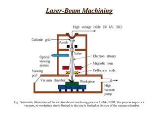
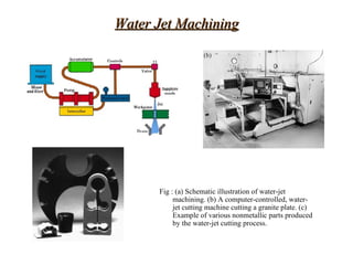
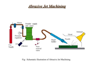
Advanced machining
   processes and
  Nanofabrication


  Chapter 26
Introduction
•   Chemical machining
•   Electro chemical machining
•   Electrical discharge machining
•   Wire EDM
•   Laser beam machining
•   Electron-beam machining and plasma-arc
    cutting
•   Water-jet machining
•   Abrasive-jet machining
•   Nanofabrication
•   Micro machining
•   Economics of advanced machining process
Situations where processes are not
  satisfactory, economical or even possible

•   High hardness and the strength of the material
•   Work-piece too flexible
•   Complex shape
•   Surface finish and dimensional tolerances
•   Undesirable Temperature rise and dimensional
    tolerances
Examples of parts made by advanced Machining
                   Processes


Fig : Examples of parts made by advanced machining processes. These parts are made by advanced machining
      processes and would be difficult or uneconomical to manufacture by conventional processes. (a) Cutting
      sheet metal with a laser beam.(b) Microscopic gear with a diameter on the order of 100µm, made by a special
      etching process.
Chemical machining
 Chemical attacks metals and etch them by removing small
   amounts of material from the surface using reagents or etchants


Fig : (a) Missile skin-panel section contoured by chemical milling to improve the stiffness-to weight
     ratio of the part. (b) Weight reduction of space launch vehicles by chemical milling aluminum-alloy
     plates. These panels are chemically milled after the plates have first been formed into shape by
     processes such as roll forming or stretch forming. The design of the chemically machined rib
     patterns can be modified readily at minimal cost.
Chemical milling:
         milling
• Shallow cavities produced on plates, sheets, forgings, and
  extrusions

Procedure for chemical milling Steps :

1 – Residual stresses should relieved in order to prevent warping
2 – Surfaces to be thoroughly degreased and cleaned
3 - Masking material(tapes,paints,elastomers & plastics ) is applied
4 – masking is peeled off by scribe and peel technique
5 – The exposed surfaces are etched with etchants
6 – After machining the parts to be thoroughly washed to prevent further
   reactions with residue etchant
7 – rest of the masking material is removed and the part is cleaned and
   inspected
8 – additional finishing operations are performed on chemically milled
   parts
9 – this sequence is repeated to produce stepped cavities and various
   contours
Process capabilities:
• Chemical milling used in the aerospace industry
• Tank capacities for reagents are as large as 3.7m
  x15m
• Process also used for micro electronic devices
• Surface damage may result due to preferential etching
  and intergranular attack


Chemical blanking:
• Chemical blanking is similar to chemical milling
• Material is removed by chemical dissolution rather
  than by shearing
• Burr free etching of printed-circuit boards, decorative
  panels, thin sheet metal stampings as well as
  production of small and complex shapes
Chemical Machining


Fig : (a) Schematic illustration of the chemical machining process. Note that no forces or machine tools
     are involved in this process. (b) Stages in producing a profiled cavity by machining; not the
     undercut.
Photochemical blanking :
• Modification of chemical milling
• Material removed from flat thin sheet by photographic
  techniques
Steps for photochemical blanking
• Design is prepared at a magnification of 100x

• Photographic negative is reduced to the size of finished
  part

• Sheet blank is coated with photosensitive material
  (Emulsion)

• Negative placed over coated blank and exposed to ultra
  violet light which hardens the exposed area

• Blank is developed which dissolves the exposed areas

• Blank is then immersed into a bath of reagent or sprayed
  with the reagent which etches away the exposed areas

• The masking material is removed and the part is washed
  thoroughly to remove all chemical residues
Design considerations
•    Designs involving sharp corners,deep & narrow cavities,
    severe tapers or porous work piece should be avoided

• Undercuts may be developed because etchant attacks
  both in horizontal and vertical direction

• To improve production rate the bulk of the work piece
  should be shaped by other machining process priorly

• Dimensional variations can occur ,this can be minimized
  by proper selection of artwork media by controlling the
  environment

• Many product designs are now made with computer
  aided design
Electro Chemical Machining


Fig : Schematic illustration of the electrochemical-machining
     process. This process is the reverse of electroplating.
Electrochemical machining
• This process is reversal of the electro plating

• Electrolyte acts as current carrier

• High rate of electrolyte movement in tool work piece gap washes
  metal ions away from the work piece ( ANODE)

• This is washed just before they have a chance to plate on the tool
  ( cathode)

• Shaped tool made of brass , copper , bronze , or stainless steel

• Electrolyte is pumped at a high rate through the passages in the
  tool

• Machines having current capacities as high as 40,000 A and as
  low as 5A are available
Parts made by Electrochemical Machining


Fig : Typical parts made by electrochemical machining. (a) Turbine blade made of a nickel alloy, 360
     HB; note the shape of the electrode on the right. (b) Thin slots on a 4340-steel roller-bearing cage.
     (c) Integral airfoils on a compressor disk.
Process capabilities

• Used to machine complex cavities in high strength
  material
• Applications in aerospace industry,jet engines parts
  and nozzles
• ECM process gives a burr free surface
• No thermal damage
• Lack of tool forces prevents distortion of the part
• No tool wear
• Capable of producing complex shapes and hard
  materials
Biomedical Implant


Fig : (a) Two total knee replacement systems showing metal implants (top pieces) with an ultrahigh
     molecular weight polyethylene insert (bottom pieces) (b) Cross-section of the ECM process as
     applied to the metal implant.
Design considerations for Electrochemical
 Machining
• Electrolyte erodes sharp surfaces and profiles so not
  suited for sharp edges
• Irregular cavities may not be produced to the desired
  shape with acceptable dimensional accuracy
• Designs should make provisions for small taper for
  holes and cavities to be machined

Pulsed electro chemical machining(PECM)
•  Refinement of ECM
• Uses pulsed rather than direct
• Improves fatigue life, eliminates recast layer left on die
  and mold surfaces by electrical discharge machining
• Very high current densities, but the current is
Electrochemical Grinding
Combines electrochemical machining with conventional grinding


    Fig : Schematic illustration of the electrochemical – grinding process. (b) Thin slot
        produced on a round nickel – alloy tube by this process.
Electrical-Discharge Machining


(a)                                                    (b)                                       (c)


Fig : (a) Schematic illustration of the electrical-discharge machining process. This is one of the most widely used
      machining processes, particularly for die-sinking operations. (b) Examples of cavities produced by the
      electrical-discharge machining process, using shaped electrodes. Two round parts (rear) are the set of dies for
      extruding the aluminum the aluminum piece shown in front. (c) A spiral cavity produced by ECM using a
      slowly rotating electrode, similar to a screw thread.
Examples of EDM

                                                      Fig : Stepped cavities produced with a square
                                                            electrode by the EDM process. The workpiece
                                                            moves in the two principal horizontal
                                                            directions (x-y), and its motion is
                                                            synchronized with the downward movement
                                                            of the electrode to produce these cavities.
                                                            Also shown is a round electrode capable of
                                                            producing round or elliptical cavities.


Fig : Schematic illustration of producing an inner cavity by EDM, using a specially designed
      electrode with a hinged tip, which is slowly opened and rotated to produce the large cavity.
WIRE EDM


           Fig : (a) Schematic
                 illustration of the wire
                 EDM process. As
                 much as 50 hours of
                 machining can be
                 performed with one
                 reel of wire, which is
                 then discarded. (b)
                 Cutting a thick plate
                 with wire EDM. (c) A
                 computer-controlled
                 wire EDM machine.
Laser Beam Machining


Fig : (a) Schematic illustration of the laser-beam machining process. (b) and (c) Examples
                        of holes produced in nonmetallic parts by LBM.
Laser-Beam Machining


Fig : Schematic illustration of the electron-beam machining process. Unlike LBM, this process requires a
         vacuum, so workpiece size is limited to the size is limited to the size of the vacuum chamber.
Water Jet Machining


      Fig : (a) Schematic illustration of water-jet
           machining. (b) A computer-controlled, water-
           jet cutting machine cutting a granite plate. (c)
           Example of various nonmetallic parts produced
           by the water-jet cutting process.
Abrasive Jet Machining


Fig : Schematic illustration of Abrasive Jet Machining
Nanofabrication


Fig : (a) A scanning electron microscope view of a diamond-tipped (triangular piece at the
    right) cantilever used with the atomic force microscope. The diamond tip is attached to
     the end of the cantilever with an adhesive. (b) Scratches produced on a surface by the
       diamond tip under different forces. Note the extremely small size of the scratches.
THE END

Wel

  • 1.
    Advanced machining processes and Nanofabrication Chapter 26
  • 2.
    Introduction • Chemical machining • Electro chemical machining • Electrical discharge machining • Wire EDM • Laser beam machining • Electron-beam machining and plasma-arc cutting • Water-jet machining • Abrasive-jet machining • Nanofabrication • Micro machining • Economics of advanced machining process
  • 3.
    Situations where processesare not satisfactory, economical or even possible • High hardness and the strength of the material • Work-piece too flexible • Complex shape • Surface finish and dimensional tolerances • Undesirable Temperature rise and dimensional tolerances
  • 4.
    Examples of partsmade by advanced Machining Processes Fig : Examples of parts made by advanced machining processes. These parts are made by advanced machining processes and would be difficult or uneconomical to manufacture by conventional processes. (a) Cutting sheet metal with a laser beam.(b) Microscopic gear with a diameter on the order of 100µm, made by a special etching process.
  • 5.
    Chemical machining Chemicalattacks metals and etch them by removing small amounts of material from the surface using reagents or etchants Fig : (a) Missile skin-panel section contoured by chemical milling to improve the stiffness-to weight ratio of the part. (b) Weight reduction of space launch vehicles by chemical milling aluminum-alloy plates. These panels are chemically milled after the plates have first been formed into shape by processes such as roll forming or stretch forming. The design of the chemically machined rib patterns can be modified readily at minimal cost.
  • 6.
    Chemical milling: milling • Shallow cavities produced on plates, sheets, forgings, and extrusions Procedure for chemical milling Steps : 1 – Residual stresses should relieved in order to prevent warping 2 – Surfaces to be thoroughly degreased and cleaned 3 - Masking material(tapes,paints,elastomers & plastics ) is applied 4 – masking is peeled off by scribe and peel technique 5 – The exposed surfaces are etched with etchants 6 – After machining the parts to be thoroughly washed to prevent further reactions with residue etchant 7 – rest of the masking material is removed and the part is cleaned and inspected 8 – additional finishing operations are performed on chemically milled parts 9 – this sequence is repeated to produce stepped cavities and various contours
  • 7.
    Process capabilities: • Chemicalmilling used in the aerospace industry • Tank capacities for reagents are as large as 3.7m x15m • Process also used for micro electronic devices • Surface damage may result due to preferential etching and intergranular attack Chemical blanking: • Chemical blanking is similar to chemical milling • Material is removed by chemical dissolution rather than by shearing • Burr free etching of printed-circuit boards, decorative panels, thin sheet metal stampings as well as production of small and complex shapes
  • 8.
    Chemical Machining Fig :(a) Schematic illustration of the chemical machining process. Note that no forces or machine tools are involved in this process. (b) Stages in producing a profiled cavity by machining; not the undercut.
  • 9.
    Photochemical blanking : •Modification of chemical milling • Material removed from flat thin sheet by photographic techniques
  • 10.
    Steps for photochemicalblanking • Design is prepared at a magnification of 100x • Photographic negative is reduced to the size of finished part • Sheet blank is coated with photosensitive material (Emulsion) • Negative placed over coated blank and exposed to ultra violet light which hardens the exposed area • Blank is developed which dissolves the exposed areas • Blank is then immersed into a bath of reagent or sprayed with the reagent which etches away the exposed areas • The masking material is removed and the part is washed thoroughly to remove all chemical residues
  • 11.
    Design considerations • Designs involving sharp corners,deep & narrow cavities, severe tapers or porous work piece should be avoided • Undercuts may be developed because etchant attacks both in horizontal and vertical direction • To improve production rate the bulk of the work piece should be shaped by other machining process priorly • Dimensional variations can occur ,this can be minimized by proper selection of artwork media by controlling the environment • Many product designs are now made with computer aided design
  • 12.
    Electro Chemical Machining Fig: Schematic illustration of the electrochemical-machining process. This process is the reverse of electroplating.
  • 13.
    Electrochemical machining • Thisprocess is reversal of the electro plating • Electrolyte acts as current carrier • High rate of electrolyte movement in tool work piece gap washes metal ions away from the work piece ( ANODE) • This is washed just before they have a chance to plate on the tool ( cathode) • Shaped tool made of brass , copper , bronze , or stainless steel • Electrolyte is pumped at a high rate through the passages in the tool • Machines having current capacities as high as 40,000 A and as low as 5A are available
  • 14.
    Parts made byElectrochemical Machining Fig : Typical parts made by electrochemical machining. (a) Turbine blade made of a nickel alloy, 360 HB; note the shape of the electrode on the right. (b) Thin slots on a 4340-steel roller-bearing cage. (c) Integral airfoils on a compressor disk.
  • 15.
    Process capabilities • Usedto machine complex cavities in high strength material • Applications in aerospace industry,jet engines parts and nozzles • ECM process gives a burr free surface • No thermal damage • Lack of tool forces prevents distortion of the part • No tool wear • Capable of producing complex shapes and hard materials
  • 16.
    Biomedical Implant Fig :(a) Two total knee replacement systems showing metal implants (top pieces) with an ultrahigh molecular weight polyethylene insert (bottom pieces) (b) Cross-section of the ECM process as applied to the metal implant.
  • 17.
    Design considerations forElectrochemical Machining • Electrolyte erodes sharp surfaces and profiles so not suited for sharp edges • Irregular cavities may not be produced to the desired shape with acceptable dimensional accuracy • Designs should make provisions for small taper for holes and cavities to be machined Pulsed electro chemical machining(PECM) • Refinement of ECM • Uses pulsed rather than direct • Improves fatigue life, eliminates recast layer left on die and mold surfaces by electrical discharge machining • Very high current densities, but the current is
  • 18.
    Electrochemical Grinding Combines electrochemicalmachining with conventional grinding Fig : Schematic illustration of the electrochemical – grinding process. (b) Thin slot produced on a round nickel – alloy tube by this process.
  • 19.
    Electrical-Discharge Machining (a) (b) (c) Fig : (a) Schematic illustration of the electrical-discharge machining process. This is one of the most widely used machining processes, particularly for die-sinking operations. (b) Examples of cavities produced by the electrical-discharge machining process, using shaped electrodes. Two round parts (rear) are the set of dies for extruding the aluminum the aluminum piece shown in front. (c) A spiral cavity produced by ECM using a slowly rotating electrode, similar to a screw thread.
  • 20.
    Examples of EDM Fig : Stepped cavities produced with a square electrode by the EDM process. The workpiece moves in the two principal horizontal directions (x-y), and its motion is synchronized with the downward movement of the electrode to produce these cavities. Also shown is a round electrode capable of producing round or elliptical cavities. Fig : Schematic illustration of producing an inner cavity by EDM, using a specially designed electrode with a hinged tip, which is slowly opened and rotated to produce the large cavity.
  • 21.
    WIRE EDM Fig : (a) Schematic illustration of the wire EDM process. As much as 50 hours of machining can be performed with one reel of wire, which is then discarded. (b) Cutting a thick plate with wire EDM. (c) A computer-controlled wire EDM machine.
  • 22.
    Laser Beam Machining Fig: (a) Schematic illustration of the laser-beam machining process. (b) and (c) Examples of holes produced in nonmetallic parts by LBM.
  • 23.
    Laser-Beam Machining Fig :Schematic illustration of the electron-beam machining process. Unlike LBM, this process requires a vacuum, so workpiece size is limited to the size is limited to the size of the vacuum chamber.
  • 24.
    Water Jet Machining Fig : (a) Schematic illustration of water-jet machining. (b) A computer-controlled, water- jet cutting machine cutting a granite plate. (c) Example of various nonmetallic parts produced by the water-jet cutting process.
  • 25.
    Abrasive Jet Machining Fig: Schematic illustration of Abrasive Jet Machining
  • 26.
    Nanofabrication Fig : (a)A scanning electron microscope view of a diamond-tipped (triangular piece at the right) cantilever used with the atomic force microscope. The diamond tip is attached to the end of the cantilever with an adhesive. (b) Scratches produced on a surface by the diamond tip under different forces. Note the extremely small size of the scratches.
  • 27.