
Recommended
More Related Content
What's hot
What's hot (20)
Viewers also liked
Viewers also liked (20)
Similar to Cutting Tool Materials: Properties and Selection
Similar to Cutting Tool Materials: Properties and Selection (20)
Recently uploaded
Recently uploaded (20)
Cutting Tool Materials: Properties and Selection
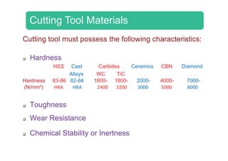
- 1. Cutting Tool MateriCutting Tool Materi Cutting tool must possess thCutting tool must possess th Hardness HSS Cast Carbid Alloys WC Hardness 83 86 82 84 1800Hardness 83-86 82-84 1800- (N/mm²) HRA HRA 2400 Toughness Wear ResistanceWear Resistance Chemical Stability or Inert ialsials he following characteristics:he following characteristics: es Ceramics CBN Diamond TiC 1800 2000 4000 70001800- 2000- 4000- 7000- 3200 3000 5000 8000 ness
- 2. Hardness / Wear RResistance
- 4. Relative time required t various tool materialsvarious tool materials, the tool materials were to machine with indicating the yearindicating the year introduced
- 5. Selection of Cutting FIGURE: The selection of the cutting-tool material conditions for a given application g Tool Materials and geometry followed by the selection of cutting n depends upon many variables
- 6. Cutting Tool Mag terial Hardness
- 7. Properties for GroupProperties for Groupps of Tool Materialsps of Tool Materials
- 8. General Characteristics o Carbon & Alloy High Speed Cast Cobalt Unc Car Steels Steels Alloys Car Hot Hardness Toughnessg Impact Strength Wear Resistance Cutting Speed ThermalThermal Shock Resistance Cost of Tool Material Depth of cut Light to Medium Light to Heavy Light to Heavy Lig He i i hFinish Obtainable Rough Rough Rough Go of Cutting-Tool Materials coated rbides Coated Carbides Ceramics Cubic Boron Diamond rbides Carbides Nitride Increasing Increasingg Increasing IncreasingIncreasing Increasing Increasing IncreasingIncreasing ht to eavy Light to Heavy Light to Heavy Light to Heavy Very Light ood Good Very Good Very Good Excellent
- 9. Alloy steels:Alloy steels: Chromium: Improves strengt and hot hardness. In significa corrosion resistance. Manganese: improves the str Tungsten: increases toughne Mol bden m increases to gMolybdenum: increases toug Nickel: improves strength andNickel: improves strength and Vanadium: inhibits grain grow temperatures thereby enhanc of steelof steel. th, hardness, wear resistance, nt proportions, Cr improves rength and hardness of steel. ess and hot hardness. ghness and hot hardnessghness and hot hardness. d toughness.d toughness. wth during elevated cing strength and toughness
- 10. Carbon SteelsCarbon Steels Hi h C b t l (0 6 t 1 5% CHigh Carbon steel (0.6 to 1.5% Car Small percentages of silicon, mang used to help refine grain size and inused to help refine grain size and in Easily shaped and sharpened Greater resistance to abrasive wea Do not have sufficient hot hardness Widely used for files, saw blades, c Speeds – 5 m/minSpeeds – 5 m/min b )rbon) ganese, chromium and vanadium are ncrease tool hardnessncrease tool hardness ar s (200°C) for cutting at high speeds chisels, taps, broaches and reamers
- 11. High Speed Steel High speed tool steel differs from plain high c steel in the addition of alloying elements to ha strengthen the steel and make it more resistastrengthen the steel and make it more resista (600 0C) Commonly used alloying elements: many y g chromium, tungsten, vanadium, molybde and niobium The M series (10% Mo, with Cr, V, alloying elements) represents tool molybdenum type and the T series V and Cobalt as alloying elements)y g ) the tungsten type. Weq = 2 (%Mo) + %Weq ( ) Some of the High SpeedSome of the High Speed powdered metal (PM) fo carbon arden and ant to heatant to heat nganese,g , enum, cobalt W and Cobalt as steels of the s (18% W, 4% Cr, 1% ) represents those of) p d Steels are now available in ad Steels are now available in a orm.
- 12. Cast Cobalt AlloysCast Cobalt Alloys A typical composition for this cla 21% W, and 2% C which gives a Cast alloys provide high abrasio for cutting scaly materials They are not as tough as HSS a cutting operations. When applying cast alloy tools, t mind and sufficient support shou Speeds – 45 to 60 m/min. ss of tool material was 45% Co, a hot hardness of 750 °C) n resistance and are thus useful and are sensitive for interrupted their brittleness should be kept in uld be provided at all times.
- 13. CarbidesCarbides Also known as cement Because of their high hardness ( thermal conductivity, abrasive re carbides are the most importantp and die materials for a w Most carbide tools in use todayMost carbide tools in use today carbides of W-Ti or W-Ti-Ta, de be ma Speeds – ted or sintered carbides (1000 °C), High elastic modulus, esistance and chemical stability, t, versatile and cost effective tool, wide range of applications y are either straight WC or multiy are either straight WC or multi epending on the work material to chined. 125 m/min.
- 14. Cemented Carbide FIGURE: P/M process for making ce e Inserts emented carbide insert tools.
- 15. Production of WCProduction of WC Blended WC powder produced byBlended WC powder, produced by mixing WC (94%) with Cobalt (6%) in a ball milling press Carbide blending equipment, Ball mill
- 16. Production of WCProduction of WC Blended WC powder is then dried andp compacted using a pill press The compacted powder is then sintered inp p a sintering furnace at 1350 to 1600 °C
- 17. CarbideCarbide Typical carbide inserts with features; round ins The holes in the inserts are stThe holes in the inserts are st InsertsInserts various shapes and chip breaker serts are also available. tandardi ed for interchangeabilitytandardized for interchangeability.
- 18. Methods of attachingMethods of attaching (a) Clamping, and (c) threadless lockpins (d) In inserts to toll holdersinserts to toll holders (b) Wing lockpins sert brazed on a tool shank
- 19. Boring Head FIGURE: Boring head with carbide insert cuttin cause the chips to curl tightly and br ng tools. These inserts have a chip groove that can reak into small, easily disposed lengths.
- 20. Insert StrengthInsert Strength FIGURE: Relative edge strength and tendency for chipping and breaking of inserts with various shapeschipping and breaking of inserts with various shapes. Strength refers to that of the cutting edge shown by the included angles. Source: Courtesy of Kennametal, Inc. F s FIGURE: Edge preparations for inserts to improve edge strength. Source: Courtesy of Kennametal, Inc.
- 21. Coated Carbide To Necessity: New alloys and en strength and toughness Thesestrength and toughness. These chemically reac Need for improving the performaNeed for improving the performa materials has led to import Coated tools don’t perform The thickness of these coa Speeds – ools ngineered materials, which have high e materials are generally abrasive ande materials are generally abrasive and ctive with tool materials. ance in machining common engineeringance in machining common engineering tant developments in coated tools. m efficiently at low cutting speeds. atings is on the order of 2 to 10 µm. 200 to 250 m/min.
- 22. Coating MaterialsCoating Materials CTitanium Nitride: (Gold Color) Titanium Carb (Gray Color Low friction ffi i t These ticoefficients, high hardness, i t t coatings WC inse have hig fl kresistance to high temperature d d flank we resistan in hi iand good adhesion to the substrate. machinin abrasiv material bide: r) Ceramics: (Black Color) e High chemical inertness lowon erts gh inertness, low thermal conductivity, high thermal stabilityear ce thermal stability, resistance to flank and crater wear. However ceramicng ve ls. However ceramic coatings bond weakly to the substratesubstrate.
- 23. Cutting inserts indicating the diverse range of shapes
- 24. Coating Materialsg Diamond Coatings: Effective in machining abrasive materials Tool life will be improved by ten f ld h d t thfolds when compared to other coated tools. Poor adherence characteristics and difference in thermal expansion between diamond and substrate materialsand substrate materials. Titanium Carbo NitrideTitanium Carbo-Nitride coatings: Normally appears as the intermediate layer of two or three phase coatings. Acts as a neutral layerActs as a neutral layer, helping the other coating layers to bond into a sandwich-like structure.
- 25. Triple Coated Carbp FIGURE: Triple-coated carbide tools provide machining of steel, abrasive wear in c bide Tools resistance to wear and plastic deformation in cast iron, and built-up edge formation.
- 26. Triple Coated Carb FIGURE: Triple-coated carbide tools provid hi i f t l b i imachining of steel, abrasive wear in bide Tools de resistance to wear and plastic deformation in t i d b ilt d f tin cast iron, and built-up edge formation.
- 27. Multiphase CoatingMultiphase Coating The first layer The inter lThe first layer should bond well with the substrate layer s bond wel compatib b th thsubstrate both the High speed, continuous Heavy contincontinuous cutting: TiC/Al2O3 contin cutti TiC/Al2O gsgs The outer layer should rmediate h ld layer should resist wear and have low thermal should l and be ble with l thermal conductivity layers. duty, uous Light, interrupted tti uous ng: O3/TiN cutting: TiC/TiC + TiN/TiN
- 28. Multiphasep Multiphase coatings on a tungsten carbide sub are separated by very thin layers of titanium coatings have been made. Coating thickn e Coatingsg bstrate. Three alternating layers of aluminum oxide nitride. Inserts with as many as thirteen layers of esses are typically in the range of 2 to 10 m..
- 29. CVD Process:CVD Process: FIGURE: Chemical vapor deposition is used to apply layers (TiC, TiN, etc.) to carbide cutting tools.
- 30. PVD ProcessPVD Process FIGURE: Schematic of PPVD evaporation process
- 31. Ceramics (Cement( Ceramics are non-metallic materia The main constituent is Al2O3 , up Extremely high resistance to Extremely high hot hardness (1400 The application of ceramic cutting tooThe application of ceramic cutting too brittleness. The transverse rupt The strength of ceramics under compressg p tools and they can be used To use ceramic tools successfully, insert sh capability set up and general machcapability, set-up, and general mach ted Oxides)) als produced by sintering process. pto 10% oxides of Mg, Ti and Cr abrasive wear and cratering. 0 °C) and low thermal conductivity ols is limited because of their extremeols is limited because of their extreme ture strength (TRS) is very low. ion is much higher than HSS and carbideg at speeds upto 250 m/min. ape, work material condition, machine tool hining conditions must all be correcthining conditions must all be correct.
- 32. Various sizes and shapes of hhot and cold pressed ceramics
- 33. Sialon (Si Al O N)Sialon (Si-Al-O-N) P d d b illi tProduced by milling tog nitride, alumi Dried and pressed to s temperature of Sialons are considerabl Can be used success involving inte Cutting speeds – th Si N Al i igether Si3N4, Aluminium ina and yttria. shape and sintered at a f about 1800 °C ly tougher than alumina. sfully during machining errupted cuts. 200 to 300 m/min.
- 34. CermetsCermets C t b i ll bCermets are basically a comb carb The manufacturing process process used for ho The materials, approximately The strength of cermets is gr ceramics. Therefore, cermets, cu However, when compared to s 30% TiC i t d30% TiC in cermets decre resistance to bi ti f i d tit ibination of ceramic and titanium bide. s for cermets is similar to the ot pressed ceramics. y 70% ceramic and 30 % TiC. reater than that of hot pressed s perform better on interruptedp p uts. solid ceramics, the presence of th h t h d deases the hot hardness and abrasive wear.
- 35. DiamondDiamond Diamond is the hard Diamond tools have high conductivity very low friconductivity, very low fri most materials, the abi edge for a long time and Diamond cutting tools sho finishing cuts of precision b li ht d dbe very light and speeds 5000 S dest material known h hardness, good thermal ction non adherence toction, non-adherence to ility to maintain a sharp a good wear resistance. ould only be used for light n surfaces. Feeds should ll i fs are usually in excess of SFPM
- 36. Disadvantages of DDisadvantages of D Rigidity in the machine tool Because diamonds are p affinity for the carbon in the f they can only be usedthey can only be used Diamond has a tendency toDiamond has a tendency to (7000 C) to graphite Diamond is very brittle and too DiamondDiamond and the setup is very critical pure carbon, they have an ferrous materials. Therefore, on non-ferrous metalson non-ferrous metals. revert at high temperaturesrevert at high temperatures and/or oxidize in air. costly to shape into cutting ols.
- 37. Polycrystalline Di d T lDiamond Tools FIGURE: Polycrystalline diamond tools are carbides with diamond inserts. They are restricted to simple geometries.
- 38. Polycrystalline diamond mateerial bonded to a carbide base.
- 39. Polycrystalline Cubic BPolycrystalline Cubic B CBN is similar to diamond in itCBN is similar to diamond in it is also bonded (a layer of 0.5 t bas While the carbide provides sho provides very high wear re stren With the exception of titanium, CBN will work effectively as a work mawork ma CBN should mainly be con material because of its extremmaterial because of its extrem Machine tool and set-up rigiditMachine tool and set up rigidit criti Boron Nitride (PCBN)Boron Nitride (PCBN) ts polycrystalline structure andts polycrystalline structure and to 1.0 mm PCBN) to a carbide se. ock resistance, the CBN layer esistance and cutting edge ngth. , or titanium alloyed materials, cutting tool on most common aterialsaterials. nsidered as a finishing tool me hardness and brittlenessme hardness and brittleness. ty for CBN as with diamond isty for CBN as with diamond is cal
- 40. Cubic BoroCubic Boro Construction of a polycrystalline cubic boron nitride or a diamond layer on a tungsten-carbide i tinsert. on Nitrideon Nitride Inserts with polycrystalline cubic boron nitride tips (top row) and solid polycrystalline cBN i t (b tt )inserts (bottom row).
- 41. Improvements in Cp FIGURE: Improvements in cutting tool materials (and productivity Cutting speedsg p have led to significant increases in cutting speeds y) over the years.
- 42. Approximate Cost of SApproximate Cost of S TABLE Tool High-speed steel tool bitsHigh speed steel tool bits Carbide-tipped (brazed) tools for turning Carbide inserts, square 3/16"thick Plain CoatedCoated Ceramic inserts, square Cubic boron nitride inserts, square Diamond coated insertsDiamond-coated inserts Diamond-tipped inserts (polycrystalline) Selected Cutting ToolsSelected Cutting Tools Size (in.) Cost ($) 1/4 sq.x 2 1/2 long 1–21/4 sq.x 2 1/2 long 1 2 1/2 sq. x 4 3–7 1/4 sq. 2 3/4 sq 43/4 sq. 4 1/2 inscribed circle 5–9 6 106–10 1/2 inscribed circle 8–12 1/2 inscribed circle 60–90 1/2 inscribed circle 50 601/2 inscribed circle 50–60 1/2 inscribed circle 90–100