Downloaded 225 times

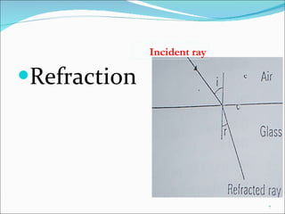
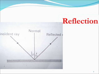
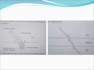
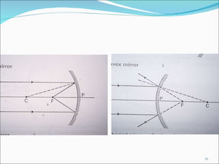
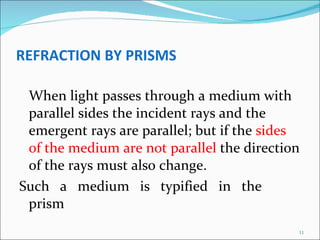
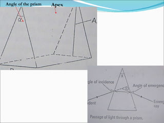
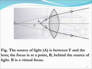
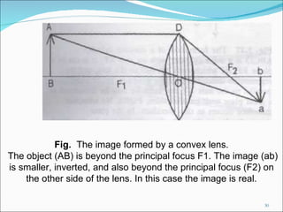
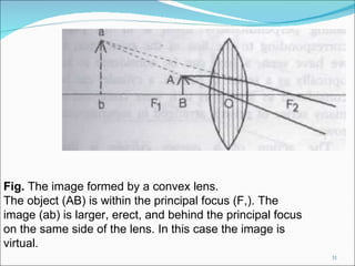
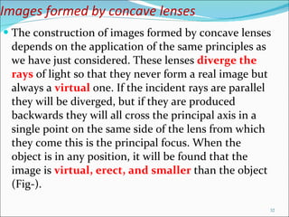
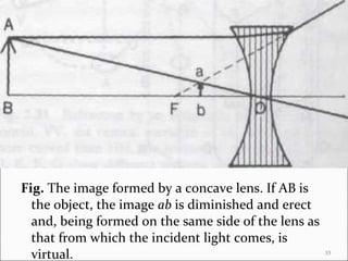
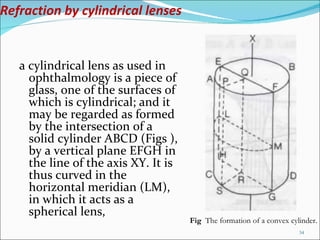
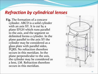
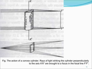
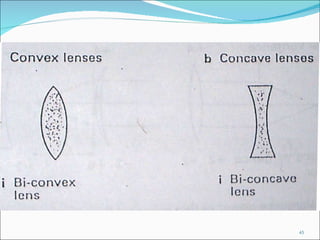
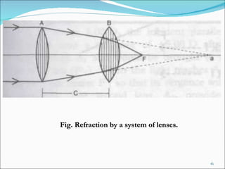
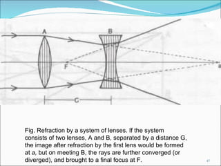
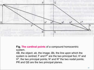


The document discusses the properties and behavior of light, including reflection, refraction, and how different materials and optical components like lenses interact with light. It explains how lenses can refract light to form real or virtual images, and the factors that determine the type of image formed such as whether the object is between the focal point and lens or beyond it. Different lens shapes and cylindrical lenses are also described.


![[Unit 12.3] lens](https://cdn.slidesharecdn.com/ss_thumbnails/unit12-3lens-100829070431-phpapp02-thumbnail.jpg?width=640&height=640&fit=bounds)


![PERI-PROSTHETIC FRACTURE NAIL-PLATE CONSTRUCT [NPC].pptx](https://cdn.slidesharecdn.com/ss_thumbnails/drarunkumardrmohamedashrafperiprostheticfrasturenail-plateconstructnpc-260209164459-7e9d15a1-thumbnail.jpg?width=640&height=640&fit=bounds)


