Downloaded 5,932 times
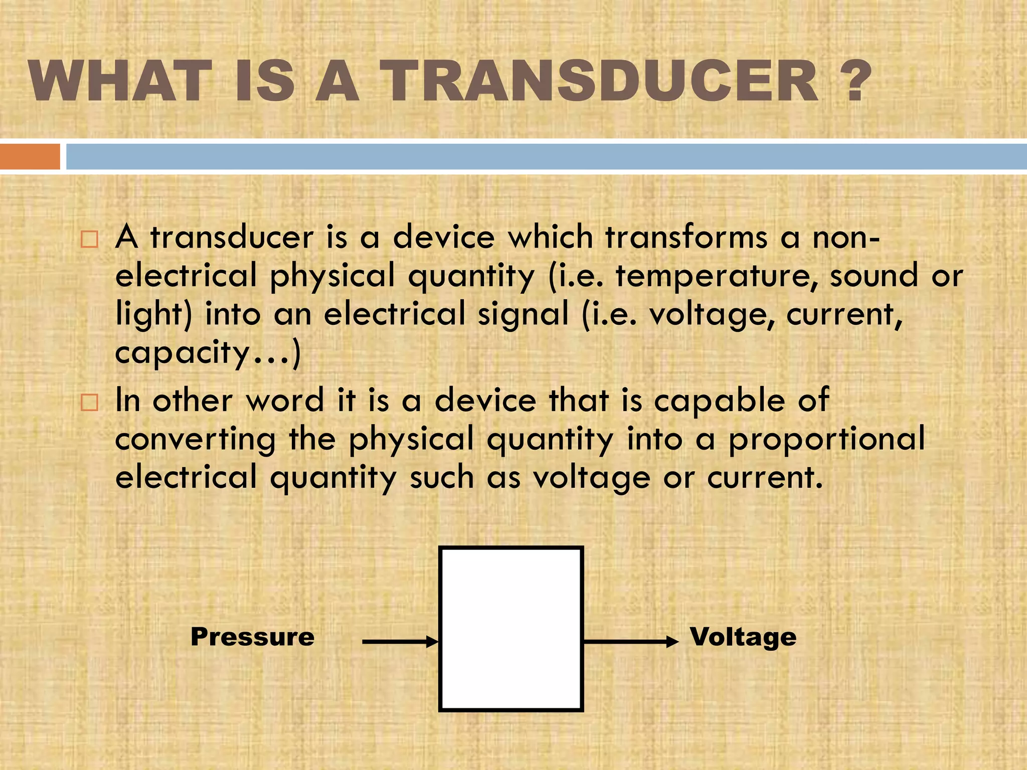
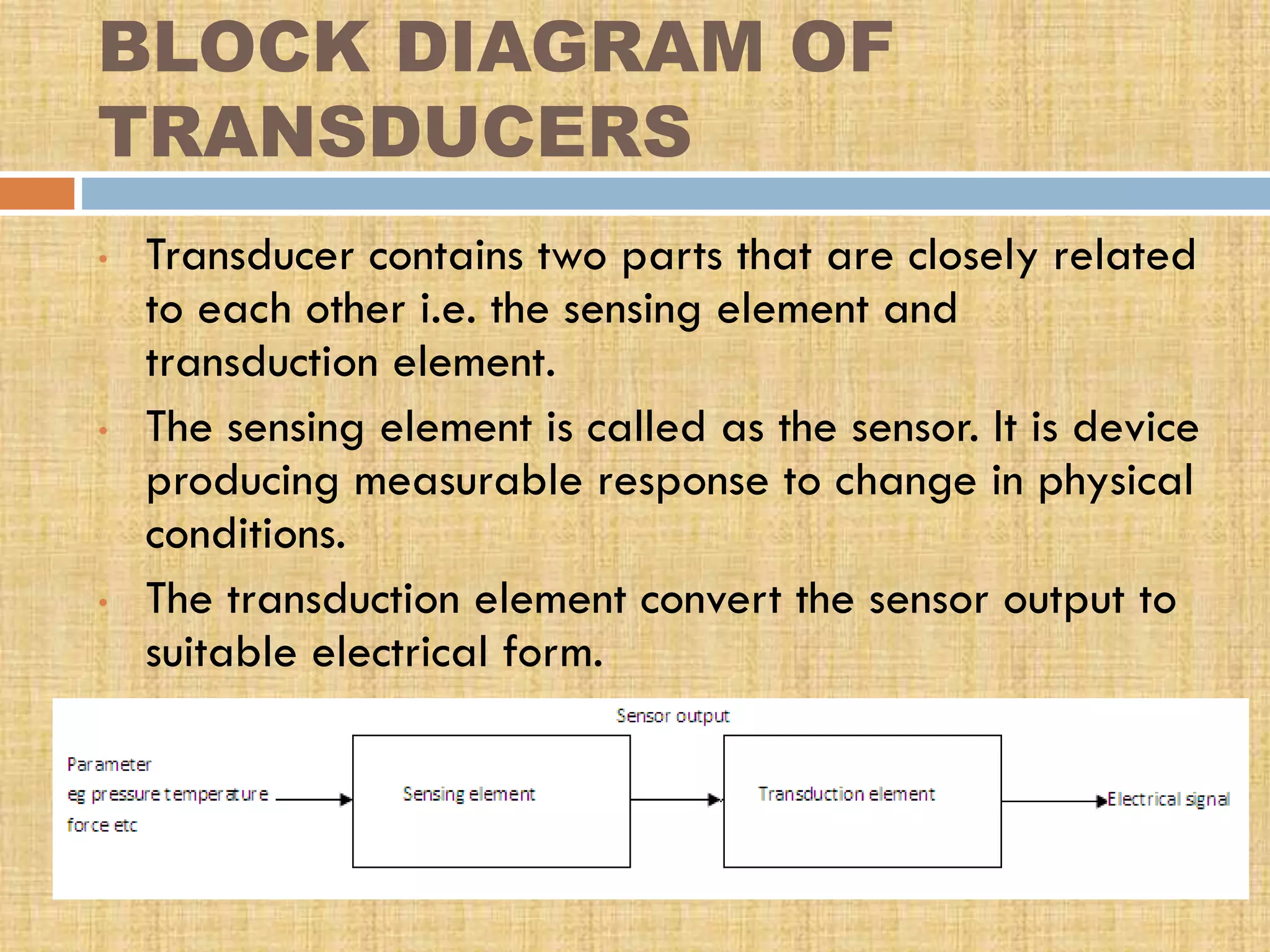

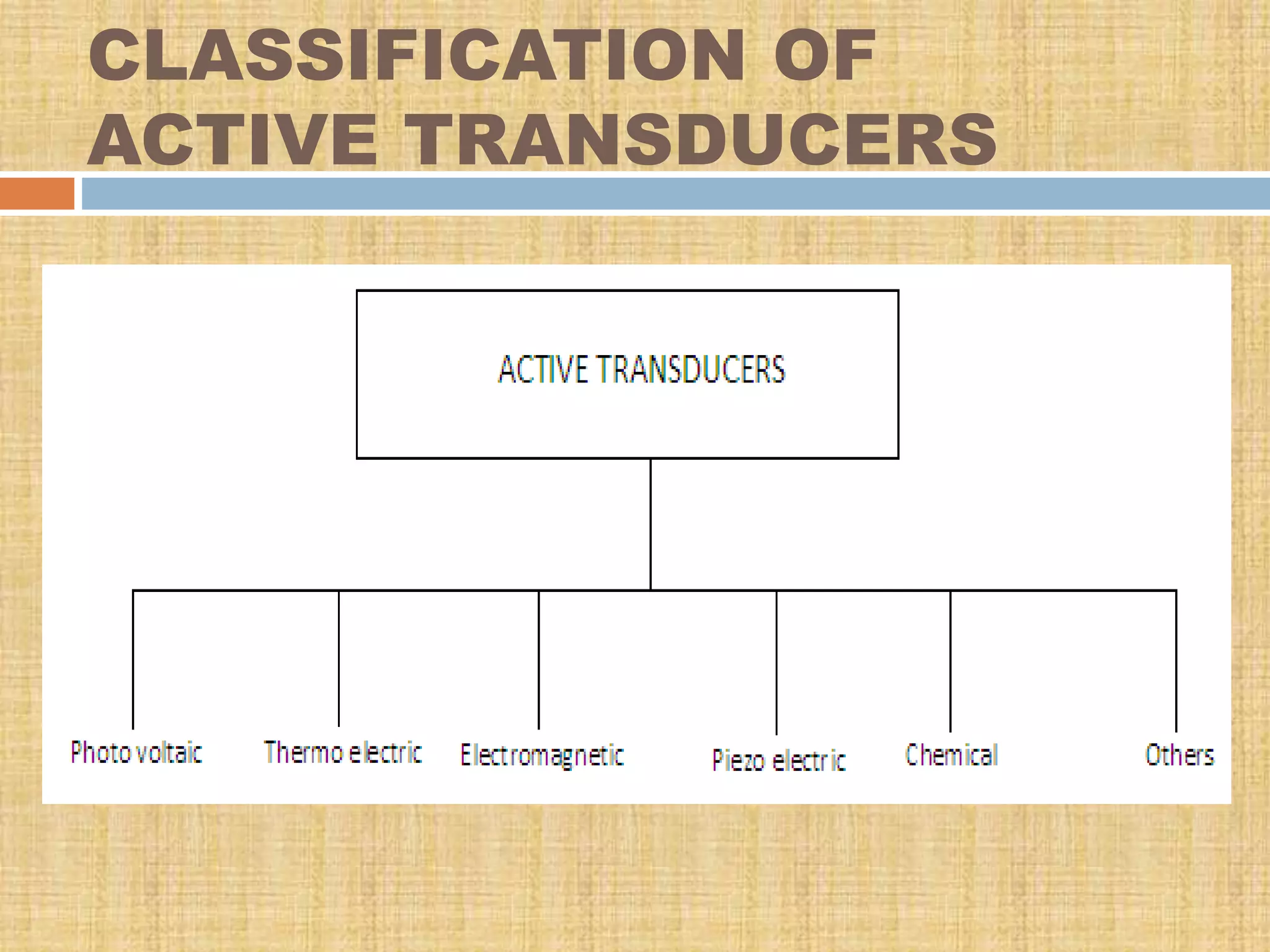
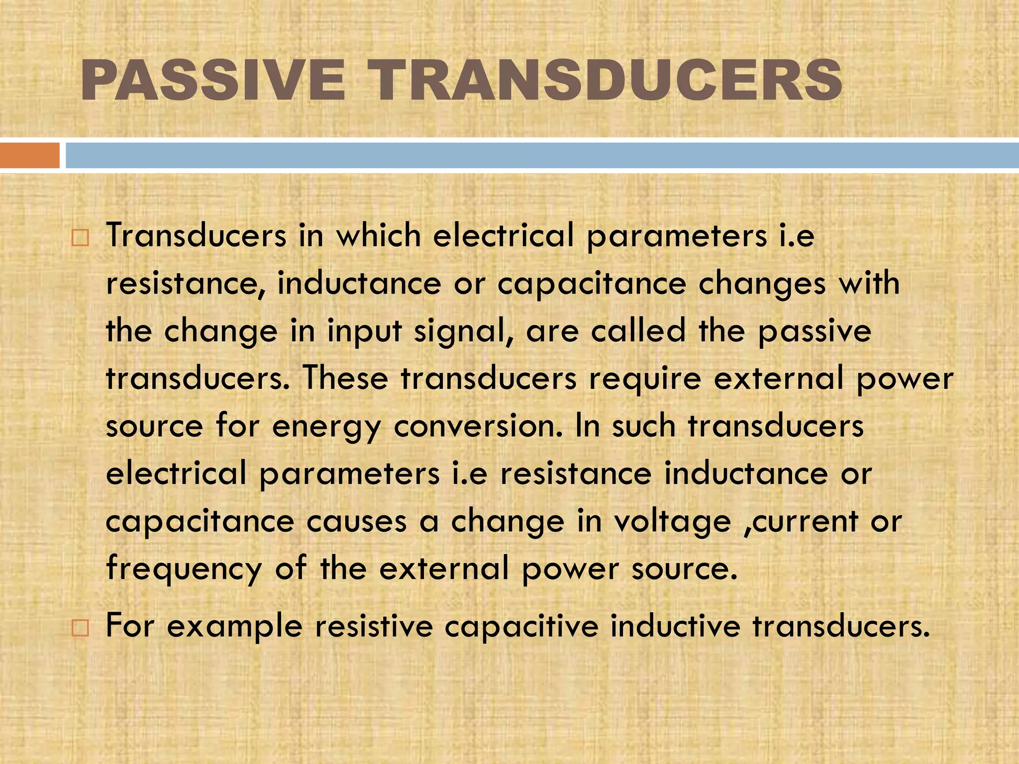
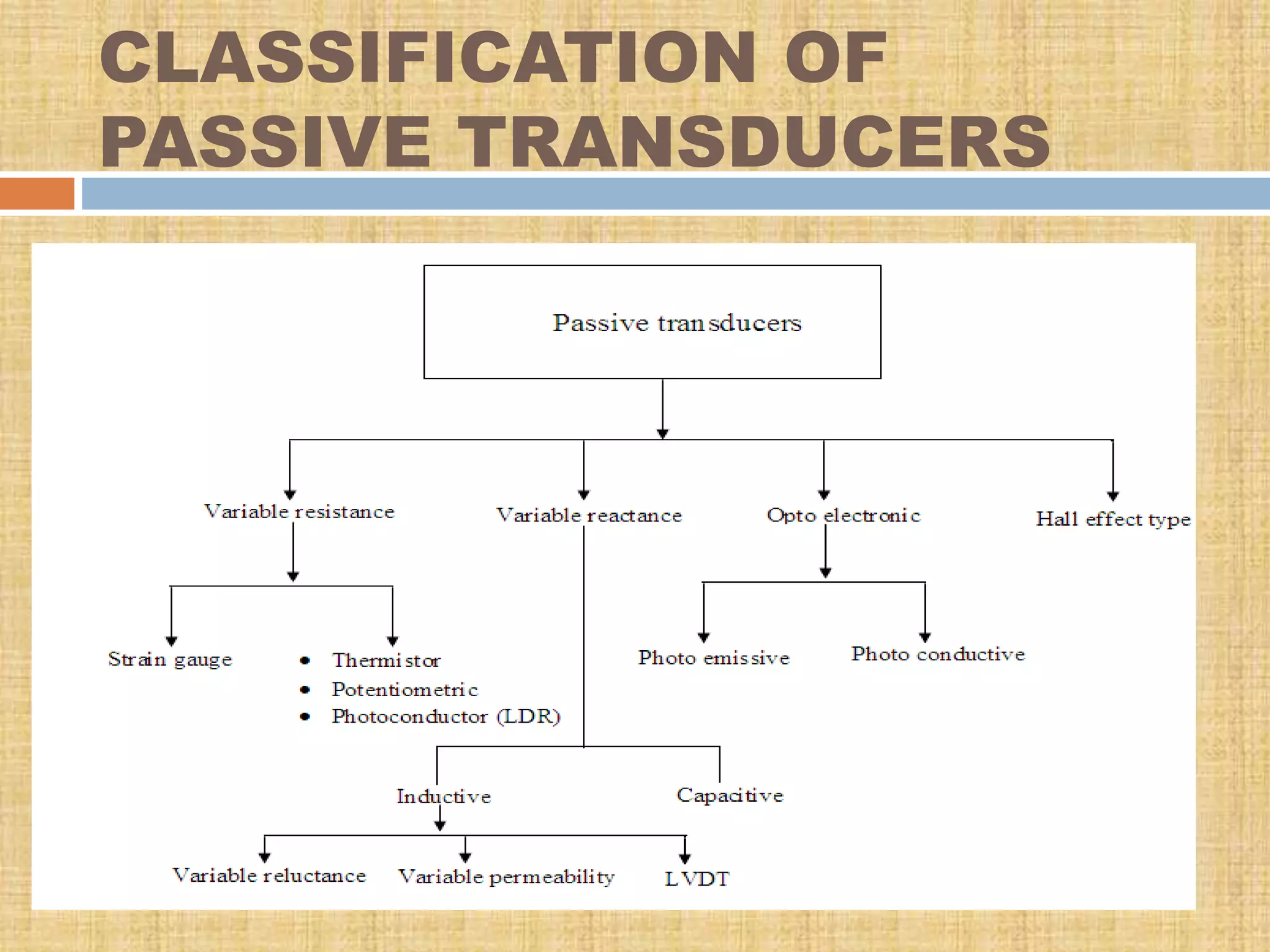
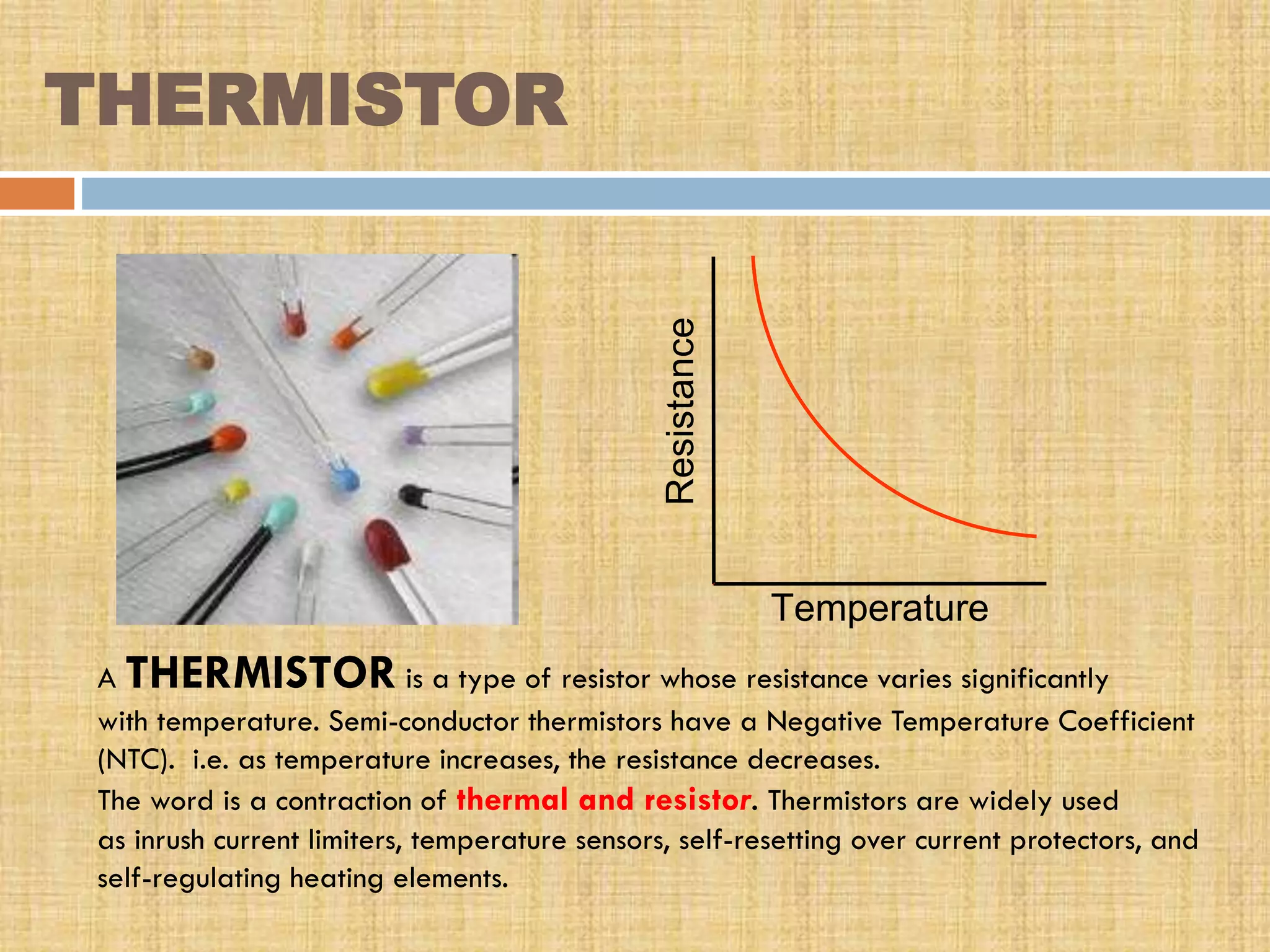
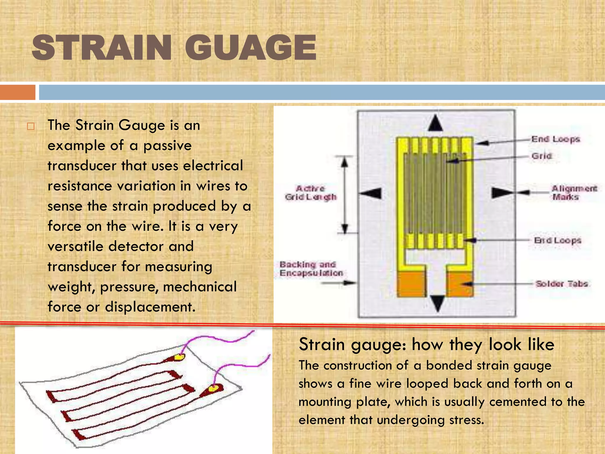
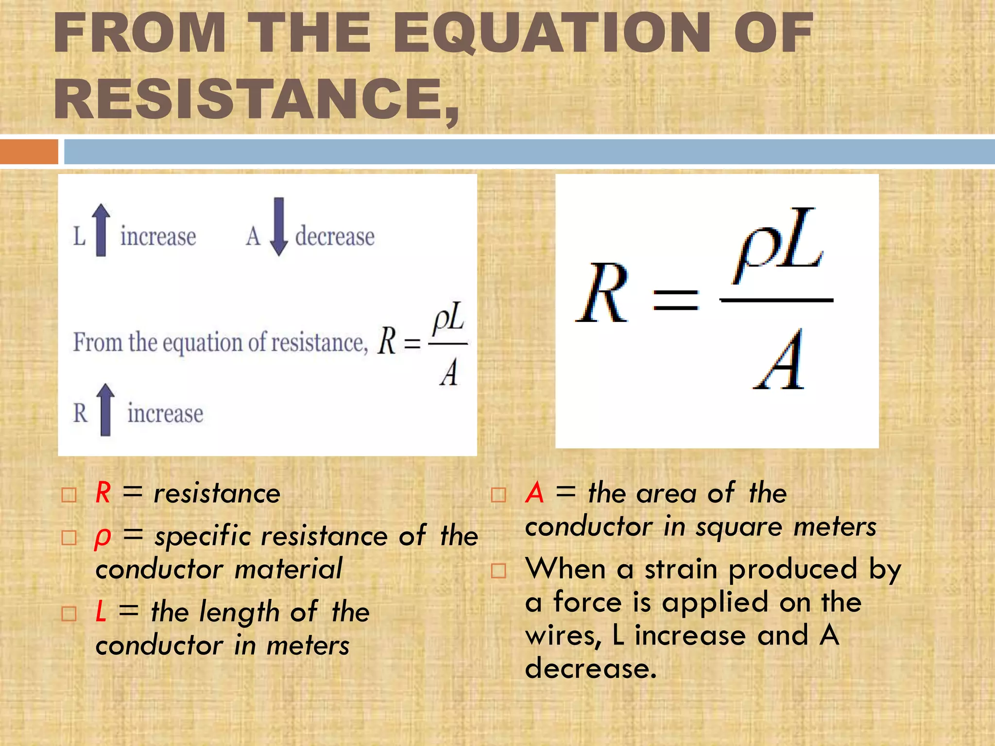
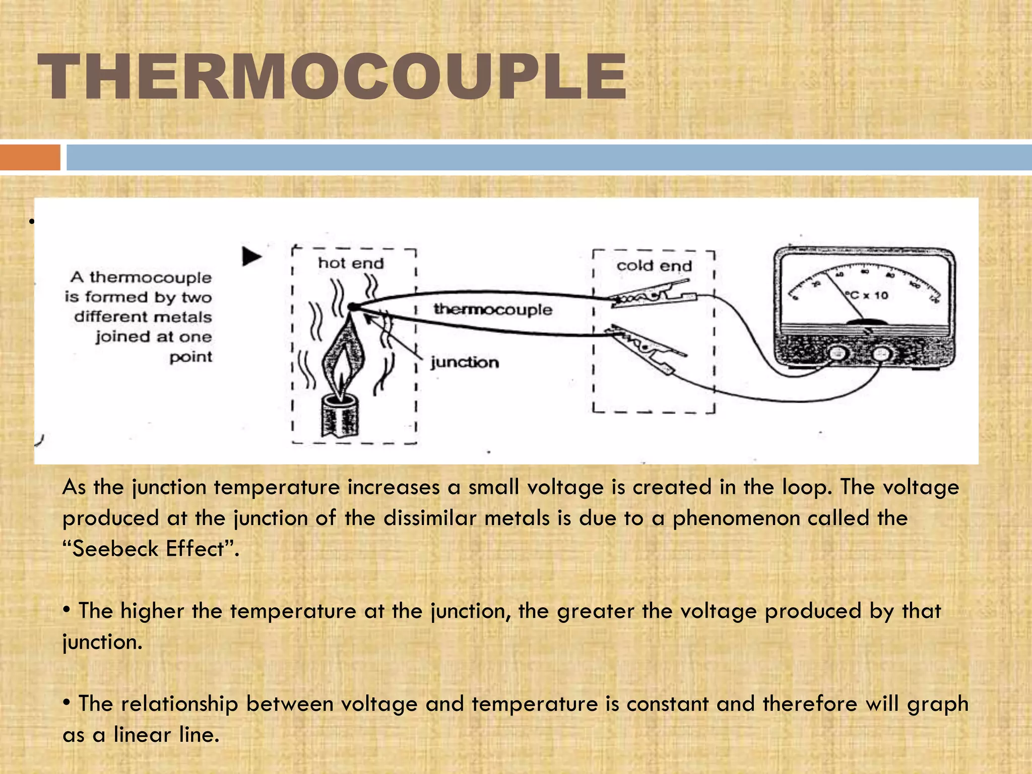


This document provides an overview of transducers. It defines a transducer as a device that converts a non-electrical physical quantity into an electrical signal. Transducers contain a sensing element that produces a measurable response to physical changes and a transduction element that converts the sensor output into an electrical form. Transducers are classified based on their output signal type (analog or digital), application method (primary or secondary), energy conversion method (active or passive), and transduction principle used (resistive, capacitive, inductive, etc.). Examples of common transducers discussed include thermocouples, strain gauges, thermistors, and linear variable differential transformers. Selection factors and applications of transducers


