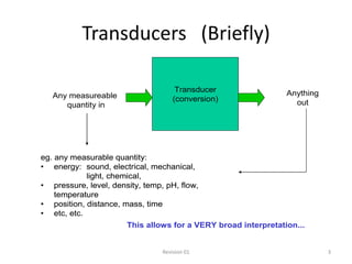
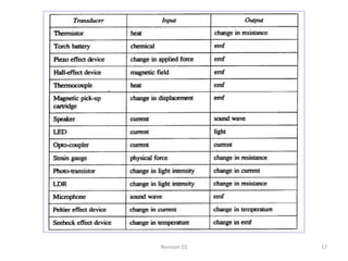
Transducers
Transducers
• Definition: Technically…
• A device that converts one energy form to another
  (eg, mechanical to electrical).
• Any device or component that converts an input signal of one
  form to an output signal of another form
• An element or device which receives information in the form
  of one quantity and converts it to information in the same or
  an other quantity or form.
• A device for translating the magnitude of one quantity into
  another quantity.


                             Revision 01                          2
Transducers (Briefly)

                                      Transducer                Anything
   Any measureable                   (conversion)
      quantity in                                                 out


eg. any measurable quantity:
• energy: sound, electrical, mechanical,
            light, chemical,
• pressure, level, density, temp, pH, flow,
    temperature
• position, distance, mass, time
• etc, etc.
                       This allows for a VERY broad interpretation...


                                 Revision 01                               3
Transducers
Definition: Practical and realistic…
• A sensor that converts one energy form to
  another (eg. mechanical to electrical).
 eg.                             Things that AREN’T generally referred
 • Microphone                    to as transducers:
 • Thermocouples                 • Valves
 • Thermistors                   • Motors
 • Tacho-generators              • Solenoids
 • a diode can be used           • Alarms
   to measure temperature.       • Contactor
 • pH probe                      • Heater
 • Ultrasonic level detector     • Power transformer
 • etc, etc.                     • Hydraulic cylinder


                               Revision 01                               4
Types and applications
Some common transducers and common uses
• Thermistor/thermocouple temperature eg;motors
• LDRs/LEDs               flame or smoke
• Opto-coupler                   data transfer
• Speaker/microphone             acoustic/sound
• Magnetic pickup                stylus/vibration
• Strain guage                   tension
• Hall effect                   magnetism
• Peltier effect device          temperature
• Piezzo                         stress/pressure


                           Revision 01              5
Quantities and units
           Parameter     Unit – NB : Shaded boxes indicate a base SI unit.
                                     Name                              Symbol
Mass                                Kilogram                             kg
Length / Displacement                Metre                               m
Velocity                       Metres per second                         m/s
Temperature (SI)                     Kelvin                                  K
Temperature (Alt)                   Celsius                             C
Acceleration               Metres per second squared                 m/s2 (m/s/s)
Light Intensity                     Candela                              cd
Illuminance                           Lux                                    lx
Force                               Newtons                                  N
Pressure                   Pascal (Newton per square                     Pa
                                      metre)
Sound level (relative)               Decibel                             dB
Magnetic Flux Density       Tesla (Webers per metre                  T (Wb/m2)
                                     squared)
Time                                 Second                                  s
Current                             Ampere                                   A


                                   Revision 01                                      6
Classification of transducers
• There are many ways to classify transducers:
   – By what they are measuring
      • General classification.
      • Specific classification.
   – By the output signal type.
   – By whether or not they produce their own supply. (Active
     or Passive)
   – Input to output.
   – Contact type or not
   – Direct or indirect.
   – Method used to sense input.

                                   Revision 01                  7
Transducer parameters
• Transducer operating characteristics are usually
  defined by a number of parameters.
• Some of the main parameters to be considered are:
   –   Sensitivity     – Range                 – Span
   –   Linearity       – Hysteresis – Accuracy
   –   Precision (Reproducibility, Repeatability)
   –   And others.


                               Revision 01              8
Hysteresis
A transducer should
produce the same output
                                                       Ideal –
whether the value has                                  Negligible
been reached due to a                     Hysteresis   Hysteresis
continually increasing
input or a continually

                                 Output
decreasing input.


                                             Input


                          Revision 01                               9
Accuracy
  Accuracy can be expressed as a comparison of the
  static error of the transducer compared to the actual
  value (at full scale) expressed as a percentage of full
  scale. (Accuracy may also be expressed in other
  ways.)

                (Measured value – Actual value) x 100
% Accuracy =
                             Actual value
   E.g. A temperature transducer that reads 102 C
   at full scale, when the temperature is 100 C,
   has an accuracy equal to 2% of full scale.

                           Revision 01                      10
Precision (Reproducibility, Repeatability)
The ability of the transducer to produce the same
output each time the same input is applied.


      Poor Accuracy    Poor Accuracy    Good Accuracy
      Poor Precision   Good Precision   Good Precision


                         Revision 01                     11
Sensitivity

Sensitivity is the ability of the transducer to generate
an output for a given change in input.

                         Change in output
Sensitivity =
                           Change in input
E.g. A thermocouple that increases output
voltage by 3mV per degree Celsius temperature
change has a sensitivity of 3mV/ C

                          Revision 01                      12
Range
The highest and lowest values that the
transducer is designed to measure.

E.g. A Temperature transducer may have a range
of –50 C to +50 C


                     Revision 01             13
Span
•The difference between the upper and lower
values the transducer is designed to measure.

•E.g. A Temperature transducer that has a range
of –50 C to +50 C has a span of 100 C


                     Revision 01                14
Linearity
Linearity refers to the change in output
compared to the change in input. If the change
in output is proportional to the change in
input, the transducer is said to be linear.


                     Revision 01                 15
Units we need to know.


       Revision 01       16
Revision 01   17
Measuring temperature

                 Thermocouple


                 Thermistor


         Revision 01            18
Thermocouples


As the junction temperature increases a small voltage is created in the loop.
The voltage produced at the junction of the dissimilar metals is due to a
phenomenon called the “Seebeck Effect”.

• The higher the temperature at the junction, the greater the voltage
produced by that junction.

• The relationship between voltage and temperature is constant and
therefore will graph as a linear line.
Thermistors
• Thermistors are made from
  semi-conductor materials.
• Semi-conductor thermistors


                                         Resistance
  have a Negative
  Temperature Coefficient
  (NTC). i.e. as temperature
  increases, the resistance
  decreases.

                                                      Temperature


                           Revision 01                              20
Thermistor construction
• Thermistors come in a
  variety of sizes and
  shapes.
• Beads, disks, rods and
  probes are some of the
  more common styles.


                       Revision 01   21
Thermistors (Cont)
               Like RTDs, thermistors are
                  often enclosed in a
                  housing suitable for
                  either contact or non-
                  contact applications in
                  industry.


       Revision 01                      22
Transducers (Briefly)
     Bridge circuits                              +10V


                                                          Unknown
                           R1 = 250Ω                      (initially 250Ω)
Use:
   Weighers
   Conveyors (Tonnes/Hr)
   Pressure                                    Vout
   RTD Temperature measurement


                           R1 = 250Ω                     R1 = 250Ω


                                                  0V


                                 Revision 01                            23
Wheatstone bridge
A circuit invented by Sir Charles Wheatstone in
the mid-1800s. It is essentially two matched
voltage dividers with a galvanometer across the
network to sense any difference in potential.
  +
      R1           R3
             mV


      R2            R4
  _
           Transducers (e.g.
           Thermistors or RTDs)
           can replace the resistors.

                      Revision 01                 24
Optical devices
• Many measurement and control systems
  utilise light and light-intensity as a way of
  detecting other physical properties.
• Using direct or reflected light can provide an
  ideal non-contact sensing mechanism.


                       Revision 01                 25
Photoelectric Transducers

Photoelectric transducers are devices that produce an
electrical variation in response to a change in light
intensity, or produce a light intensity variation due to a
change in applied electrical energy. Photoelectric
transducers operate in three classifications, they are:

               • Photoconductive,
                 • Photovoltaic,
                • Photoemissive.
Photoconductive

The photoconductive device is a semiconductor cell which
produces a change in it’s resistance in response to a change in
light intensity.

The three most common photoconductive transducers are the

                • Light Dependant Resistor (LDR),
                        • Phototransistor
                          • Photodiode.
Light Dependant Resistor
Light dependant resistors LDRS
   • The LDR is a
     semiconductor
     device.
   • Its resistance is
     dependant on the
     light intensity that
     falls on the device.


                     Revision 01   29
Light dependant resistors
• As the light intensity
  increases, the
  resistance of the LDR
  decreases.


                                       Resistance
• The LDR is a non-linear
  device with resistance
  ranging from about 10
  MΩ in complete
  darkness to 100Ω in full
  sunlight.                                         Light Intensity (cd)


                         Revision 01                                       30
Phototransistor
• The phototransistor is a
  three-layer semiconductor
  device with a light-sensitive
  collector-base p-n junction.
• The current flowing through
  the collector emitter circuit
  will be controlled by the
  amount of light falling on
  the collector-base junction.


                              Revision 01   31
As light intensity increases, the base-collector junction
 resistance of the phototransistor decreases. This decrease in
resistance increases the base current that in turn increases the
                    flow of collector current.
  The relationship between light intensity and current flow is
  generally constant and therefore will graph as a linear line.
     These linear transfer characteristics are shown below.
Solar cell


• As the light (protons) intensity increases, an imbalance of electrons
  and holes are created, which gives an increase to the open circuit
  potential voltage difference and therefore a current flow within a
  circuit. The relationship between light intensity and open circuit
  voltage is not constant and therefore will not graph as a linear line
Light Emitting Diode
        • This LED is a semi conductive P-N
          junction enclosed in a coloured
          case to enhance the colour of the
          light output. Silicon is not used as it
          produces mainly heat rather than
          light.

        • The semi conductive materials
          used in the manufacture of LED’s
          determines the colour of the
          emitted light. By using different
          materials, such colours as
          red, yellow, green, and even
          invisible light spectrums such as
          infra-red can be produced.
Optocouplers
Optocouplers belong to a family of devices used to electrically
isolate circuits.

This isolation may be required to protect circuits from surge
voltages and to filter certain noise.

Photoelectric transducers are effective in producing high
quality fast responding Optocouplers which can be used in
many varying applications.

The basic Optocoupler consists of a photo emissive
device, LED, and a photoconductive
device, phototransistor, contained in a single package
Opto-coupler devices


www.qsl.net


Isolation circuits


                      Revision 01    36
Piezo devices
The principle of piezoelectric action has been known for quite some
time. Materials such as quartz and man made products such as
Barium Titanate and Lead Zirconate demonstrate a characteristic in
that when pressure is applied over one axis, there tends to be a
polarization of electric charge over the adjacent axis. This is
demonstrated below


                               Revision 01                            37
Piezo Devices

Whether they are Piezoelectric or Piezoceramic devices, the
application is very wide, almost wherever we wish to measure
pressure you will find these devices being used. Although not
exhaustive, some examples include;

                        • Pressure switches
                  • Piezoelectric pressure gauges
        • Djfferential pressure measuring transducers, and
                        • Sonar transducers
                     • Vibration detectors etc
                         • Ignition devices
Resistive Strain Gauge
               A Resistive strain gauge
               is a device that converts
               a change in applied force
               into a change in
               produced resistance.

               A strain gauge consists of
               a length of resistive wire
               that is bonded to the
               surface of an object that
               receives an applied
               force.
Acoustic Transducers
Acoustic transducers are devices that convert a variation in
electrical energy into a change in mechanical energy, (physical
vibrations or oscillations, ie. sound waves). Or
conversely, convert a variation in sound wave energy into
electrical energy.
Common examples of acoustic transducers are the:

• Acoustic speakers,
• Acoustic microphone,
• Piezoceramic transducers, and
• Magnetostrictive transducers
• The magnetic field produced in
  the voice coil, when current is
  applied, is at right angles to the
  magnetic field produced by the
  permanent magnet.
• Therefore the two fields attract or
  repel each other depending on the
  polarity of the signal current. This
  attraction and repulsion causes an
  inward or outward movement of
  the voice coil and cone which
  results in sound waves being
  produced.
• The volume and frequency of the
  sound produced is dependant
  upon the amplitude and
  frequency of the input signal
  current.
Microphone
                         Voice Coil   Diaphragm

                                                  Dust Cover
Permanent Magnet                 S


                                                    Sound in
                                 N


     Signal to                   S
     amplifier


                   Revision 01                                 42
Piezoelectric Buzzer

• Piezo electric buzzers and
  speakers are used in a wide
  variety of applications from
  simple low fidelity applications
  such as a warning buzzer to high
  fidelity, high frequency audio
  speaker applications. Regardless
  of the application, the principle
  of piezoelectric operation
  remains a constant.
Displacement Position And Proximity
           Transducers
Float transducers are used in
   tank level monitoring
   applications. These devices
   use a sender that is either a
   switch or some form of
   resistive device. A
   combination of these
   devices can be seen in an
   automotive application
   where the switch is used to
   indicate tank low level and
   the potentiometer sender
   provides a proportional
   indication of actual tank
   level.
Hall Effect Transducers
The Hall Effect describes a condition if current flow in a conductor being affected
by the presence of a magnetic field If an electric current flows through a
conductor in a magnetic field, the magnetic field exerts a transverse force on the
moving charge carriers which tends to push them to one side of the conductor.
This is most evident in a thin flat conductor. A build up of charge at the sides of
the conductors will balance this magnetic influence, producing a measurable
voltage between the two sides of the conductor. The presence of this
measurable transverse voltage is called the Hall effect after E. H. Hall who
discovered it in 1879.
Hall effect
Magnetic reed


    Revision 01   46
Hall effect devices
Hall effect devices can be used
  to:
• Measure the velocity of
  charged particles in a
  magnetic field (flow meter)
• Measure the proximity of
  magnetic materials (Linear
  displacement)
• Detect pulses of magnetism
  e.g. as in a tachometer


                              Revision 01   47
Capacitive Transducers

• Capacitive transducers use a
  changing capacitive reactance
  within the transducer to
  produce a proportional
  output. The typical capacitive
  transducer. is used as a
  proximity device with one
  electrode charged and the
  other affected as it approaches
  in close proximity. The
  surrounding air is used as a
  dielectric to produce a
  reactance that is proportional
  to the distance between the to
  electrodes of the capacitor.
Reed Switches
• The reed switch is an
  encapsulated inductive
  influenced switch that can be
  activated by the presence of a
  magnetic source. These
  devices are common in float
  sensor Tank Level Indicators
  which can be found in the
  liquid Level State management
  system in a modem warship.
  The item at Figure 1below is a
  typical reed switch that may
  be found in a range of these
  types of equipment
Inductive Proximity Sensors
• Inductive proximity sensors rely on the
  effect of a magnet approaching a high turns
  ratio coil that produces a voltage
  proportional to the relative distance of that
  magnetic source from that coil. Another
  variat ion is to have the inductive source
  coupled via the proximity of the magnetic
  field. The sensor generates a magnetic field
  and as the magnetic conductive material
  approaches the magnetic field, it provides a
  decreasingly reluctant path to magnetism.
  This effect is proportional to the distance of
  the object from the sensor and produces an
  increasing output, the closer the object gets
  to the sensor.
Position and displacement measurement
            Potentiometers


• Measurement of displacement with a potentiometer relies
  on the fact that the resistance between the sliding contact
  and the reference end of the resistance element is
  proportional to the distance between the two points.
Linear Variable Differential
             Transformer (LVDT)
• Using AC instead of DC, we
  are able to avoid sliding
  contact between parts if
  we use a variable
  transformer instead of a
  potentiometer. Devices
  made for this purpose are
  called LVDT’s, which stands
  for Linear Variable
  Differential Transformer.
  The design of an LVDT
  looks similar to the layout
  in the diagram at Figure
  below
Tachogenerator

                                 Shaft mounted tacho


Permeant magnet
tacho- generator


                   Revision 01                         53
Tachogenerator


  Revision 01    54

Transducers

  • 1.
  • 2.
    Transducers • Definition: Technically… •A device that converts one energy form to another (eg, mechanical to electrical). • Any device or component that converts an input signal of one form to an output signal of another form • An element or device which receives information in the form of one quantity and converts it to information in the same or an other quantity or form. • A device for translating the magnitude of one quantity into another quantity. Revision 01 2
  • 3.
    Transducers (Briefly) Transducer Anything Any measureable (conversion) quantity in out eg. any measurable quantity: • energy: sound, electrical, mechanical, light, chemical, • pressure, level, density, temp, pH, flow, temperature • position, distance, mass, time • etc, etc. This allows for a VERY broad interpretation... Revision 01 3
  • 4.
    Transducers Definition: Practical andrealistic… • A sensor that converts one energy form to another (eg. mechanical to electrical). eg. Things that AREN’T generally referred • Microphone to as transducers: • Thermocouples • Valves • Thermistors • Motors • Tacho-generators • Solenoids • a diode can be used • Alarms to measure temperature. • Contactor • pH probe • Heater • Ultrasonic level detector • Power transformer • etc, etc. • Hydraulic cylinder Revision 01 4
  • 5.
    Types and applications Somecommon transducers and common uses • Thermistor/thermocouple temperature eg;motors • LDRs/LEDs flame or smoke • Opto-coupler data transfer • Speaker/microphone acoustic/sound • Magnetic pickup stylus/vibration • Strain guage tension • Hall effect magnetism • Peltier effect device temperature • Piezzo stress/pressure Revision 01 5
  • 6.
    Quantities and units Parameter Unit – NB : Shaded boxes indicate a base SI unit. Name Symbol Mass Kilogram kg Length / Displacement Metre m Velocity Metres per second m/s Temperature (SI) Kelvin K Temperature (Alt) Celsius C Acceleration Metres per second squared m/s2 (m/s/s) Light Intensity Candela cd Illuminance Lux lx Force Newtons N Pressure Pascal (Newton per square Pa metre) Sound level (relative) Decibel dB Magnetic Flux Density Tesla (Webers per metre T (Wb/m2) squared) Time Second s Current Ampere A Revision 01 6
  • 7.
    Classification of transducers •There are many ways to classify transducers: – By what they are measuring • General classification. • Specific classification. – By the output signal type. – By whether or not they produce their own supply. (Active or Passive) – Input to output. – Contact type or not – Direct or indirect. – Method used to sense input. Revision 01 7
  • 8.
    Transducer parameters • Transduceroperating characteristics are usually defined by a number of parameters. • Some of the main parameters to be considered are: – Sensitivity – Range – Span – Linearity – Hysteresis – Accuracy – Precision (Reproducibility, Repeatability) – And others. Revision 01 8
  • 9.
    Hysteresis A transducer should producethe same output Ideal – whether the value has Negligible been reached due to a Hysteresis Hysteresis continually increasing input or a continually Output decreasing input. Input Revision 01 9
  • 10.
    Accuracy Accuracycan be expressed as a comparison of the static error of the transducer compared to the actual value (at full scale) expressed as a percentage of full scale. (Accuracy may also be expressed in other ways.) (Measured value – Actual value) x 100 % Accuracy = Actual value E.g. A temperature transducer that reads 102 C at full scale, when the temperature is 100 C, has an accuracy equal to 2% of full scale. Revision 01 10
  • 11.
    Precision (Reproducibility, Repeatability) Theability of the transducer to produce the same output each time the same input is applied. Poor Accuracy Poor Accuracy Good Accuracy Poor Precision Good Precision Good Precision Revision 01 11
  • 12.
    Sensitivity Sensitivity is theability of the transducer to generate an output for a given change in input. Change in output Sensitivity = Change in input E.g. A thermocouple that increases output voltage by 3mV per degree Celsius temperature change has a sensitivity of 3mV/ C Revision 01 12
  • 13.
    Range The highest andlowest values that the transducer is designed to measure. E.g. A Temperature transducer may have a range of –50 C to +50 C Revision 01 13
  • 14.
    Span •The difference betweenthe upper and lower values the transducer is designed to measure. •E.g. A Temperature transducer that has a range of –50 C to +50 C has a span of 100 C Revision 01 14
  • 15.
    Linearity Linearity refers tothe change in output compared to the change in input. If the change in output is proportional to the change in input, the transducer is said to be linear. Revision 01 15
  • 16.
    Units we needto know. Revision 01 16
  • 17.
  • 18.
    Measuring temperature Thermocouple Thermistor Revision 01 18
  • 19.
    Thermocouples As the junctiontemperature increases a small voltage is created in the loop. The voltage produced at the junction of the dissimilar metals is due to a phenomenon called the “Seebeck Effect”. • The higher the temperature at the junction, the greater the voltage produced by that junction. • The relationship between voltage and temperature is constant and therefore will graph as a linear line.
  • 20.
    Thermistors • Thermistors aremade from semi-conductor materials. • Semi-conductor thermistors Resistance have a Negative Temperature Coefficient (NTC). i.e. as temperature increases, the resistance decreases. Temperature Revision 01 20
  • 21.
    Thermistor construction • Thermistorscome in a variety of sizes and shapes. • Beads, disks, rods and probes are some of the more common styles. Revision 01 21
  • 22.
    Thermistors (Cont) Like RTDs, thermistors are often enclosed in a housing suitable for either contact or non- contact applications in industry. Revision 01 22
  • 23.
    Transducers (Briefly) Bridge circuits +10V Unknown R1 = 250Ω (initially 250Ω) Use: Weighers Conveyors (Tonnes/Hr) Pressure Vout RTD Temperature measurement R1 = 250Ω R1 = 250Ω 0V Revision 01 23
  • 24.
    Wheatstone bridge A circuitinvented by Sir Charles Wheatstone in the mid-1800s. It is essentially two matched voltage dividers with a galvanometer across the network to sense any difference in potential. + R1 R3 mV R2 R4 _ Transducers (e.g. Thermistors or RTDs) can replace the resistors. Revision 01 24
  • 25.
    Optical devices • Manymeasurement and control systems utilise light and light-intensity as a way of detecting other physical properties. • Using direct or reflected light can provide an ideal non-contact sensing mechanism. Revision 01 25
  • 26.
    Photoelectric Transducers Photoelectric transducersare devices that produce an electrical variation in response to a change in light intensity, or produce a light intensity variation due to a change in applied electrical energy. Photoelectric transducers operate in three classifications, they are: • Photoconductive, • Photovoltaic, • Photoemissive.
  • 27.
    Photoconductive The photoconductive deviceis a semiconductor cell which produces a change in it’s resistance in response to a change in light intensity. The three most common photoconductive transducers are the • Light Dependant Resistor (LDR), • Phototransistor • Photodiode.
  • 28.
  • 29.
    Light dependant resistorsLDRS • The LDR is a semiconductor device. • Its resistance is dependant on the light intensity that falls on the device. Revision 01 29
  • 30.
    Light dependant resistors •As the light intensity increases, the resistance of the LDR decreases. Resistance • The LDR is a non-linear device with resistance ranging from about 10 MΩ in complete darkness to 100Ω in full sunlight. Light Intensity (cd) Revision 01 30
  • 31.
    Phototransistor • The phototransistoris a three-layer semiconductor device with a light-sensitive collector-base p-n junction. • The current flowing through the collector emitter circuit will be controlled by the amount of light falling on the collector-base junction. Revision 01 31
  • 32.
    As light intensityincreases, the base-collector junction resistance of the phototransistor decreases. This decrease in resistance increases the base current that in turn increases the flow of collector current. The relationship between light intensity and current flow is generally constant and therefore will graph as a linear line. These linear transfer characteristics are shown below.
  • 33.
    Solar cell • Asthe light (protons) intensity increases, an imbalance of electrons and holes are created, which gives an increase to the open circuit potential voltage difference and therefore a current flow within a circuit. The relationship between light intensity and open circuit voltage is not constant and therefore will not graph as a linear line
  • 34.
    Light Emitting Diode • This LED is a semi conductive P-N junction enclosed in a coloured case to enhance the colour of the light output. Silicon is not used as it produces mainly heat rather than light. • The semi conductive materials used in the manufacture of LED’s determines the colour of the emitted light. By using different materials, such colours as red, yellow, green, and even invisible light spectrums such as infra-red can be produced.
  • 35.
    Optocouplers Optocouplers belong toa family of devices used to electrically isolate circuits. This isolation may be required to protect circuits from surge voltages and to filter certain noise. Photoelectric transducers are effective in producing high quality fast responding Optocouplers which can be used in many varying applications. The basic Optocoupler consists of a photo emissive device, LED, and a photoconductive device, phototransistor, contained in a single package
  • 36.
  • 37.
    Piezo devices The principleof piezoelectric action has been known for quite some time. Materials such as quartz and man made products such as Barium Titanate and Lead Zirconate demonstrate a characteristic in that when pressure is applied over one axis, there tends to be a polarization of electric charge over the adjacent axis. This is demonstrated below Revision 01 37
  • 38.
    Piezo Devices Whether theyare Piezoelectric or Piezoceramic devices, the application is very wide, almost wherever we wish to measure pressure you will find these devices being used. Although not exhaustive, some examples include; • Pressure switches • Piezoelectric pressure gauges • Djfferential pressure measuring transducers, and • Sonar transducers • Vibration detectors etc • Ignition devices
  • 39.
    Resistive Strain Gauge A Resistive strain gauge is a device that converts a change in applied force into a change in produced resistance. A strain gauge consists of a length of resistive wire that is bonded to the surface of an object that receives an applied force.
  • 40.
    Acoustic Transducers Acoustic transducersare devices that convert a variation in electrical energy into a change in mechanical energy, (physical vibrations or oscillations, ie. sound waves). Or conversely, convert a variation in sound wave energy into electrical energy. Common examples of acoustic transducers are the: • Acoustic speakers, • Acoustic microphone, • Piezoceramic transducers, and • Magnetostrictive transducers
  • 41.
    • The magneticfield produced in the voice coil, when current is applied, is at right angles to the magnetic field produced by the permanent magnet. • Therefore the two fields attract or repel each other depending on the polarity of the signal current. This attraction and repulsion causes an inward or outward movement of the voice coil and cone which results in sound waves being produced. • The volume and frequency of the sound produced is dependant upon the amplitude and frequency of the input signal current.
  • 42.
    Microphone Voice Coil Diaphragm Dust Cover Permanent Magnet S Sound in N Signal to S amplifier Revision 01 42
  • 43.
    Piezoelectric Buzzer • Piezoelectric buzzers and speakers are used in a wide variety of applications from simple low fidelity applications such as a warning buzzer to high fidelity, high frequency audio speaker applications. Regardless of the application, the principle of piezoelectric operation remains a constant.
  • 44.
    Displacement Position AndProximity Transducers Float transducers are used in tank level monitoring applications. These devices use a sender that is either a switch or some form of resistive device. A combination of these devices can be seen in an automotive application where the switch is used to indicate tank low level and the potentiometer sender provides a proportional indication of actual tank level.
  • 45.
    Hall Effect Transducers TheHall Effect describes a condition if current flow in a conductor being affected by the presence of a magnetic field If an electric current flows through a conductor in a magnetic field, the magnetic field exerts a transverse force on the moving charge carriers which tends to push them to one side of the conductor. This is most evident in a thin flat conductor. A build up of charge at the sides of the conductors will balance this magnetic influence, producing a measurable voltage between the two sides of the conductor. The presence of this measurable transverse voltage is called the Hall effect after E. H. Hall who discovered it in 1879.
  • 46.
  • 47.
    Hall effect devices Halleffect devices can be used to: • Measure the velocity of charged particles in a magnetic field (flow meter) • Measure the proximity of magnetic materials (Linear displacement) • Detect pulses of magnetism e.g. as in a tachometer Revision 01 47
  • 48.
    Capacitive Transducers • Capacitivetransducers use a changing capacitive reactance within the transducer to produce a proportional output. The typical capacitive transducer. is used as a proximity device with one electrode charged and the other affected as it approaches in close proximity. The surrounding air is used as a dielectric to produce a reactance that is proportional to the distance between the to electrodes of the capacitor.
  • 49.
    Reed Switches • Thereed switch is an encapsulated inductive influenced switch that can be activated by the presence of a magnetic source. These devices are common in float sensor Tank Level Indicators which can be found in the liquid Level State management system in a modem warship. The item at Figure 1below is a typical reed switch that may be found in a range of these types of equipment
  • 50.
    Inductive Proximity Sensors •Inductive proximity sensors rely on the effect of a magnet approaching a high turns ratio coil that produces a voltage proportional to the relative distance of that magnetic source from that coil. Another variat ion is to have the inductive source coupled via the proximity of the magnetic field. The sensor generates a magnetic field and as the magnetic conductive material approaches the magnetic field, it provides a decreasingly reluctant path to magnetism. This effect is proportional to the distance of the object from the sensor and produces an increasing output, the closer the object gets to the sensor.
  • 51.
    Position and displacementmeasurement Potentiometers • Measurement of displacement with a potentiometer relies on the fact that the resistance between the sliding contact and the reference end of the resistance element is proportional to the distance between the two points.
  • 52.
    Linear Variable Differential Transformer (LVDT) • Using AC instead of DC, we are able to avoid sliding contact between parts if we use a variable transformer instead of a potentiometer. Devices made for this purpose are called LVDT’s, which stands for Linear Variable Differential Transformer. The design of an LVDT looks similar to the layout in the diagram at Figure below
  • 53.
    Tachogenerator Shaft mounted tacho Permeant magnet tacho- generator Revision 01 53
  • 54.