Part 2 - Sewage & Drainage in Buildings.pdf
•
5 likes•310 views

Sewage and Drainage Systems in Buildings: Wastewater and Rainwater networks

Recommended
More Related Content
What's hot
What's hot (20)
Similar to Part 2 - Sewage & Drainage in Buildings.pdf
Similar to Part 2 - Sewage & Drainage in Buildings.pdf (20)
More from Ignacio J. Palma, Arch PhD.
More from Ignacio J. Palma, Arch PhD. (15)
Recently uploaded
Recently uploaded (20)
Part 2 - Sewage & Drainage in Buildings.pdf
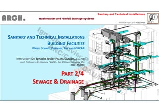
- 1. SANITARY AND TECHNICAL INSTALLATIONS BUILDING FACILITIES WATER, SEWAGE, DRAINAGE, FIRE AND HVAC&R Instructor: Dr. Ignacio Javier PALMA CARAZO, Arch. PhD Assit. Professor / Architecture / CADD – Dar Al Uloom University, KSA 2022 - MMXXII PART 2/4 SEWAGE & DRAINAGE Ignacio Javier PALM A CARAZO ARC/CADD/DAU/KSA
- 2. - WATER SUPPLY: Lecture 01: Introduction Lecture 02: Cold Water Distrbution Systems Lecture 03: Hot Water Production & Supply Systems Lecture 04: Solar Water Heating Systems Lecture 05: Swimminng Pool Treatment Systems Lecture 06: Garden Irrigation System - SEWAGE DISPOSAL – DRAINAGE: Lecture 07: Introduction & Indoor Sewage Network Lecture 08: Outdoor Sewage Network Lecture 09: Rainfalls and Run-off Drainage Systems - FIRE PROTECTION SYSTEMS IN BUILDINGS: Lecture 10: Single Components Lecture 11: Detection, Alarm and Automatic Fire Suppression Systems - HVAC & REFRIGERATION SYSTEMS): Lecture 12: The Human Comfort Lecture 11: Heat, Ventilation, Air Conditioning and Refrigeration Systems Course Index - Plan Ignacio Javier PALM A CARAZO ARC/CADD/DAU/KSA
- 3. Sanitary & Technical Installations Sewage disposal & Drainage Lecture no. 07 Introduction & Indoor Sewage Network Ignacio Javier PALM A CARAZO ARC/CADD/DAU/KSA
- 4. Wastewater – Rainfall – Runoff – Drainage systems Classification according to the type & level of pollution: - Sanitary: indoor water used as human wastes vector (to carry wastes): - Greywater: all indoor wastewater except organic matter contaminated water - Black water: Organic matter contaminated water (toilet, bidet and, sometimes, kitchen sinks). - Rainfalls: - Rainwater got in roofs, balconies, terraces or other waterproof open spaces. - Ground water infiltration – Ground drainage - Traffic surfaces runoff (from rainfalls or cleaning) - Others, with different quality water and quantity flows or streams - Pools drainage (emptying) - On-based water facilities drainage (emptying) Ignacio Javier PALM A CARAZO ARC/CADD/DAU/KSA
- 5. Wastewater – Rainfall – Runoff – Drainage systems According to the classification, the architect can design different level of separated networks: - What local Sanitary Regulations (Main Lines) are there in the urban area? - What level of harvest, reuse or reclaimed water are we going to manage according to the building design and climatology conditions? Before/Yesteryear (years ago): all together Today/Currently: two separated network (indoor and rainfalls, this one with pools drainage included). Not too distant Future: Different level of separated network according to the type of water-contamination inside the building to treat it before to discharge to any of the two Main Line (indoor and rainfall network), with the possibility to harvest and/or reuse them. Ignacio Javier PALM A CARAZO ARC/CADD/DAU/KSA
- 8. Combined (before) Separate (today) Ignacio Javier PALM A CARAZO ARC/CADD/DAU/KSA
- 9. Network steps for buildings 1. Small indoor network (small diameter network: 32, 40, 50, 60 and, sometimes, Ø80 mm.). Pipes connecting sanitary equipment (appliances) with indoor collectors. 2. Indoor collector network (vertical and horizontal pipes (Ø110/125 mm. minimum). Pipes connecting the small network with underground pipes collectors. 3. Underground pipes collectors (Ø200 mm. minimum), connecting the indoor collectors with the last manhole in the boundaries of the building plot. 4. Building collector (Ø300 mm. minimum), connecting the building sewer network with the Local Main Line (pipe), normally through a sewer well (circular manhole). Ignacio Javier PALM A CARAZO ARC/CADD/DAU/KSA
- 11. Gravity vs Vacuum sewer systems When there is water disposal under/below last manhole level Ignacio Javier PALM A CARAZO ARC/CADD/DAU/KSA
- 12. Network steps for buildings 1. Small indoor network (small diameter network: 32, 40, 50, 60 and, sometimes, Ø80 mm.). Pipes connecting sanitary equipment (appliances) with indoor collectors. 2. Indoor collector network (vertical and horizontal pipes (110 mm. minimum). Pipes connecting the small network with underground pipes collectors. 3. Underground pipes collectors (200 mm. minimum), connecting the indoor collectors with the last manhole in the boundaries of the building plot. 4. Building collector (300 mm. minimum), connecting the building sewer network with the Local Main Line (pipe), normally through a sewer well (circular manhole) Ignacio Javier PALM A CARAZO ARC/CADD/DAU/KSA
- 13. 1. Small indoor network (small diameter network: 32, 40, 50, 60 and, sometimes, 80 mm.). Pipes connecting sanitary equipment (wares) with indoor collectors. Before (Bathrooms and Washrooms): - Bad smells – Septic odors - Flow/stream returns Ignacio Javier PALM A CARAZO ARC/CADD/DAU/KSA
- 14. 1. Small indoor network (small diameter network: 32, 40, 50, 60 and, sometimes, 80 mm.). Pipes connecting sanitary equipment (wares) with indoor collectors. Today – Syphon pot (Bathrooms and Washrooms): - Non bad smells – Septic odors - Non Flow/stream returns Ignacio Javier PALM A CARAZO ARC/CADD/DAU/KSA
- 22. Advise: when a pipe is more than 1.50 meters of length (never more then 2.50 m. in bathrooms and 2.00 m. in kitchens), or its slope can not be 2% al least, the pipe must have one diameter size more. From the Syphon pot to the vertical pipes recommend no more 1.00 meter. Example: between a basin and a syphon pot we need a 32 mm. diameter pipe. But, if the length of this pipe is more than 1.50 meters (never more than 2.50 m.), we choose a 40 mm. diameter pipe. Ignacio Javier PALM A CARAZO ARC/CADD/DAU/KSA
- 32. Example: a Washer-room in ground-floor Ignacio Javier PALM A CARAZO ARC/CADD/DAU/KSA
- 33. Example: two bathrooms in first floor Ignacio Javier PALM A CARAZO ARC/CADD/DAU/KSA
- 34. Network steps for buildings 1. Small indoor network (small diameter network: 32, 40, 50, 60 and, sometimes, 80 mm.). Pipes connecting sanitary equipment (wares) with indoor collectors. 2. Indoor collector network (vertical and horizontal pipes, Ø110-125 mm. minimum). Pipes connecting the small network with underground pipes collectors. 3. Underground pipes collectors (200 mm. minimum), connecting the indoor collectors with the last manhole in the boundaries of the building plot. 4. Building collector (300 mm. minimum), connecting the building sewer network with the Local Main Line (pipe), normally through a sewer well (circular manhole) Ignacio Javier PALM A CARAZO ARC/CADD/DAU/KSA
- 35. Network steps for buildings – 2nd step Indoor collector network (vertical and horizontal pipes, Ø110/125 mm. minimum). Pipes connecting the small network with underground pipes collectors. They could be VERTICAL (through a shaft) or HORIZONTAL PIPES (through a ceiling) Collector pipes with toilet connections: Diameter Ø110/125 mm. minimum Collector pipes without toilet connection: Diameter Ø80 mm. minimum Horizontal collectors, at least, with a 2% slope Ignacio Javier PALM A CARAZO ARC/CADD/DAU/KSA
- 39. Remember !!! We always need vertical collectors, except if the building is designed with only a ground floor (and we have not primary ventilation). To design horizontal collectors we need a ceiling, except in basement or non nice ground floors spaces where aesthetic topics are not important. Ignacio Javier PALM A CARAZO ARC/CADD/DAU/KSA
- 40. Vertical pipe = Stack pipe = Soil pipe (only for sewage) = Stand sewage pipe = Soil stack pipe = Sewage standpipe Symbols Ignacio Javier PALM A CARAZO ARC/CADD/DAU/KSA
- 41. Primary ventilation through an opening or vent valve in the top of each stack pipe Ignacio Javier PALM A CARAZO ARC/CADD/DAU/KSA
- 42. Primary ventilation through an opening or a vent valve in the top of each stack pipe Ignacio Javier PALM A CARAZO ARC/CADD/DAU/KSA
- 43. Sanitary & Technical Installations Sewage disposal & Drainage Lecture no. 08 Outdoor Sewage Network Ignacio Javier PALM A CARAZO ARC/CADD/DAU/KSA
- 44. Network steps for buildings 1. Small indoor network (small diameter network: 32, 40, 50, 60 and, sometimes, 80 mm.). Pipes connecting sanitary equipment (wares) with indoor collectors. 2. Indoor collector network (vertical and horizontal pipes, 110 mm. minimum). Pipes connecting the small network with underground pipes collectors. 3. Underground pipes collectors (Ø200 mm. minimum), connecting the indoor collectors with the last manhole in the boundaries (just inside) of the building plot. 4. Building collector (300 mm. minimum), connecting the building sewer network with the Local Main Line (pipe), normally through a sewer well (circular manhole) Ignacio Javier PALM A CARAZO ARC/CADD/DAU/KSA
- 45. Where and when do we need chambers/manholes? - In the down end of each vertical pipe - When you need no connect pipes from ground-floor wet-rooms - In the end of each horizontal collector in ground-floor when there is basement - In the cross of two or more ground collectors (underground pipes - Between two connected chamber when they are separated more than 20 meters - When we need a check-point - When we need to stop bad smells (septic odours), as meetings between from floor drainage points and the sewage network. - Before the end of the building sewage network, to stop the entrance of pests (rats, mice, cockroaches, snakes, small crocodiles, etc.) - In the end of the building sewage network, just before the final pipe connection with the main line (street) through, or not, of a public sewer well. This chamber should be registrable (accessible for a worker or building owner) Ignacio Javier PALM A CARAZO ARC/CADD/DAU/KSA
- 46. Down-end vertical pipe chamber/manhole Ignacio Javier PALM A CARAZO ARC/CADD/DAU/KSA
- 53. Stop-check (non-return) chamber Ignacio Javier PALM A CARAZO ARC/CADD/DAU/KSA
- 54. Stop-check (non-return) chamber Ignacio Javier PALM A CARAZO ARC/CADD/DAU/KSA
- 57. Network steps for buildings 1. Small indoor network (small diameter network: 32, 40, 50, 60 and, sometimes, 80 mm.). Pipes connecting sanitary equipment (wares) with indoor collectors. 2. Indoor collector network (vertical and horizontal pipes, 110 mm. minimum). Pipes connecting the small network with underground pipes collectors. 3. Underground pipes collectors (200 mm. minimum), connecting the indoor collectors with the last manhole in the boundaries (just inside) of the building plot. 4. Building collector (Ø300 mm. minimum), connecting the building sewer network with the Local Main Line (pipe), normally through a sewer well (circular manhole) Ignacio Javier PALM A CARAZO ARC/CADD/DAU/KSA
- 60. Main Line sewer well (manhole) Ignacio Javier PALM A CARAZO ARC/CADD/DAU/KSA
- 62. Calculation – Pipe & Manholes/Chambers Sizes 1. Small indoor network (small diameter network: Ø32, Ø40, Ø50, Ø60 and, sometimes, Ø80 mm.). Pipes connecting sanitary equipment (wares) with indoor collectors. 2. Indoor collector network (vertical and horizontal pipes, Ø110 mm. minimum). Pipes connecting the small network with underground pipes collectors. 3. Underground pipes collectors (Ø200 mm. minimum), connecting the indoor collectors with the last manhole in the boundary (just inside) of the building plot. 4. Building collector (Ø300 mm. minimum), connecting the building sewer network with the Local Main Line (pipe), normally through a sewer well (circular manhole) Ignacio Javier PALM A CARAZO ARC/CADD/DAU/KSA
- 63. HOW TO CALCULATE PIPE SIZES (DIAMETER)? – SMALL SIZE INDOOR NETWORK Ignacio Javier PALM A CARAZO ARC/CADD/DAU/KSA
- 64. HOW TO CALCULATE PIPE SIZES (DIAMETER)? –INDOOR HORIZONTAL COLLECTORS NETWORK Ignacio Javier PALM A CARAZO ARC/CADD/DAU/KSA
- 65. HOW TO CALCULATE PIPE SIZES (DIAMETER)? – VERTICAL/STAND PIPE INDOOR NETWORK Ignacio Javier PALM A CARAZO ARC/CADD/DAU/KSA
- 69. HOW TO CALCULATE CHAMBER & MANHOLE SIZES (SIDES)? – ACCORDING TO THE OUTLET PIPE Ignacio Javier PALM A CARAZO ARC/CADD/DAU/KSA
- 71. Sanitary & Technical Installations Sewage disposal & Drainage Lecture no. 09 Rainfall & Run-off Drainage Systems Ignacio Javier PALM A CARAZO ARC/CADD/DAU/KSA
- 72. Rainfall and Runoff drainage system Two possibilities/options: - Combined network, with the wastewater network, connecting with indoor sewage collectors and same chambers. - Separate network respect the sewage system, with own collectors and own ground network (chambers and underground pipes) and own last registrable chamber (60 x 60 cm.) Ignacio Javier PALM A CARAZO ARC/CADD/DAU/KSA
- 73. 1. Look for drainage point (at least, recommended one each 100 m² in flat surface ≤ 4%) 2. Design the slopes (flat and sloped roofs) and channels (sloped/inclined roof) 3. Connect with vertical (collector) pipes, and indoor horizontal collectors if they exist 4. Connect with chambers/manholes – underground network 5. Connect with the last registrable chamber/manhole, and this one with the main line through a well (better) in the street or directly to the pipe (worse). Ignacio Javier PALM A CARAZO ARC/CADD/DAU/KSA
- 80. Chanel To the vertical/stand-pipe Inclined/sloped roof Ignacio Javier PALM A CARAZO ARC/CADD/DAU/KSA
- 83. How to calculate pipe sizes? - Methodology 1. Design a roof. This is mandatory. It is impossible to calculate the rainfall/runoff network if the roof is not designed correctly. 2. Design how many drain point do you have in the roof. Design the full rainfall/runoff network until the public main line (including chambers and manholes) 3. Calculate each surface roof for each drain point 4. Calculate the flow rate for each drain point according to the expression (next slide). 5. Check the pipe vertical/stand pipe according to the flow rate in the following tables (next slides). 6. Check horizontal underground pipes following tables (next slides) and calculate chambers/manholes as the wastewater network Ignacio Javier PALM A CARAZO ARC/CADD/DAU/KSA
- 84. How to calculate pipe sizes? - Methodology Calculate the flow rate for each drain point according to the expression (next slide). F = S x I x E/3000; where: F = flow rate to discharge (l/sec.) in this roof drainage point. S = Horizontal surface (m²) that discharges in that roof drainage point. I = Rainfall Intensity (mm.) according to the place (maximum intensity precipitation in 1-hour/10 years-Return Period). For all Saudi Arabia territory could be considered a maximum value of 80 mm/h. But, in a real project, the architect needs to research about this topics, and get the correct date (see the map in the next slide). E = Runoff Coefficient according to the type, material and roof slope (values between 0 and 1). See the table. Ignacio Javier PALM A CARAZO ARC/CADD/DAU/KSA
- 85. F = S x I x E/3000; where: F = flow rate to discharge (l/sec.) in this roof drainage point. S = Horizontal surface (m²) that discharges in that roof drainage point. I = Rainfall Intensity (mm.) depending on the place (maximum intensity precipitation in 1-hour/10 years- Return Period). For all Saudi Arabia territory could be considered a maximum value of 80 mm/h. But, in a real project, the architect needs to research about this topics, and get the correct value. E = Runoff Coefficient according to the type, material and roof slope (values between 0 and 1). See the table. Ignacio Javier PALM A CARAZO ARC/CADD/DAU/KSA
- 86. How to calculate pipe sizes? - Methodology Check the pipe vertical/stand pipe according to the flow rate in the following table. For example: a drainage that receives a 100 m² (horizontal surface) roof rainfalls, with a 4% slope and ceramic tiles finished, in Riyadh. F = S x I x E/3000 = 100 x 80 x 0.93/3000 = 2.48 l/s. Therefore, with Ø100 mm. (Ø110 min.) is enough. Minimum recommended Ignacio Javier PALM A CARAZO ARC/CADD/DAU/KSA
- 87. How to calculate indoor horizontal collector pipe and chamber/manhole sizes? - Methodology Check horizontal underground pipes following tables (next slides) and calculate chambers/manholes as the wastewater network Ignacio Javier PALM A CARAZO ARC/CADD/DAU/KSA
- 89. EXAMPLE: Methodology F.1 = S.1 x I x E/3000 = 100 x 80 x 0.93/3000 = 2.48 l/sec. Vertical/stand pipe no. 1 = Ø100 mm. F.2 = S.2 x I x E/3000 = 90 x 80 x 0.93/3000 = 2.23 l/sec. Vertical/stand pipe no. 2 = Ø100 mm. Recommended at least Ø110 mm. to avoid blockages and plugging due to tree leaves, sand, dirt, snow, ice, etc. F = S x I x E/3000; where: F = flow rate to discharge (l/sec.) in this roof drainage point. S = Horizontal surface (m²) that discharges in that roof drainage point. S.1 = 100 m² S.2 = 90 m2 I = Rainfall Intensity (mm.) depending on the place (maximum rainfalls in 1 hour/10 years-Return Period). For all Saudia Arabia territory, we are going to consider a maximum value of 80 mm/h. But, in a real project, the architect needs to research about this topics, and get the correct value. E = Runoff Coefficient according to the type, material and roof slope (0-1). Therefore, because it is a waterproof surface (tiles) with a 5% slope, the value for E is 0.93. Ignacio Javier PALM A CARAZO ARC/CADD/DAU/KSA
- 90. EXAMPLE- Methodology F.1 = S.1 x I x E/3000 = 200 x 80 x 0.93/3000 = 4.96 l/sec. Vertical/stand pipe no. 1 = Ø100 mm. F.2 = S.2 x I x E/3000 = 250 x 80 x 0.93/3000 = 6.20 l/sec. Vertical/stand pipe no. 2 = Ø110 mm. Ignacio Javier PALM A CARAZO ARC/CADD/DAU/KSA
- 91. EXAMPLE- Methodology F.1 = S.1 x I x E/3000 = 200 x 80 x 0.93/3000 = 4.96 l/sec. Vertical/stand pipe no. 1 = Ø100 mm. F.2 = S.2 x I x E/3000 = 250 x 80 x 0.93/3000 = 6.20 l/sec. Vertical/stand pipe no. 2 = Ø110 mm. F.1 + F.2 = 4.96 + 6.20 = 11.16 liters/second Ignacio Javier PALM A CARAZO ARC/CADD/DAU/KSA
- 93. Bibliography Bibliography 1/2 AIA (2007), Architectural Graphic Standards (11th Edition): American Institute of Architects (AIA). John Wiley & Sons, Inc. ISBN: 978-0471700913. AL-HANTOOR (2007), MEP Planning Manual (Part-I): A Guide to the Project Planning & Installation related to MEP Works (1st Edition): Al-Hantoor Engineering. file:///C:/Users/ijpal/Downloads/MEP-Planning-Manual-HABTOOR.pdf BATHIA, A. (2005), The MEP Design of Building Services (Course No. M06-034): Continuing Education and Development, Inc. https://www.cedengineering.com/userfiles/The%20MEP%20Design%20of%20Building%20Sevices-R1.pdf BUTLER, R. B. (2002), Architectural Engineering Design: Mechanical Systems, McGraw-Hill Companies, Inc. ISBN-: 978-0071385466. CITY OF CHATTNOOGA (2003), Sanitary Sewer System Design & Construction Manual, City of Chattanooga, Tennessee Department of Public Works Engineering Division. EC (2011), Manual of standard building specifications (L86 02/051), Office for Infrastructure and Logistics, Commission of the European Communities, European Commission (EC). HAMMOUD, Ali (2005), Plumbing Systems: Mechanical & Civil Engineering College, Beirut Arab University. https://www.pumpfundamentals.com/yahoo/lecture_notes.pdf HARRIS, Cyril M. (1990), Handbook of Utilities and Services for Buildings: Planning, Design and Installation (1st Edition): McGraw-Hill Education. ISBN: 978-0070268296 Ignacio Javier PALM A CARAZO ARC/CADD/DAU/KSA
- 94. Bibliography Bibliography 2/2 LEPO, Holly W. and BALLAST, David K. (2011), Construction Documents & Services (2nd Edition): Professional Publications, Inc. ISBN: 978-1591263234. LUDWING, A. (2015), Create an Oasis with Greywater: Integrated Design for Water Conservation: Reuse, Rainwater Harvesting & Sustainable Landscaping (6th ed.), Oasis Design. ISBN: 978-0964343337 MASSEY, H. C. (1998), Plumber's Handbook, Craftsman Book Company. ISBN: 9781572180567. https://books.google.com.sa/books?id=JdW_X7OwP- IC&pg=PA213&lpg=PA213&dq=SWIMMING+POOL+FILTER+SYSTEM+%2B+BOOK&source=bl&ots=XRnGyswP4B&sig=iRerBQNax1ZHgAteUthrIlRVnow&hl=es&sa= X&ved=0ahUKEwiMi_3f8cTRAhUOsBQKHQ0iCBg4ChDoAQg3MAQ#v=onepage&q=SWIMMING%20POOL%20FILTER%20SYSTEM%20%20%20BOOK&f=false MIT (2001), MIT Building Systems Design Handbook, MIT Department of Facilities, Massachusetts Institute of Technology (MIT). http://web.mit.edu/facilities/maps/MIT_bldg_design_handbook.pdf NKBA (2013), Kitchen & Bath Residential Construction and Systems (2nd Edition): John Wiley & Sons, Inc. ISBN: 978-1118439104. PANCHDHARI, A. C. (2005), Water Supply and Sanitary Installations, New Age International Publisher. ISBN: 978-8122412253. SBC (2007), Saudi Building Code Requirements: 701-Sanitary, Saudi Building Code National Committee (SBCNC). https://www.momra.gov.sa/generalserv/pub/code/files/%D8%A7%D9%84%D9%85%D8%AA%D8%B7%D9%84%D8%A8%D8%A7%D8%AA%20%D8%A7%D9%84 %D8%B5%D8%AD%D9%8A%D8%A9.pdf VARIOUS (2021), Mechanical, Electrical and Plumbing MEP: Designing Buildings Ltd. https://www.designingbuildings.co.uk/wiki/Mechanical,_electrical_and_plumbing_MEP Ignacio Javier PALM A CARAZO ARC/CADD/DAU/KSA