The document summarizes information about biogas and LPG gas installation, including:
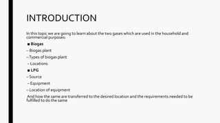
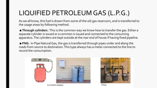
Biogas is produced from organic materials in a biogas plant and transported via pipes to the desired location. There are three types of biogas plants. LPG comes from sources and is delivered via equipment like regulators and valves, which must be properly installed and located. Piping for gases must meet requirements for material, size, protection, supports and prohibitions to ensure safe installation.

![CYLINDER LOCATION
STATIONARY INSTALLATIONS
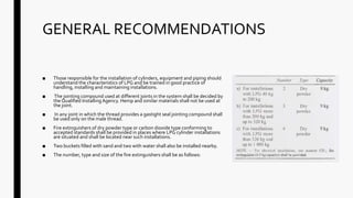
a) Stationary installation not exceeding 50 kg of LPG may be installed indoors on any floor.
b) Stationary installations each not exceeding 50 kg of LPG may be installed indoors on any floor and within the same workspace
provided the minimum distance between two such installations is 3 m, the proportion of such installations to floor area is one
installation per 5 m2 and the aggregate quantity' of gas of all such installations does not exceed 200 kg.
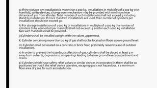
c) Stationary installation not exceeding 100 kg of LPG may be installed indoors on any floor provided the floor area for such an
installation is not less than 12 m2.
d) Stationary installations each not exceeding 100 kg of LPG may be installed indoors on any floor and within the same
workspace provided the minimum distance between two such installations is 3 m, the proportion of such installations to floor
area is one installation per 12 m2 and the aggregate quantity of gas of all such installations does not exceed 200 kg.
e) Stationary installation not exceeding 400 kg of LPG may be installed indoors in an enclosed section of a building or a room
reserved exclusively for this purpose and ventilated at low level directly to the outside air.
f) Stationary installations above 400 kg [200 kg in case provision as in (e) is not possible] but not exceeding 1 000 kg shall be
installed outdoors on ground floor level only. A minimum distance of 3 m shall be maintained between an installation and any
building, public place, roadways, and other surroundings.The installation shall be protected from excessive weathering by sun,
rain, etc., and from tampering by unauthorized persons. A lean-to roof with expanded metal on angle-iron framework on the
sides is considered suitable for this purpose. In any case, adequate ventilation at ground level to the outside air shall be provided.](https://image.slidesharecdn.com/gasandlpginstallation-180522173152/85/Gas-Installation-32-320.jpg)