Downloaded 540 times
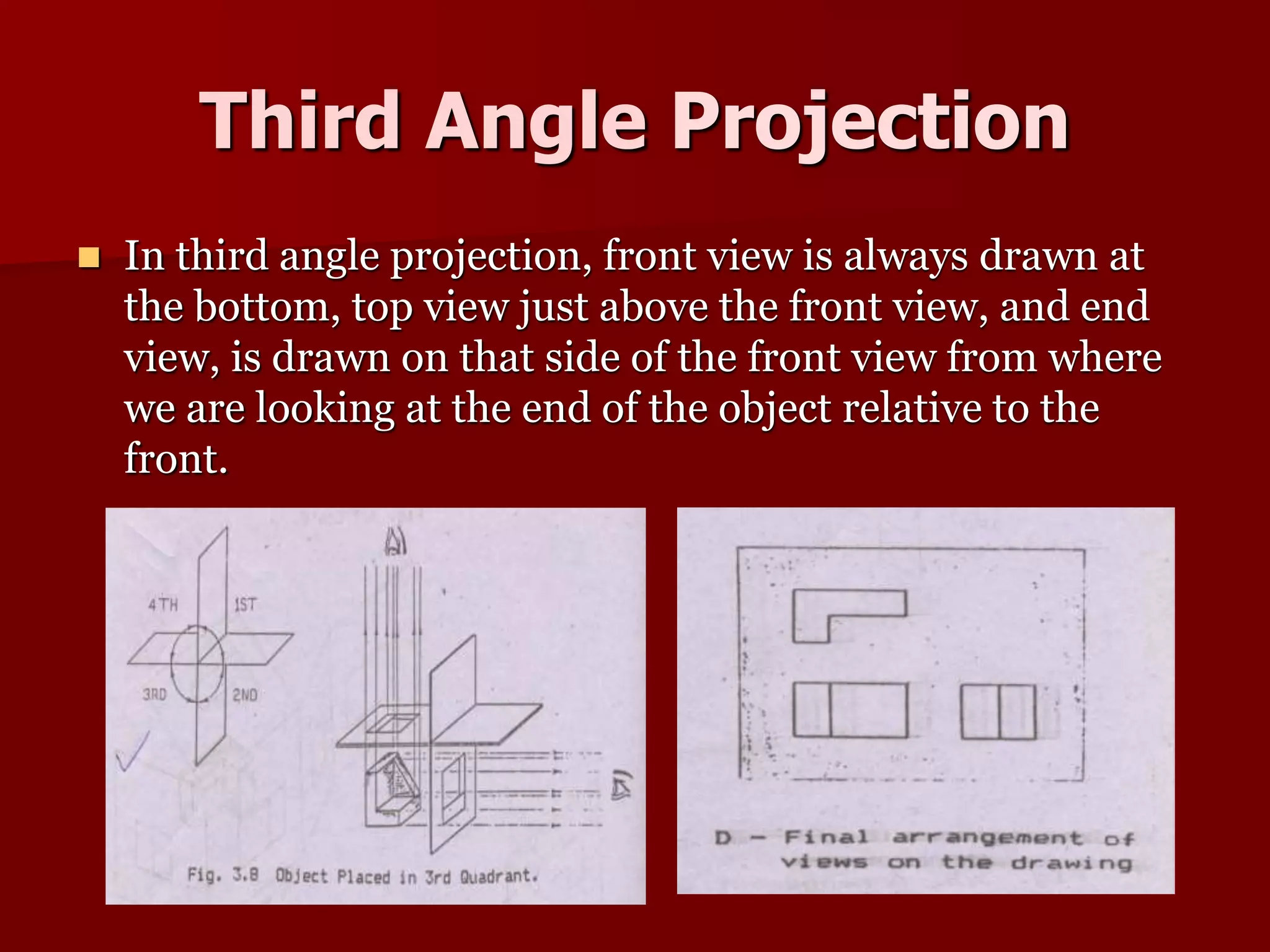
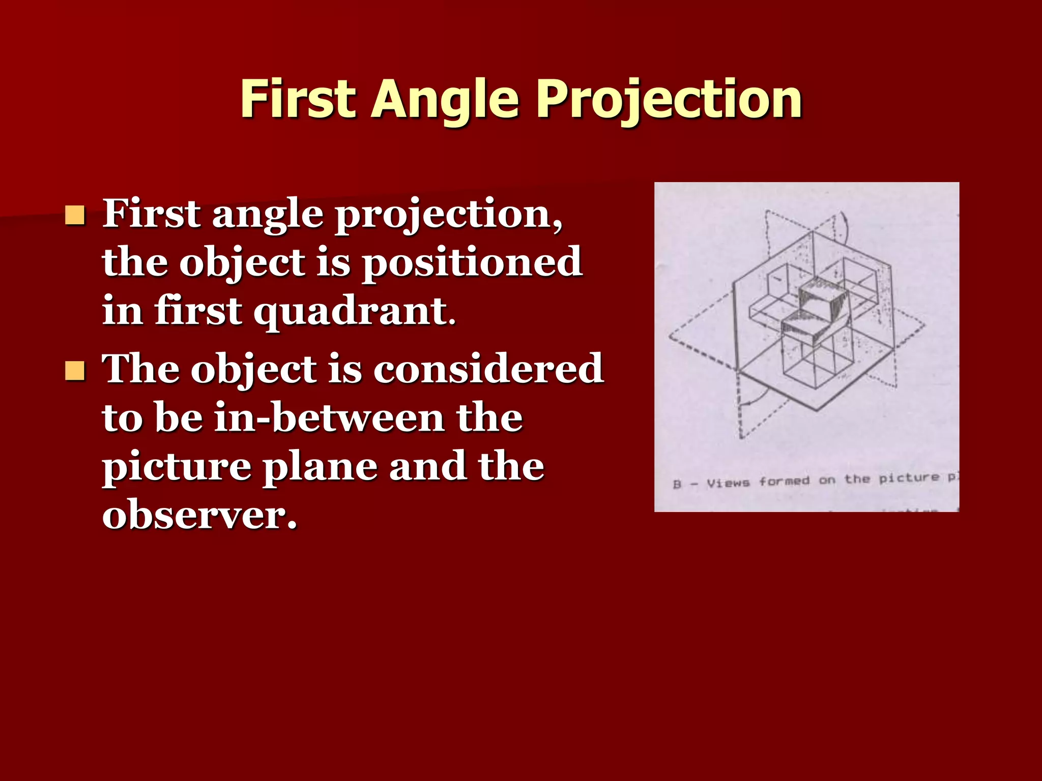
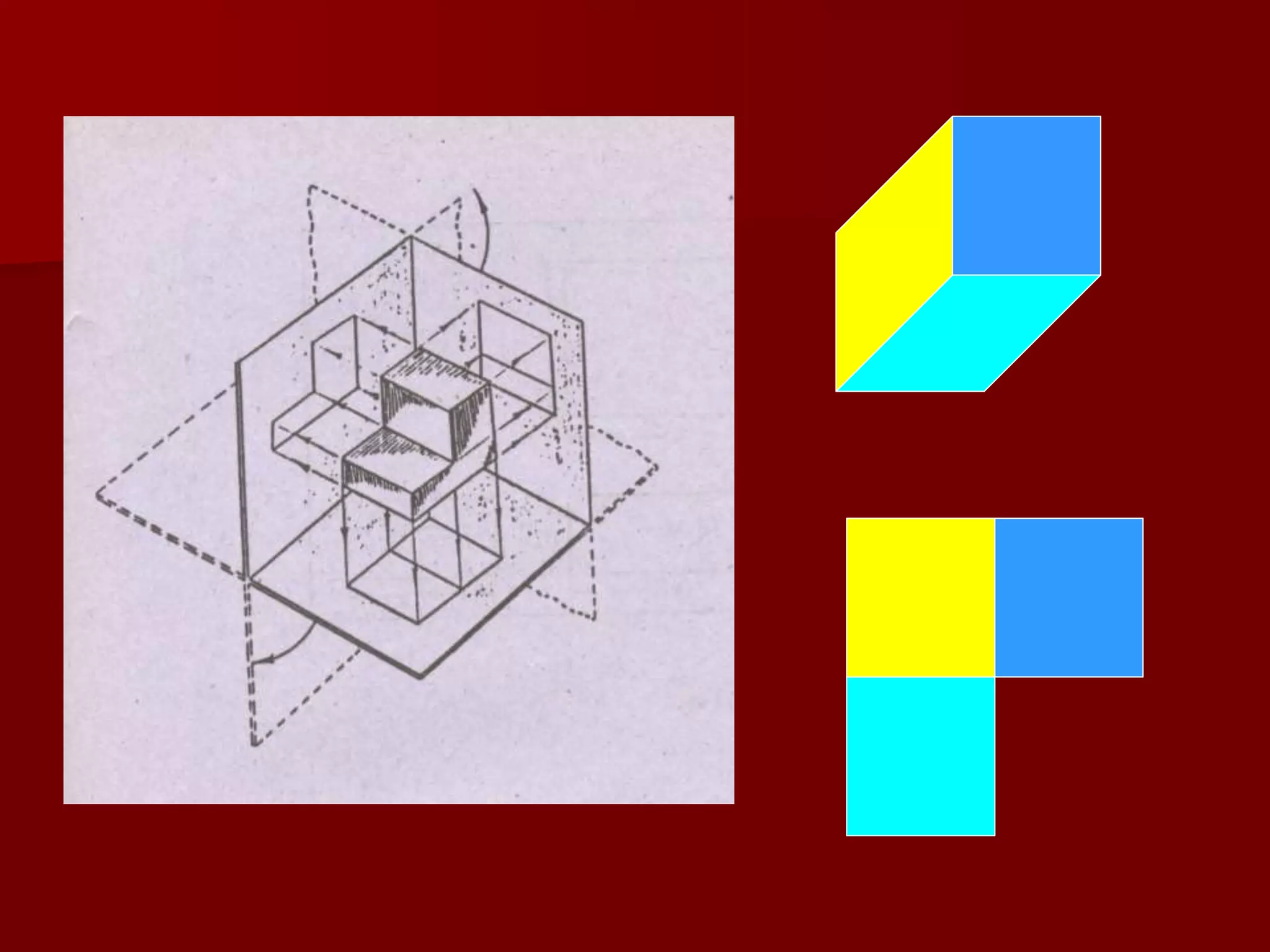
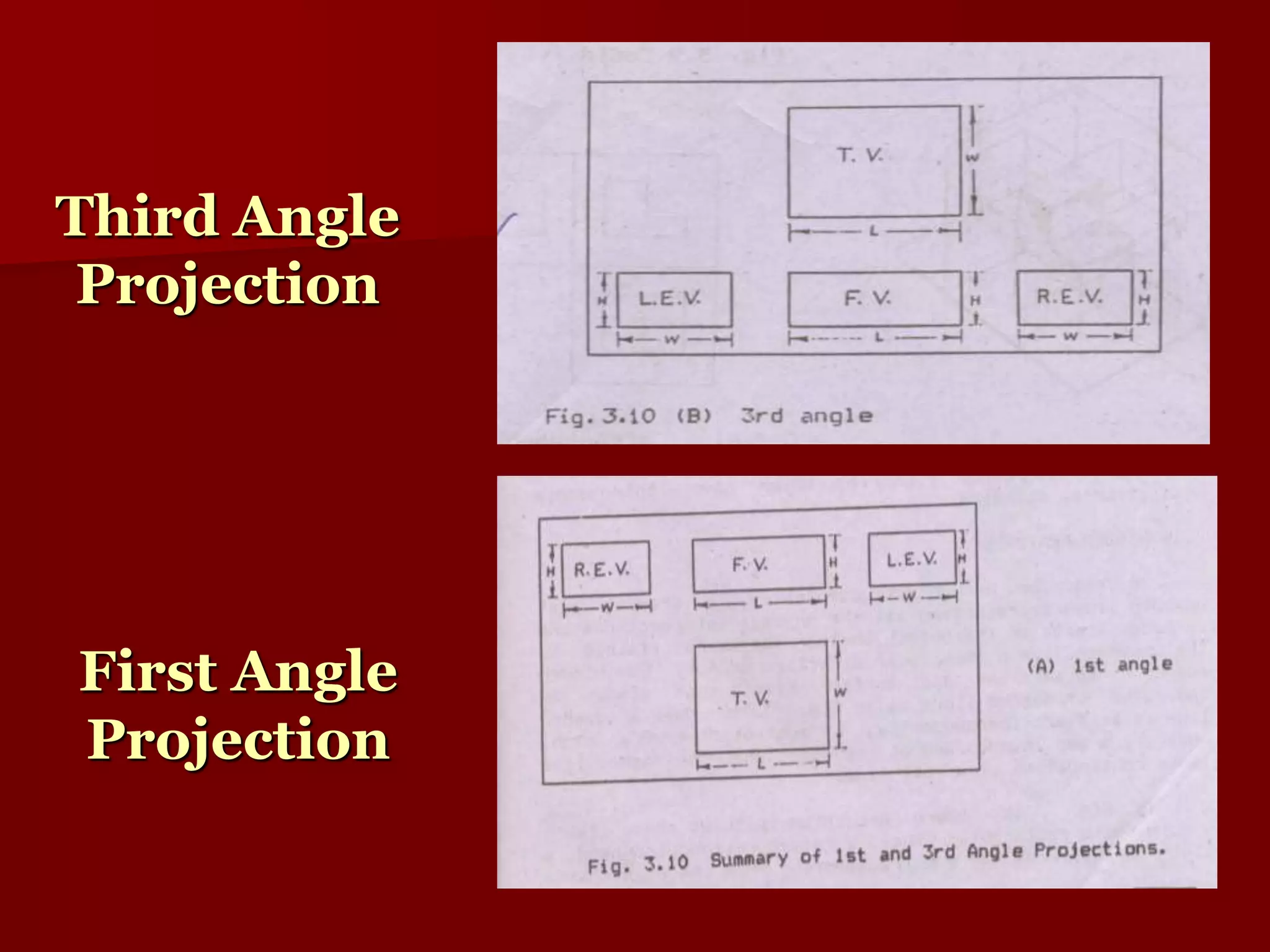
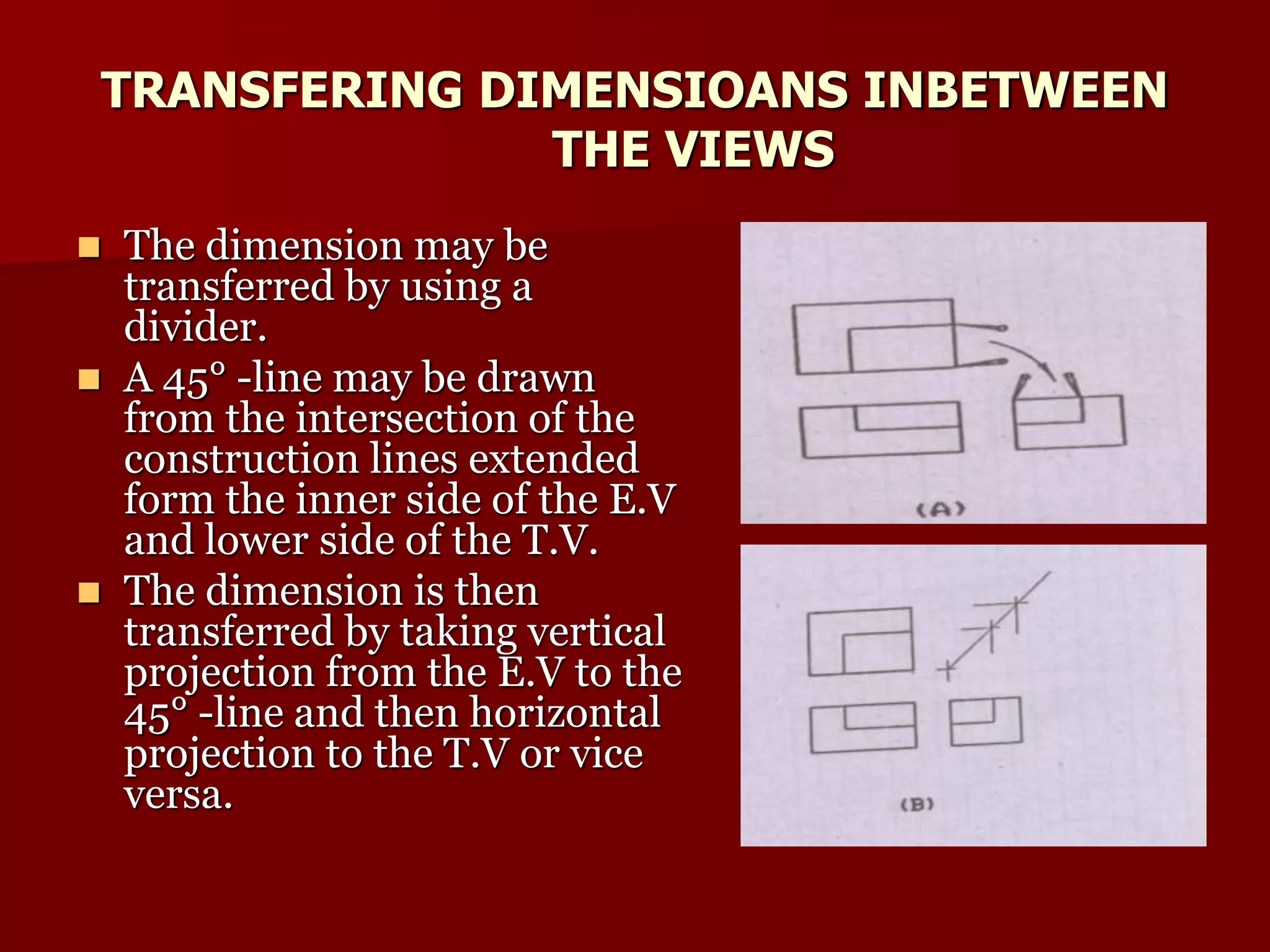
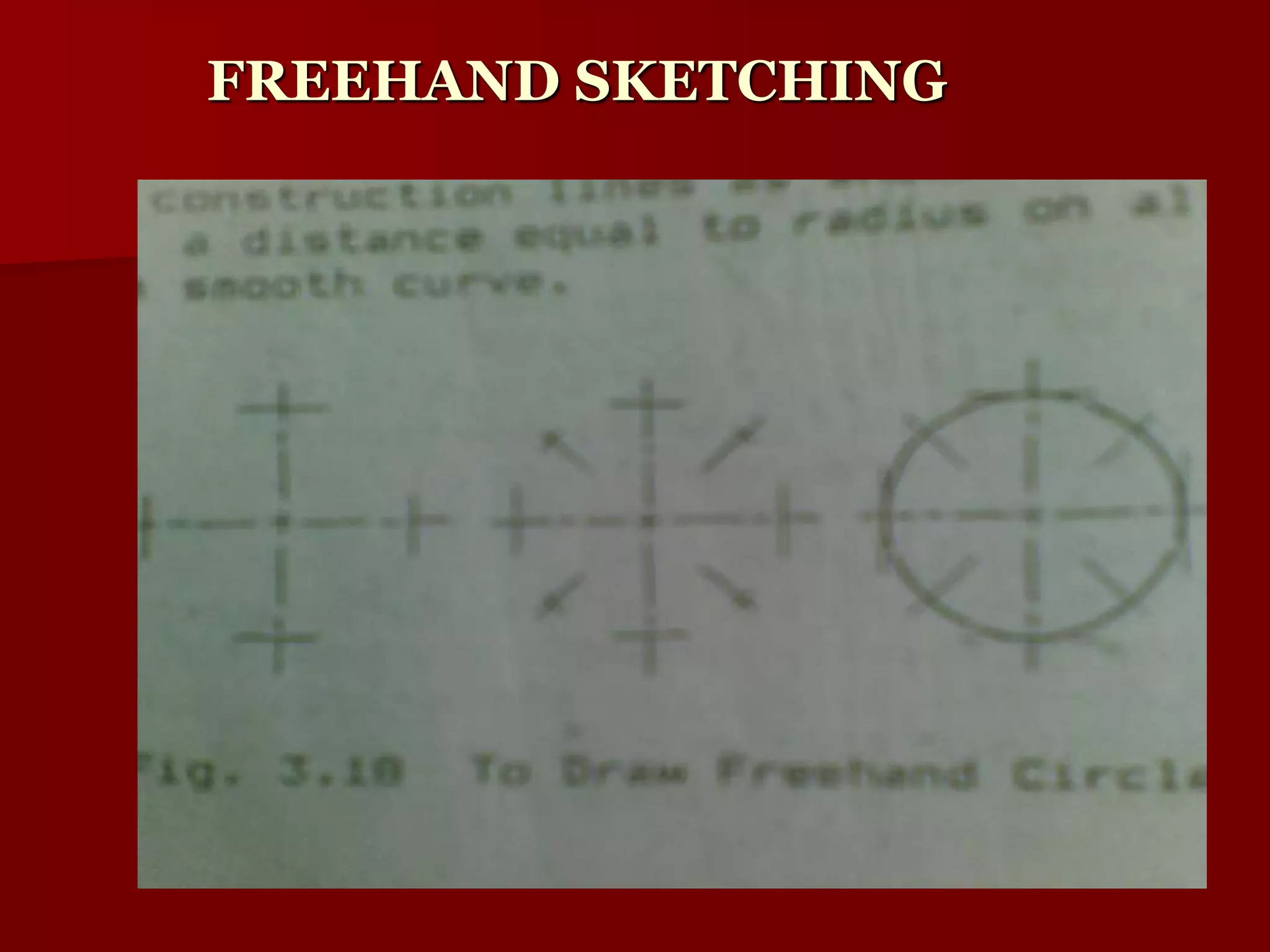


The document discusses different types of technical drawings used in civil engineering. It describes third angle and first angle projections, which differ in how top, front and side views of an object are arranged relative to each other on a page. It also covers conventions for indicating hidden lines, center lines, and the order drawings should be made. Dimensioning techniques like transferring measurements between views are explained. The document concludes by briefly discussing freehand sketching and physical modeling.