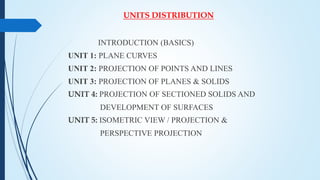
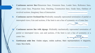
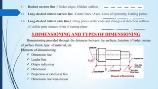
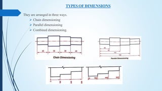
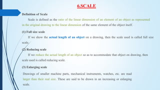
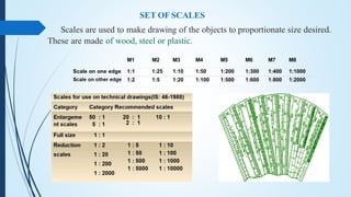
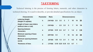
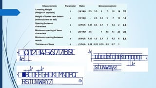
Quality defects in TMT Bars, Possible causes and Potential Solutions.
Engineering Graphics - Introduction PPT
1. ERODE SENGUNTHAR ENGINEERING COLLEGE
(An Autonomous Institution)
(Approved by AICTE, New Delhi, Permanently Affiliated to Anna University, Chennai&
Accredited by National Board of Accreditation (NBA), New Delhi,
National Accreditation Assessment Council, Bangalore)
PERUNDURAI, ERODE - 638 057
DEPARTMENT OF MECHANICAL ENGINEERING
Presented by,
Dr.J.BALAJI., M.E., Ph.D
Associate Professor
Department of Mechanical Engineering
Erode Sengunthar Engineering College
Perundurai, Erode 638051.
2. COURSE INTRODUCTION
19ES106 - ENGINEERING GRAPHICS
Course Objective(s):
The purpose of learning this course is:
To learn conventions and use of drawing tools
in making engineering drawings.
To draw orthographic projection of points and
lines.
To draw the projection of planes and simple
solids.
To draw the section of solids and obtain the
development of surfaces of given solids.
To draw the isometric projection of the given
solids.
Course Outcome(s):
At the end of this course, learners will be able to:
Recognize the conventions and apply construct
basic engineering curves.
Draw the orthographic projection of points and
lines.
Draw the projection of planes and simple solids.
Draw the section of solid drawings and
development of surfaces of given solids.
Draw the isometric projection of the given objects.
3. UNITS DISTRIBUTION
INTRODUCTION (BASICS)
UNIT 1: PLANE CURVES
UNIT 2: PROJECTION OF POINTS AND LINES
UNIT 3: PROJECTION OF PLANES & SOLIDS
UNIT 4: PROJECTION OF SECTIONED SOLIDS AND
DEVELOPMENT OF SURFACES
UNIT 5: ISOMETRIC VIEW / PROJECTION &
PERSPECTIVE PROJECTION
4. INTRODUCTION (BASICS)
SYNOPSIS
1. DEFINITION OF ENGINEERING GRAPHICS
2. DRAFTING TOOLS
3. DRAWING SHEETS AND ITS SIZE
4. TYPES OF LINES
5. DIMENSIONING AND TYPES OF DIMENSIONING
6. SCALE
7. LETTERING
5. 1.DEFINITION OF ENGINEERING GRAPHICS
Engineering graphics is the language for Effective Communication among engineers
which elaborates the details of any component, structure or circuit at its initial drawing through
drawing.
2.DRAFTING TOOL
The following are the various drafting tools used in engineering graphics
8. 4.TYPES OF LINES
i. Continuous narrow Lines
ii. Continuous wide lines
iii. Continuous Narrow Lines With Zigzags
iv. Dashed Narrow Lines
v. Long-Dashed Dotted Narrow Lines
vi. long-dashed dotted narrow line
vii. Continuous wide lines
9. i. Continuous narrow line-Dimension lines, Extension lines, Leader lines, Reference lines,
Short center lines, Projection lines, Hatching, Construction lines, Guide lines, Outlines of
revolved sections ,Imaginary lines of intersection
ii. Continuous narrow freehand line-Preferably manually represented termination of partial or
interrupted views, Cuts and sections, if the limit is not a line of symmetry or a Centre line·
iii. Continuous narrow line with zigzags -Preferably mechanically represented termination of
partial or interrupted views. cuts and sections, if the limit is not a line of symmetry or a
center line .
iv. Continuous wide line -Visible edges, visible outlines, Main representations in diagrams,
maps. flow charts.
10. 5.DIMENSIONING AND TYPES OF DIMENSIONING
v. Dashed narrow line -Hidden edges ,Hidden outlines
vi. Long-dashed dotted narrow line -Centre lines / Axes. Lines of symmetry, Cutting planes
vii. Long-dashed dotted wide line-Cutting planes at the ends and changes of direction outlines
of visible parts situated front of cutting plane
Dimensioning provided through the distances between the surfaces, location of holes, nature
of surface finish, type of material, etc.
Elements of dimensioning
Dimension line
Leader line
Origin indication
Dimension
Projection or extension line
Dimension line termination
11. TYPES OF DIMENSIONS
They are arranged in three ways.
Chain dimensioning
Parallel dimensioning
Combined dimensioning.
12. 6.SCALE
Definition of Scale
Scale is defined as the ratio of the linear dimension of an element of an object as represented
in the original drawing to the linear dimension of the same element of the object itself.
(1) Full size scale
If we show the actual length of an object on a drawing, then the scale used is called full size
scale.
(2) Reducing scale
If we reduce the actual length of an object so as to accommodate that object on drawing, then
scale used is called reducing scale.
(3) Enlarging scale
Drawings of smaller machine parts, mechanical instruments, watches, etc. are mad
larger than their real size. These are said to be drawn in an increasing or enlarging
scale.
13. SET OF SCALES
Scales are used to make drawing of the objects to proportionate size desired.
These are made of wood, steel or plastic.
14. 7.LETTERING
Technical lettering is the process of forming letters, numerals, and other characters in
technical drawing. It is used to describe, or provide detailed specifications for, an object.