Downloaded 494 times


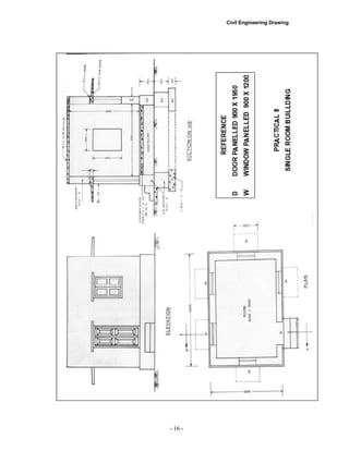
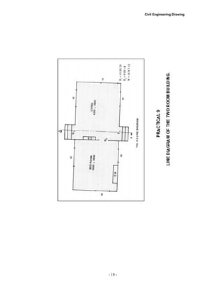
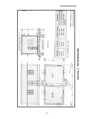
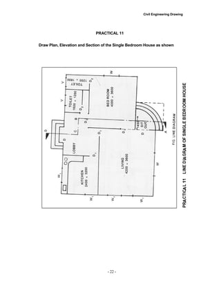
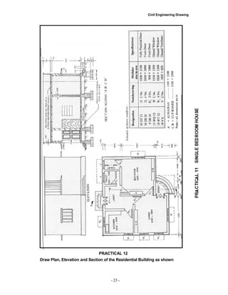
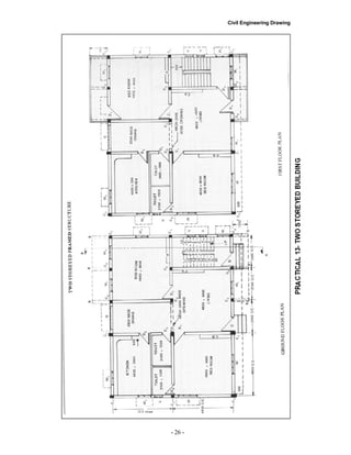
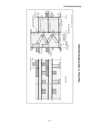

Here are the steps to develop the plan, section and front elevation of the one room building to a scale of 1:50 as per the given line diagram and specifications: 1. Draw the line diagram of the one room building on a drawing sheet. Mark the internal dimensions of the room. 2. For the plan: - Draw the outer lines of walls with a thickness of 400mm as per the line diagram and dimensions. - Draw the position of the door and window openings within the walls. - Mark all internal and external dimensions. 3. For the section: - Draw the foundation details as per the given specifications, showing the C.C bed, brick masonary footing and offsets.


![Air Barrier[1]](https://cdn.slidesharecdn.com/ss_thumbnails/airbarrier1-090422103337-phpapp02-thumbnail.jpg?width=640&height=640&fit=bounds)