Download as PDF, PPTX

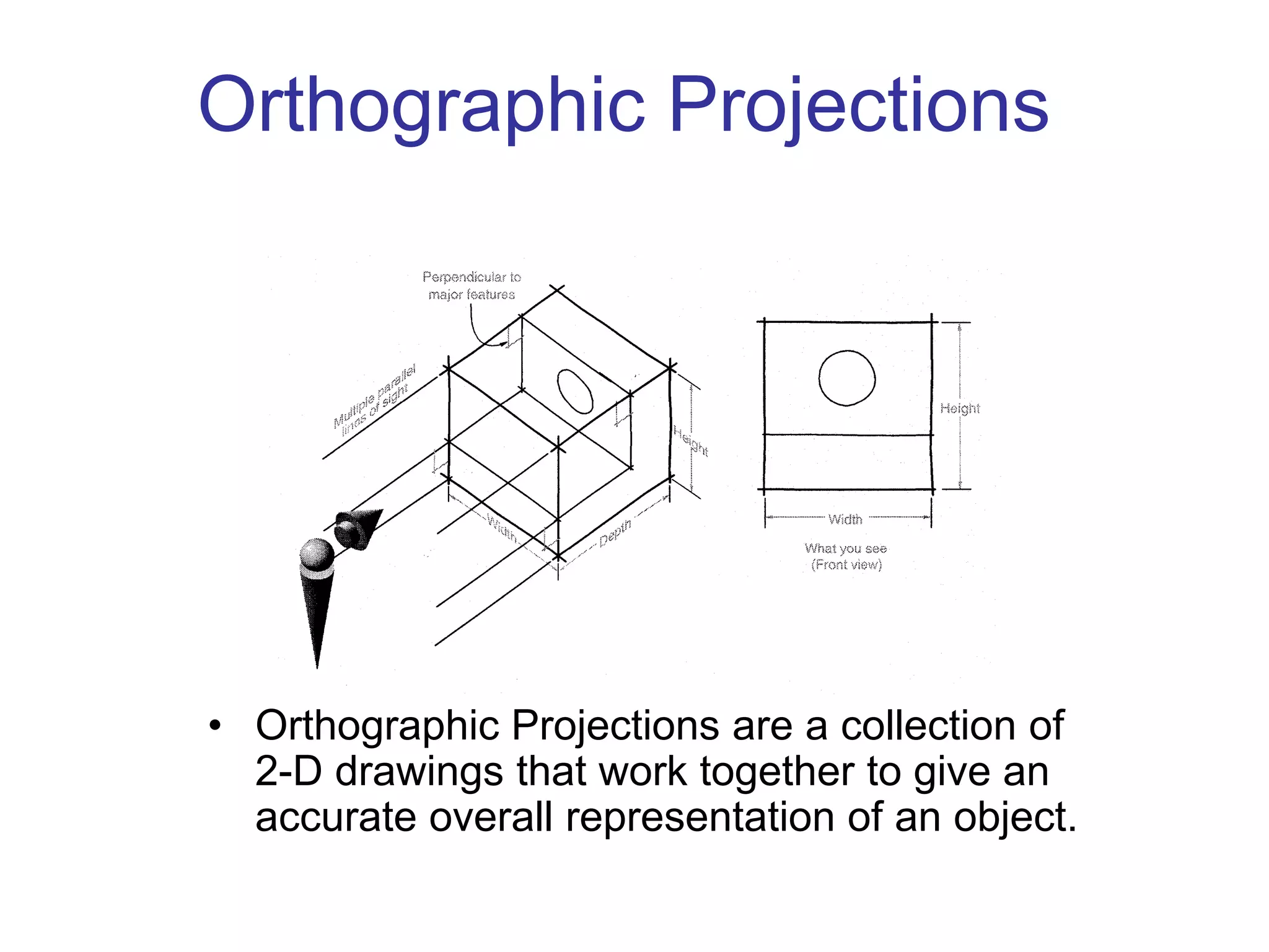


Orthographic projections are a collection of 2D drawings that together accurately represent an object. The six principal views or orthographic views are the front, top, side, and three quarter views. Guidelines for choosing views include selecting the most descriptive front view and using the longest dimension as width or depth. Orthographic projections place an object within an imaginary glass box and freeze views from each side, which are then unfolded. Dimensioning and tolerancing provide manufacturing specifications. Various line types, such as visible, hidden, and center lines, have precedence and are used to fully convey a drawing's geometry and features.