


The document discusses dimensioning techniques including: 1) Dimensioning components like extension lines, dimension lines, and dimension numbers and their proper usage. 2) Dimensioning common features like lengths, angles, arcs, holes, and their associated dimensioning methods. 3) Recommended practices for placement of dimensions and problem solving steps for dimensioning objects.
Introduction to dimensioning concepts and its components. Overview of features and recommended practices.
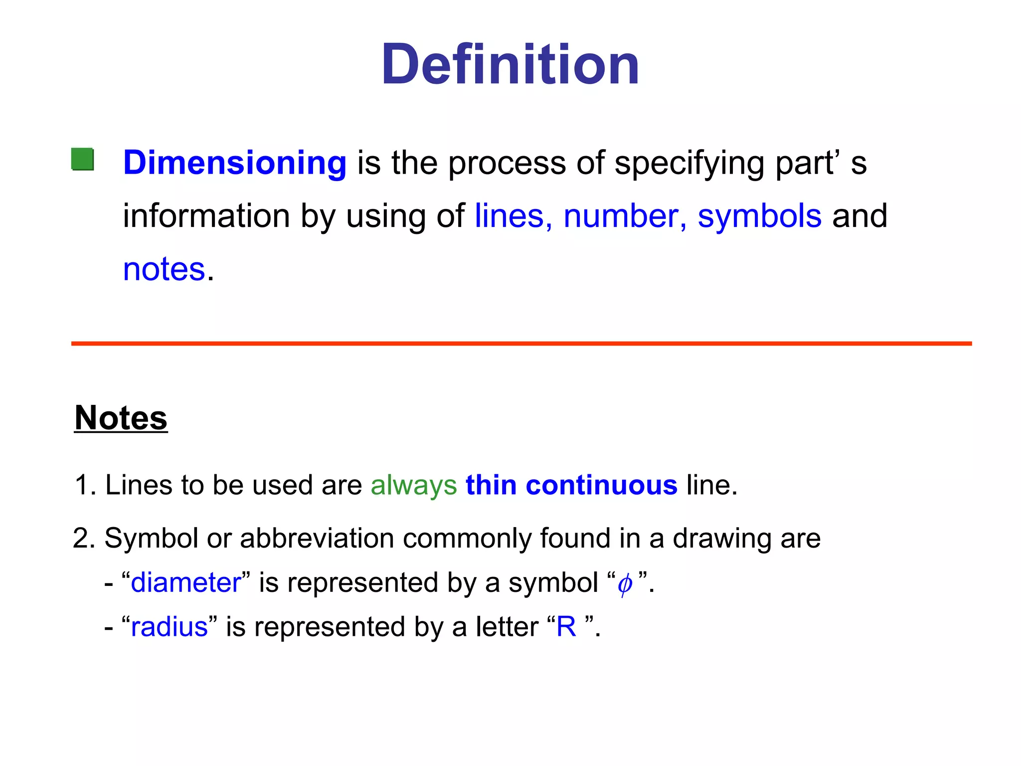
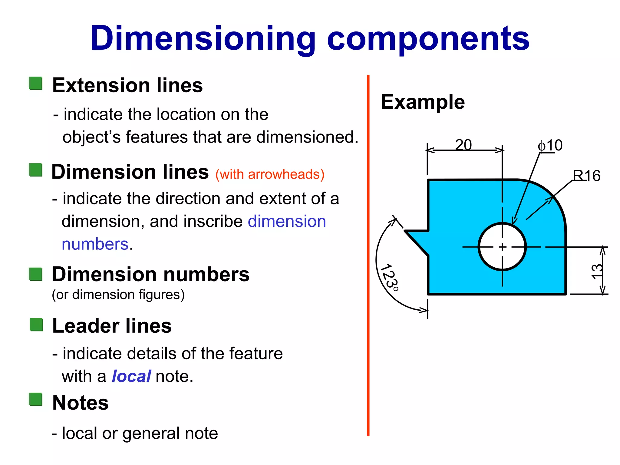
Dimensioning defined as specification of part information using lines, numbers, symbols, and notes.
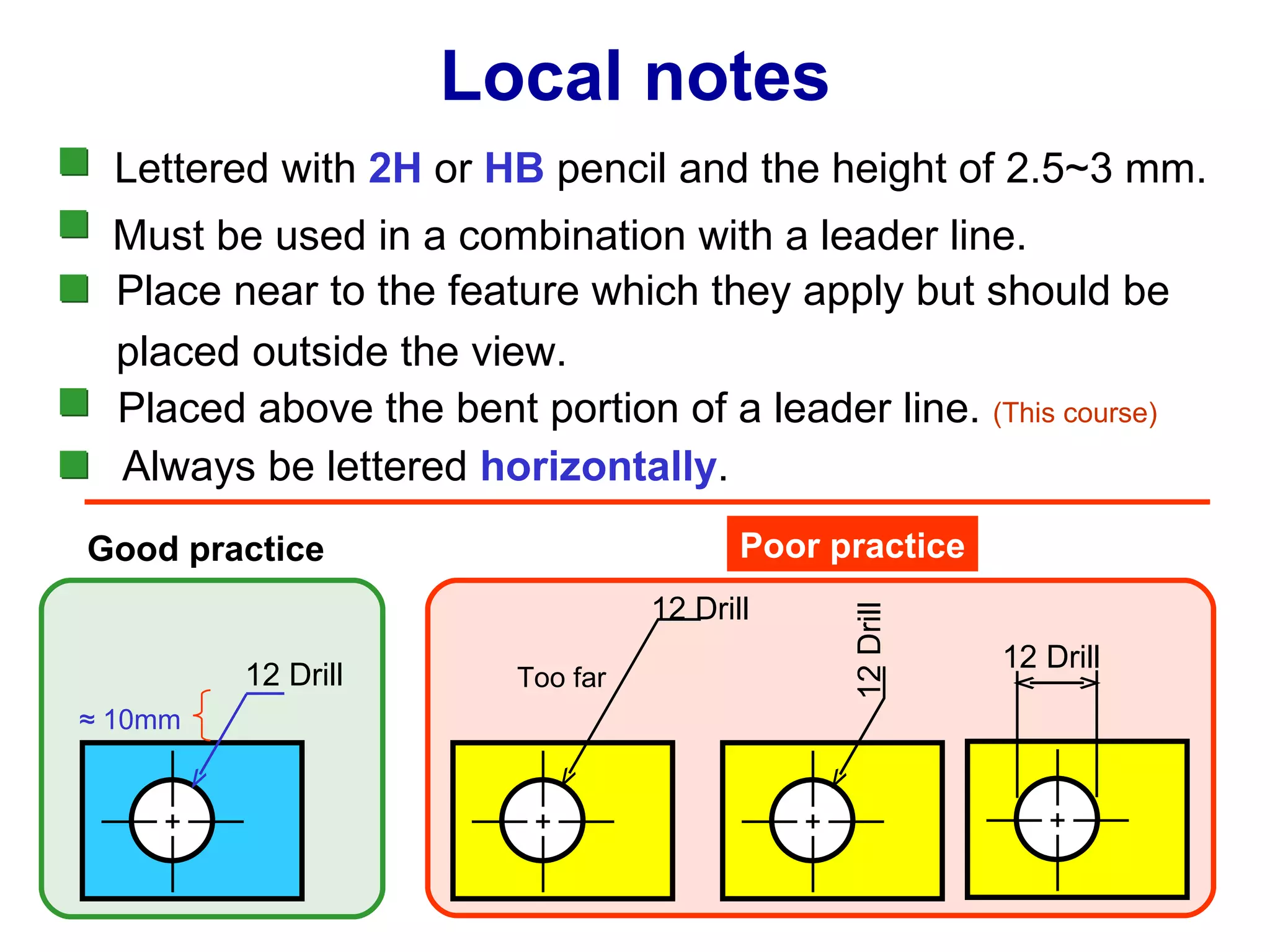
Summary of dimensioning components including extension lines, dimension lines, dimension numbers, and note application.
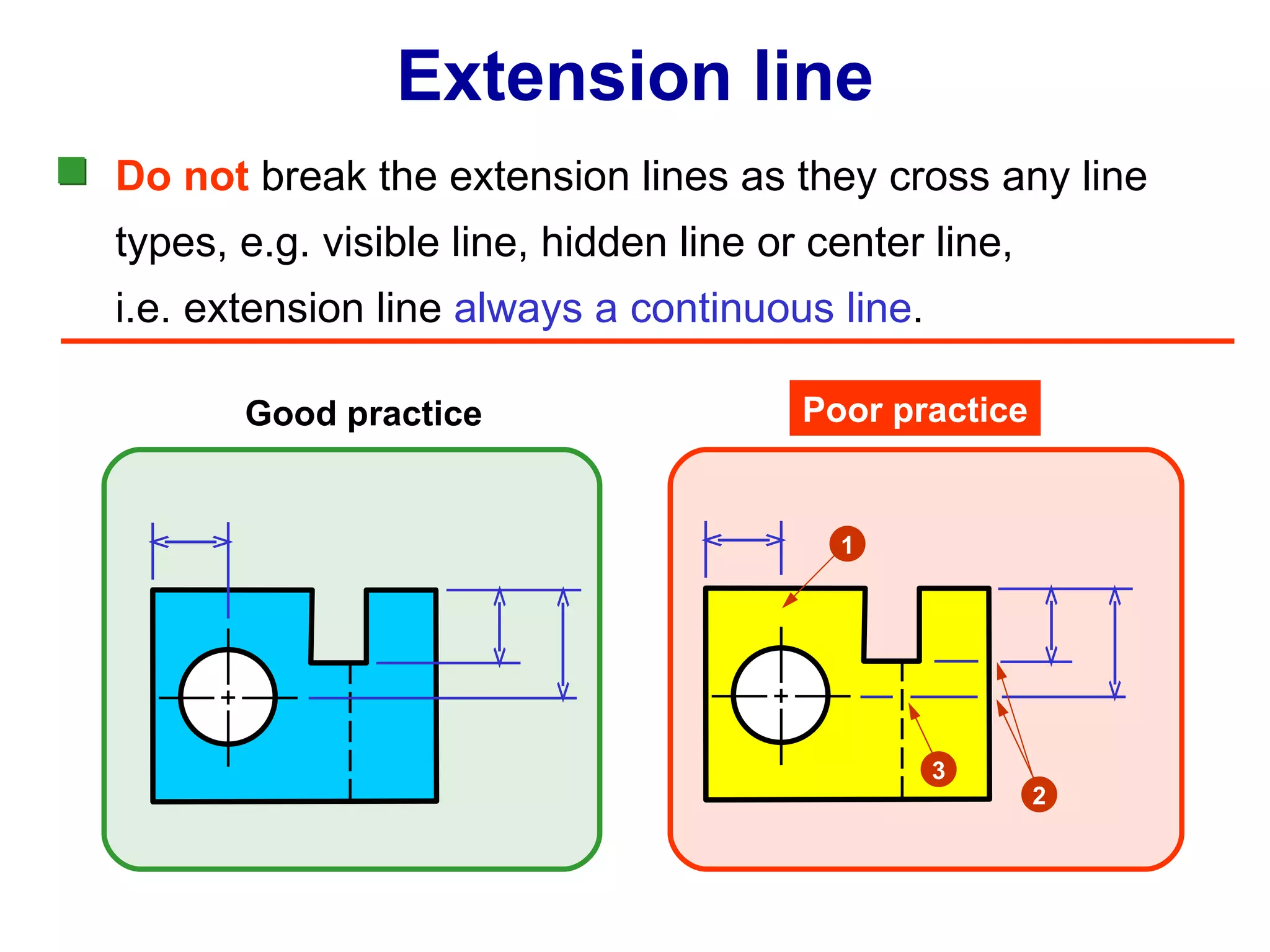
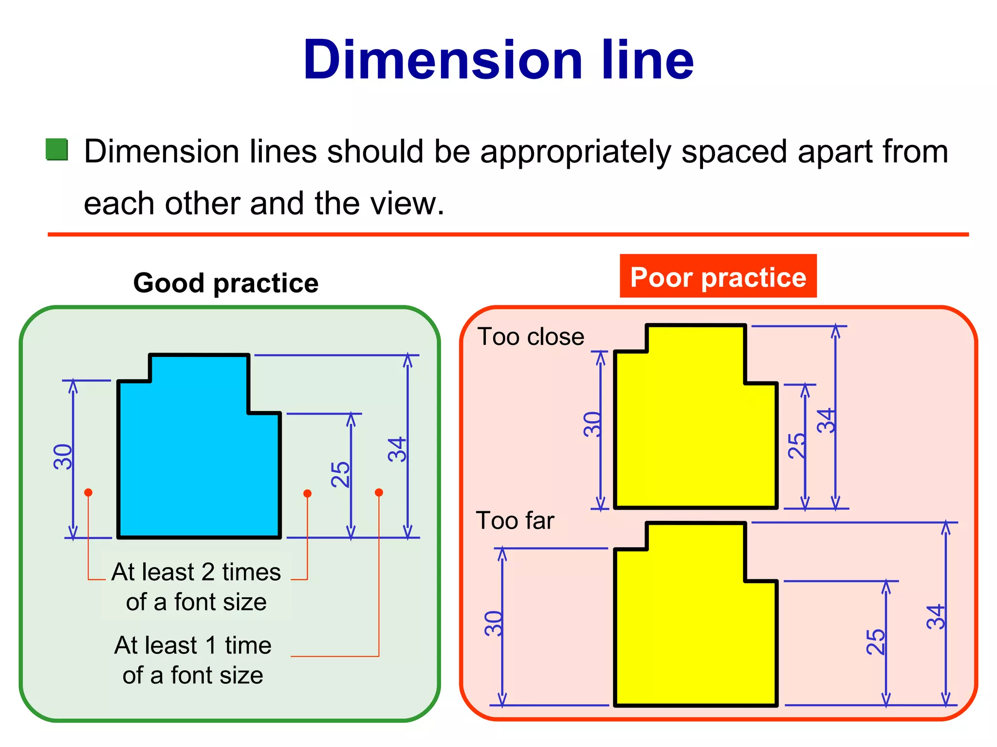
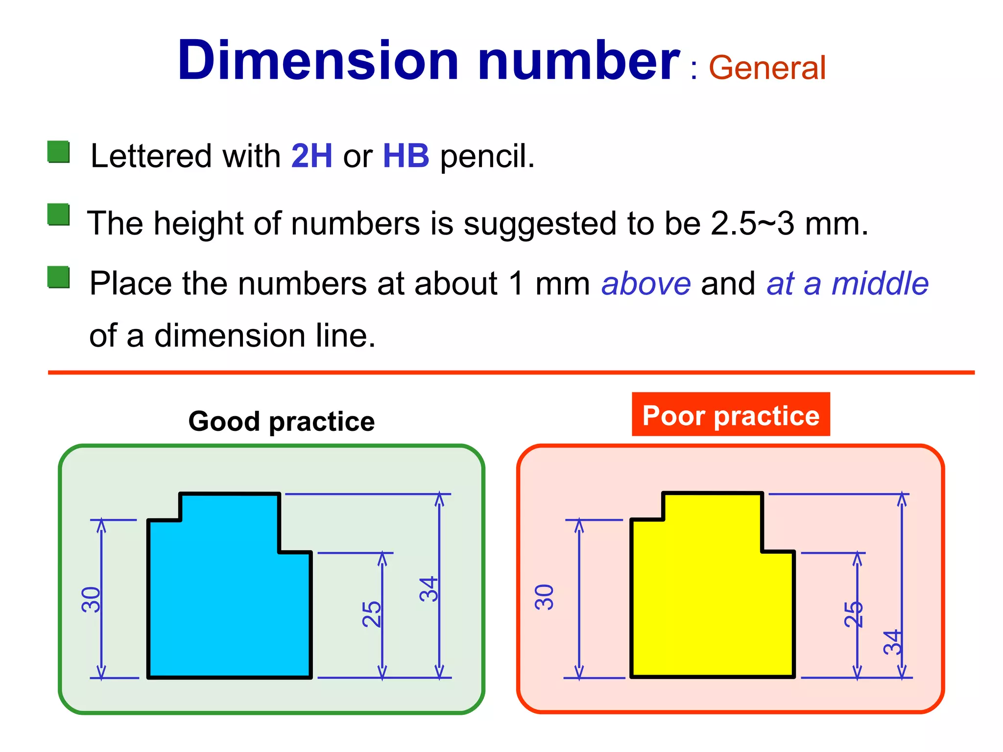
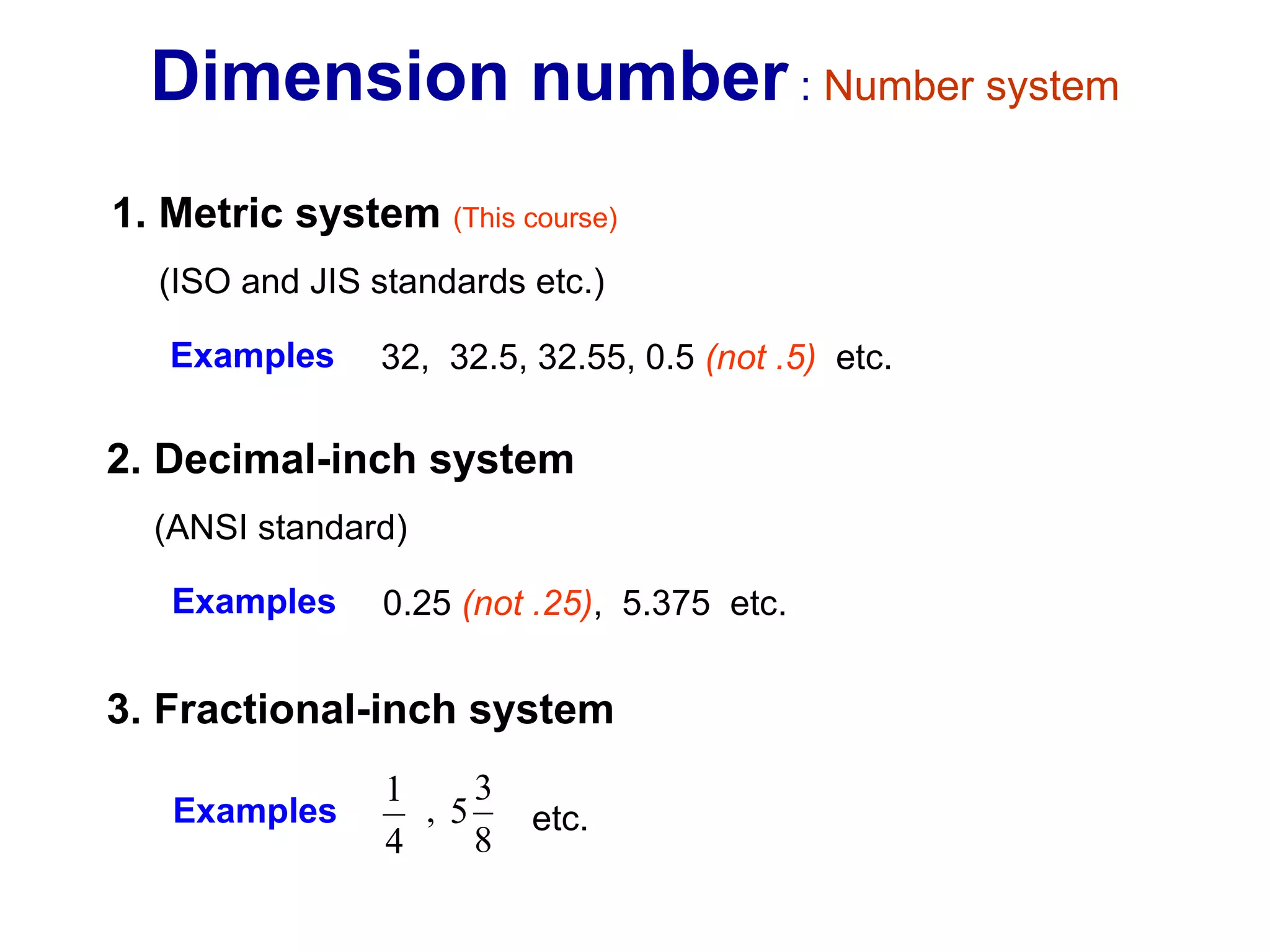
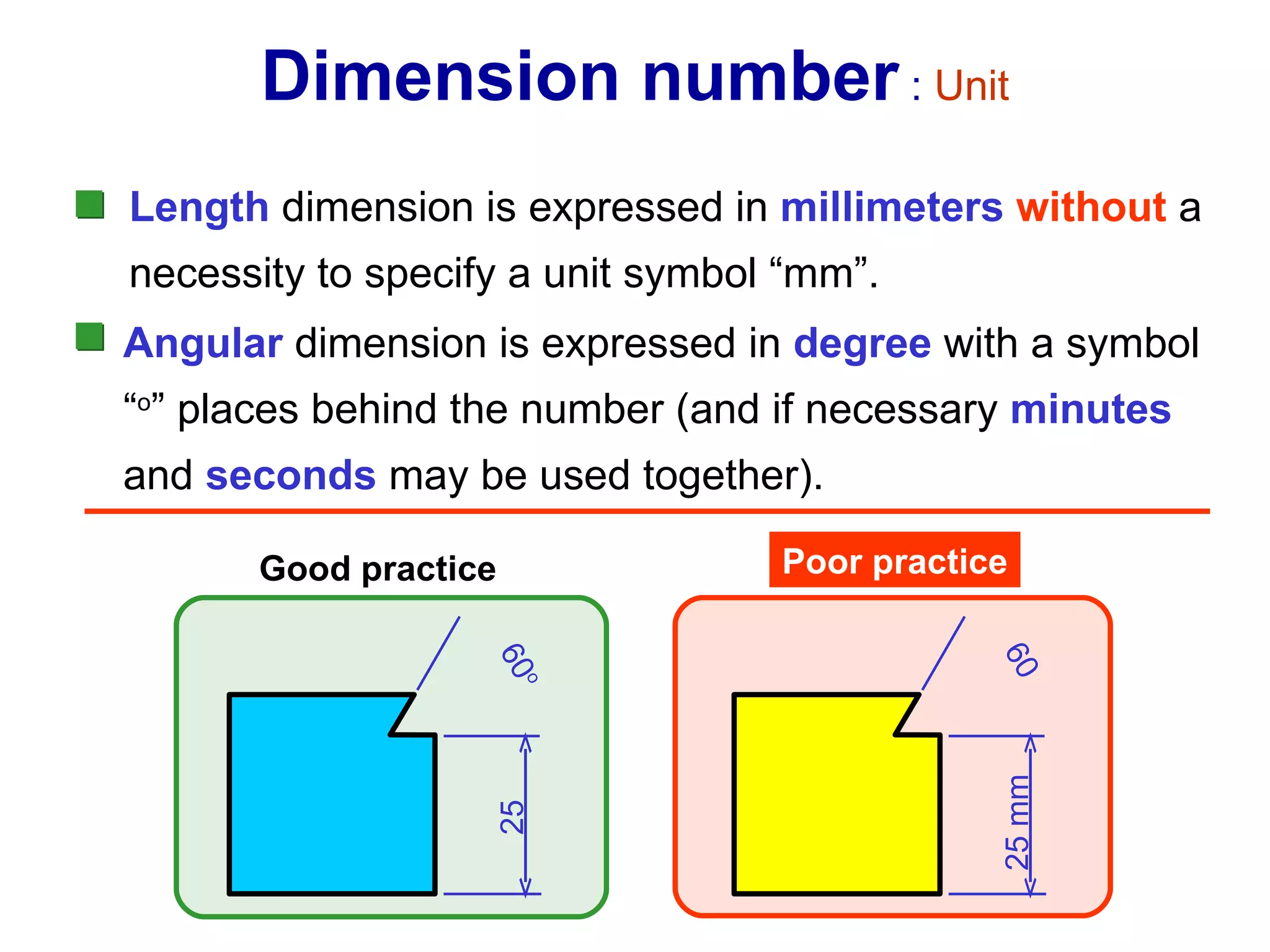
Best practices for extension and dimension lines, noting visibility, spacing, number systems, and unit orientations.
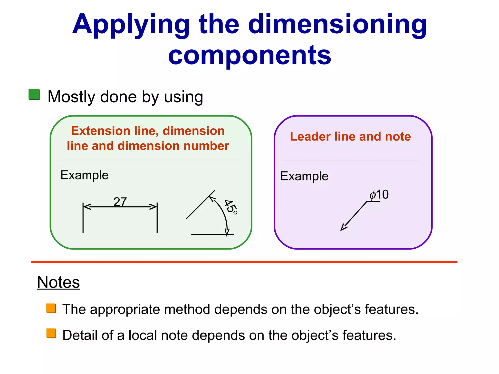
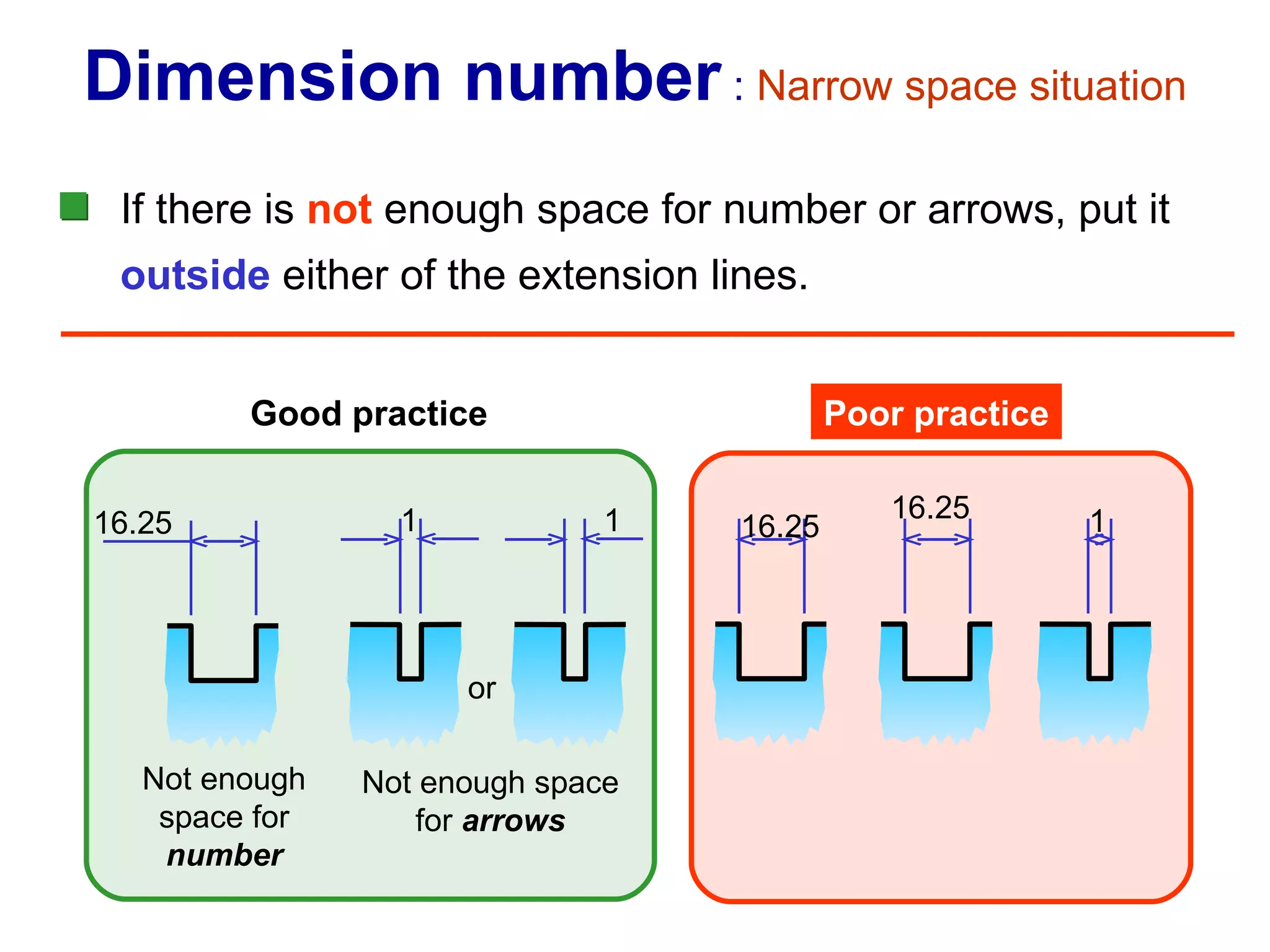
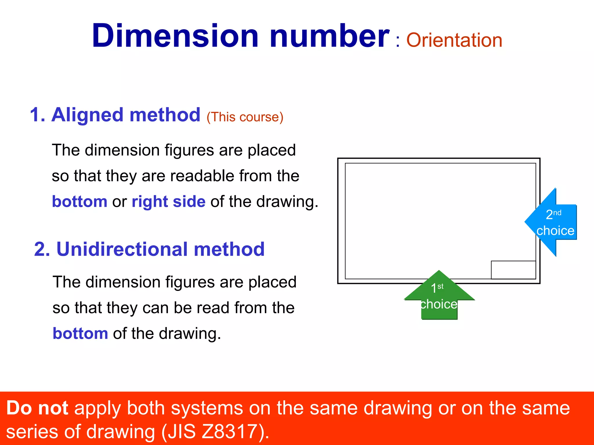
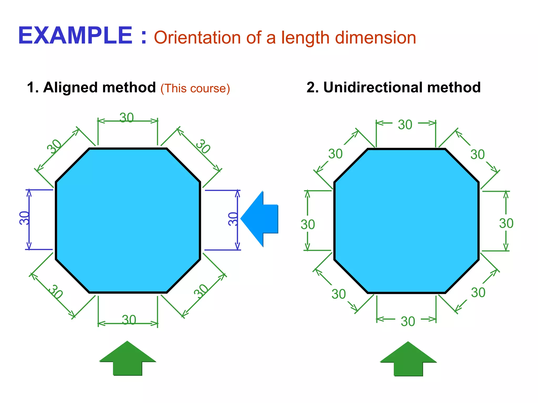
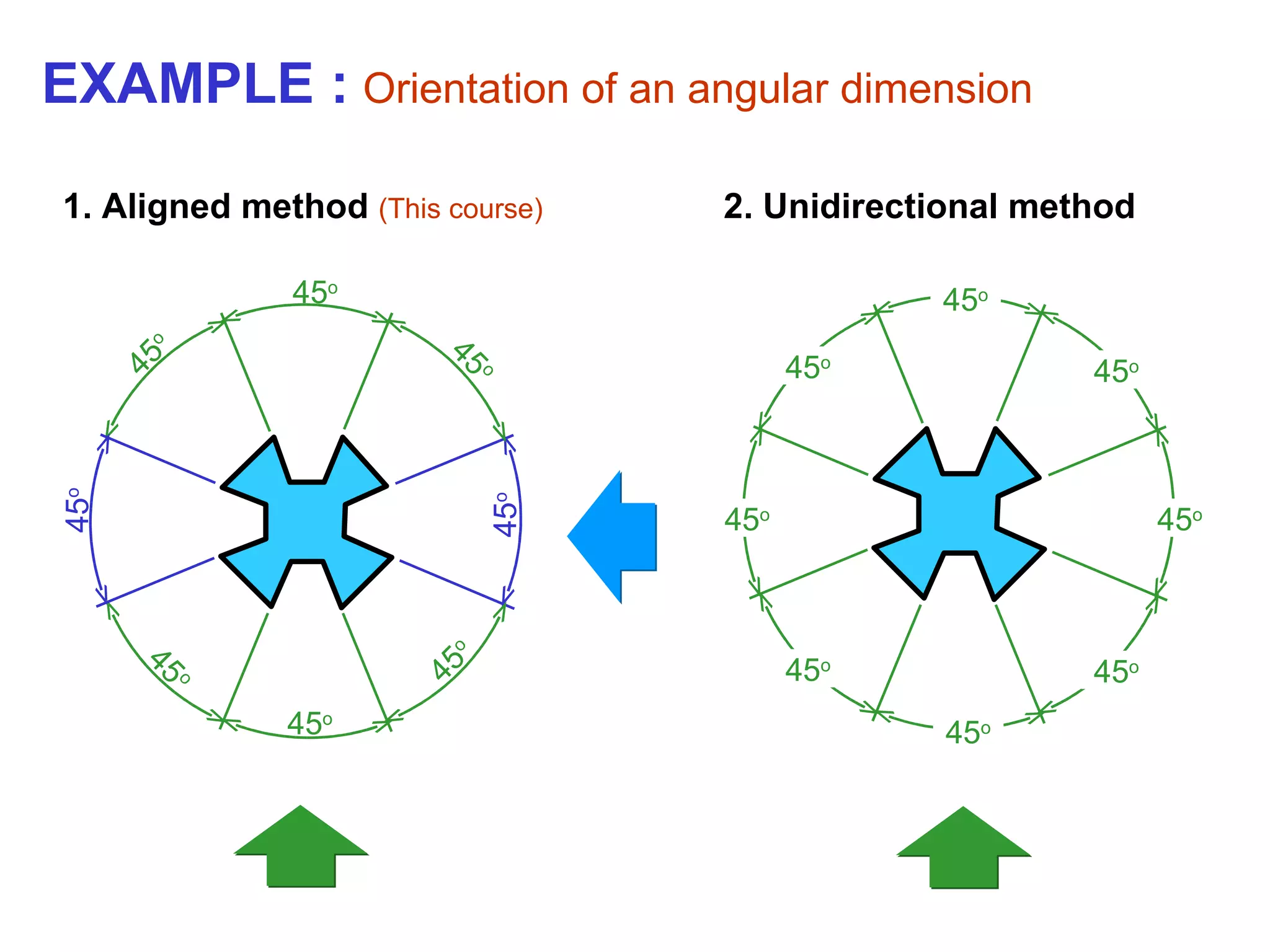
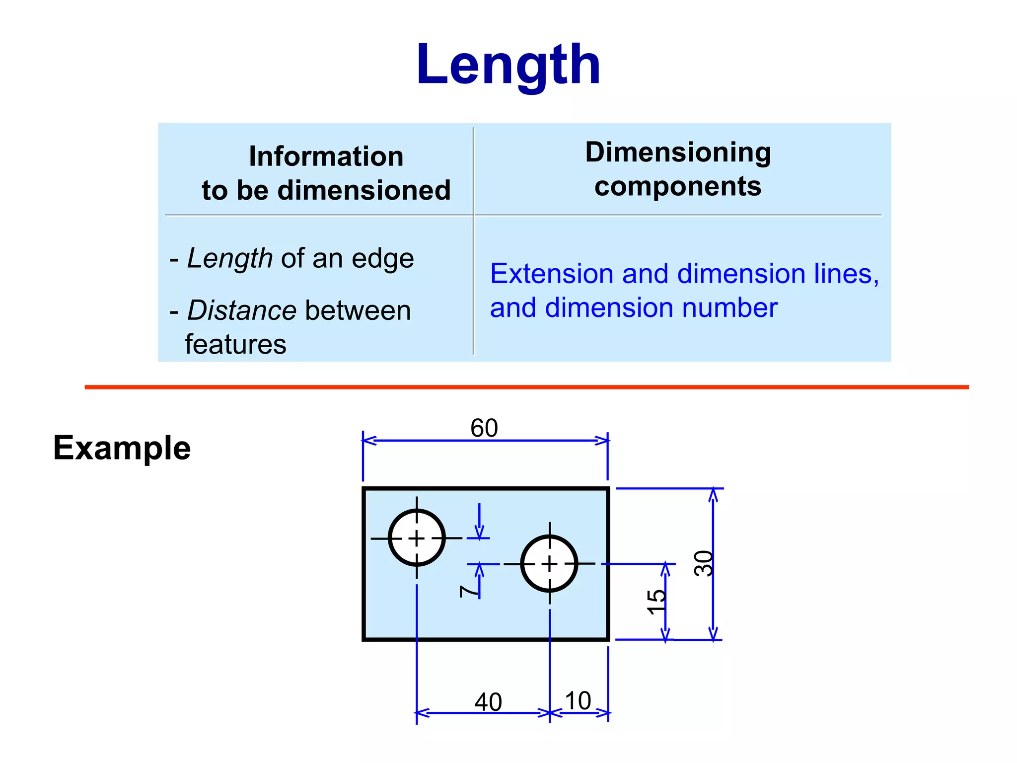
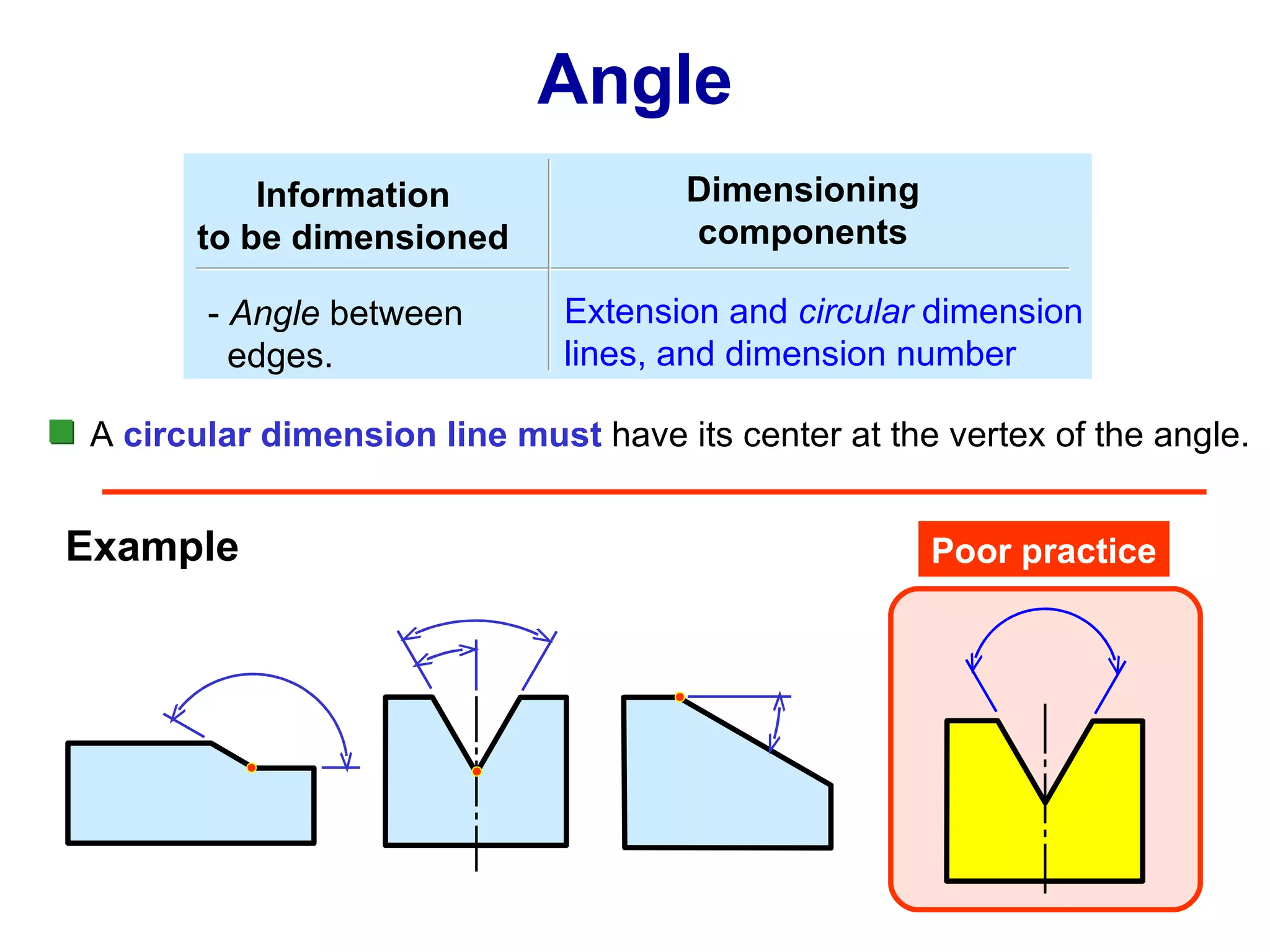
Instructions on representing angular and length dimensions, addressing space constraints and orientation methods.
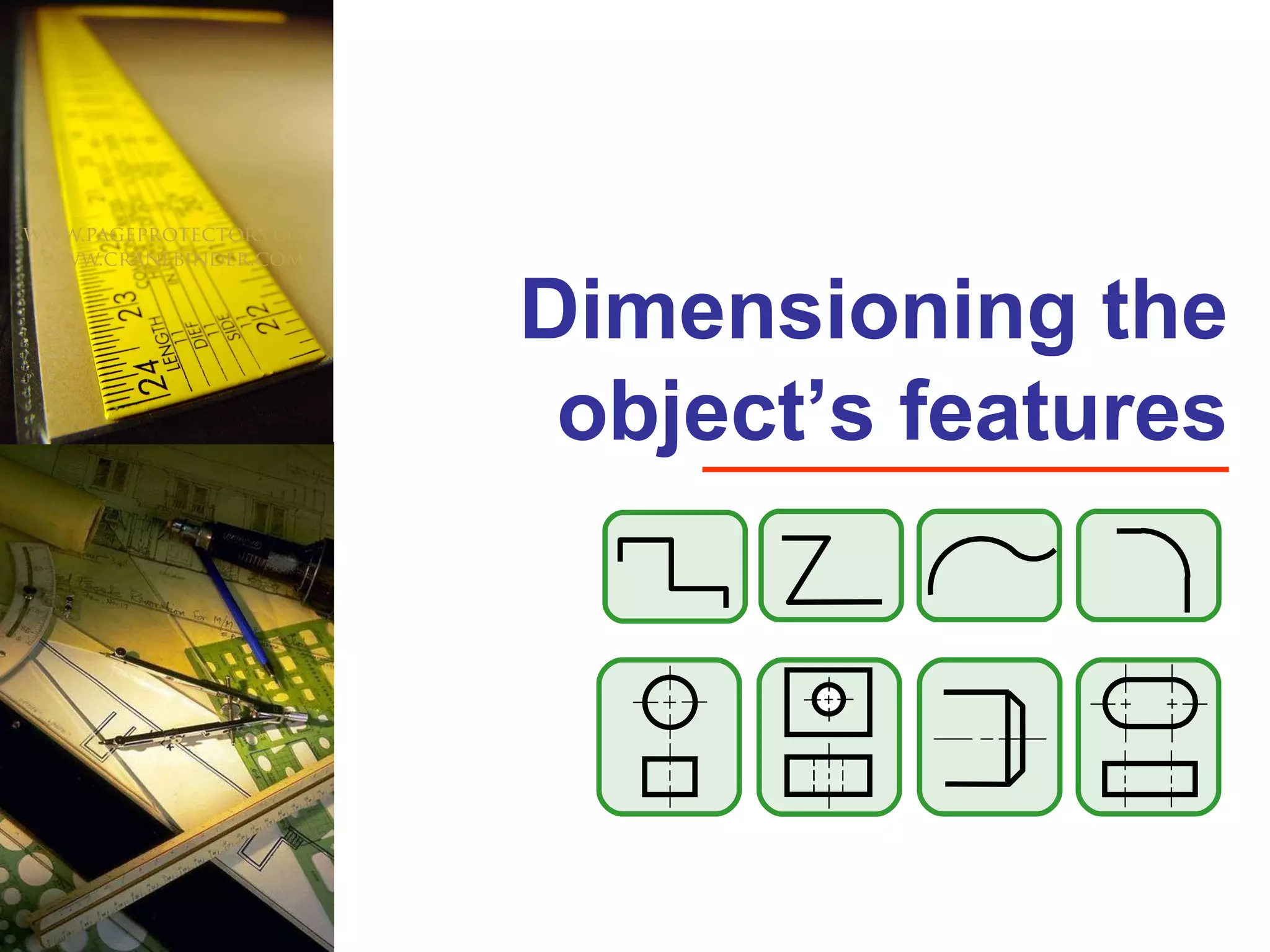
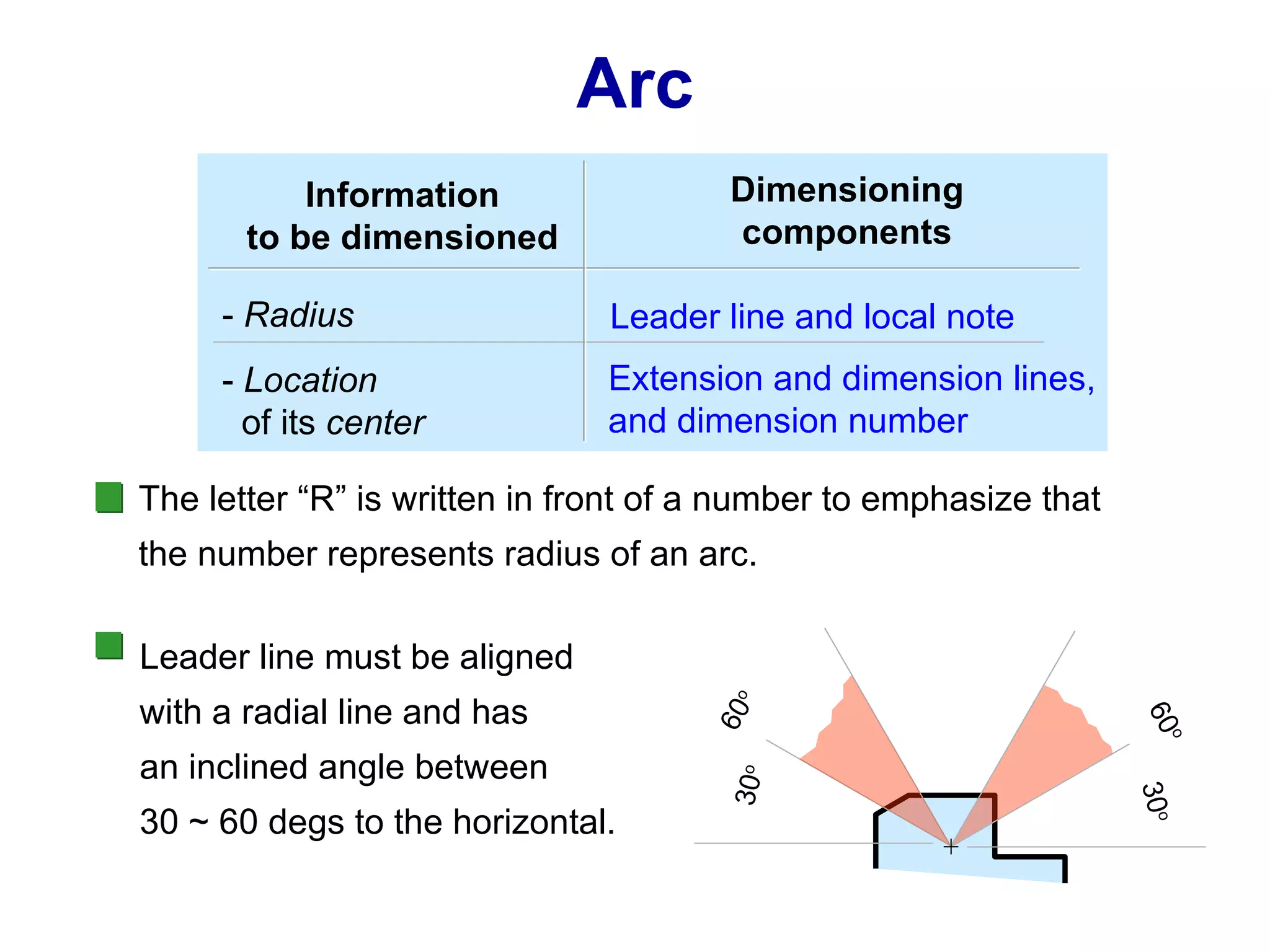
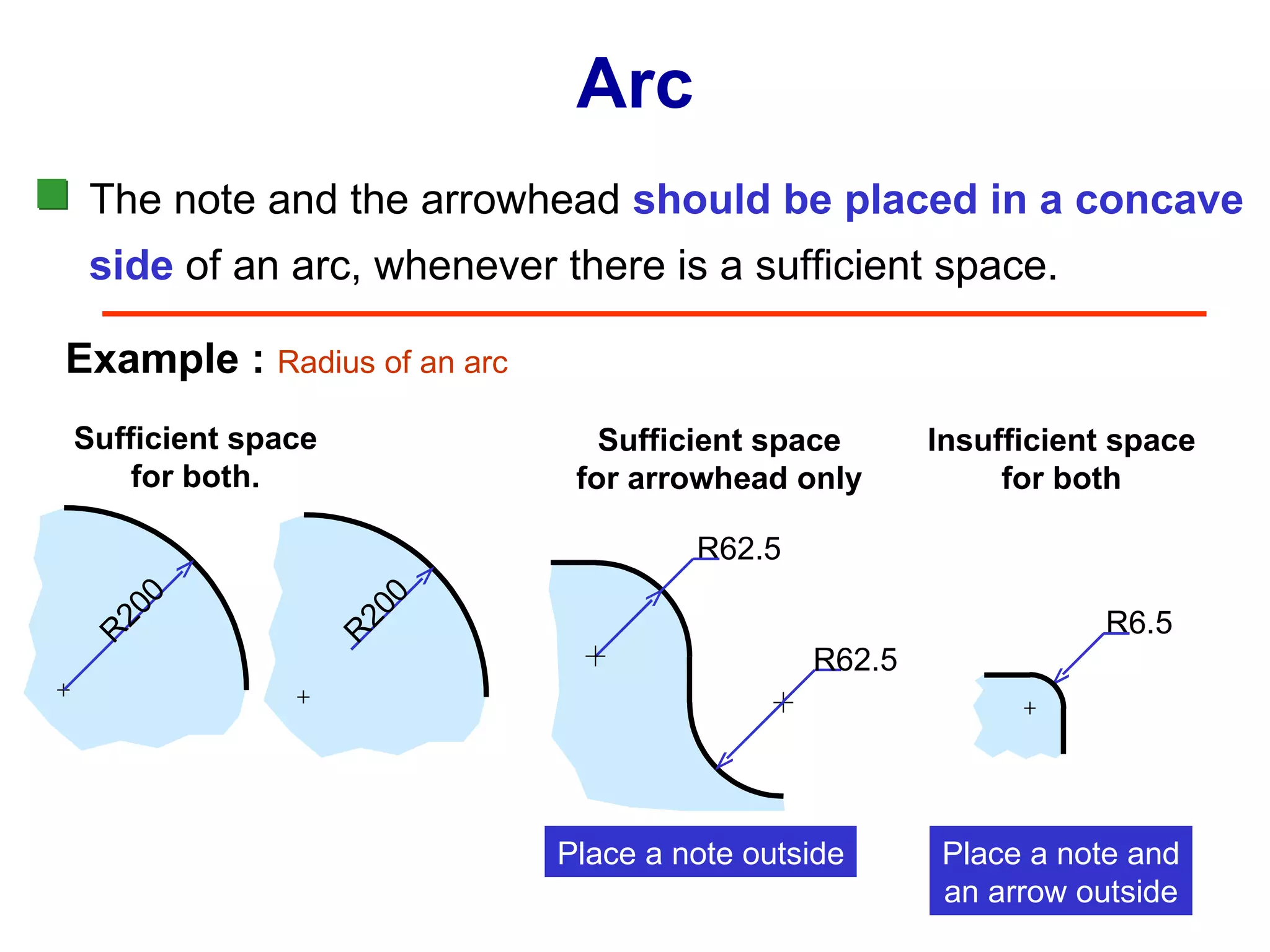
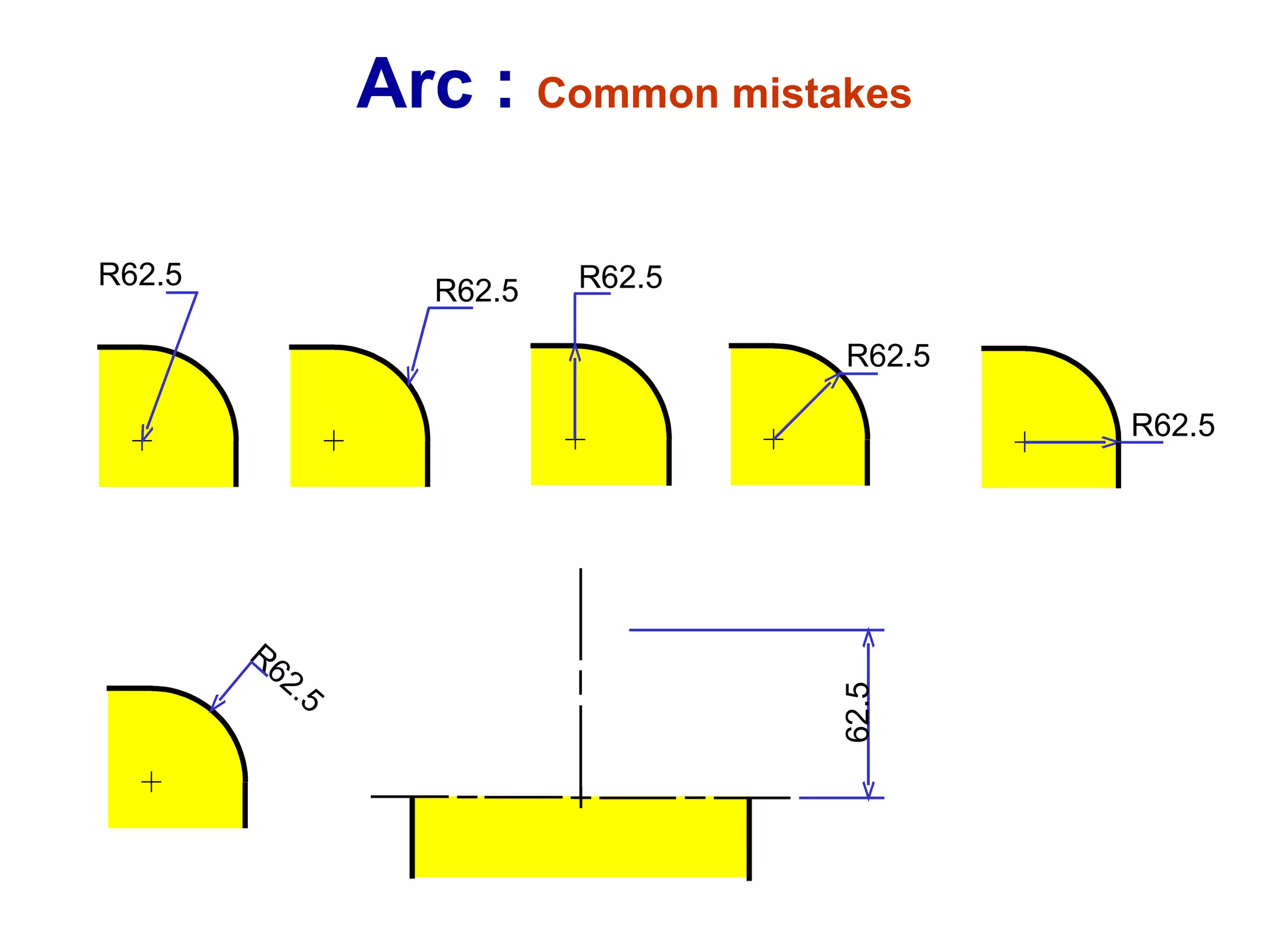
Techniques for dimensioning length, angle, and radius, including appropriate components and common mistakes.
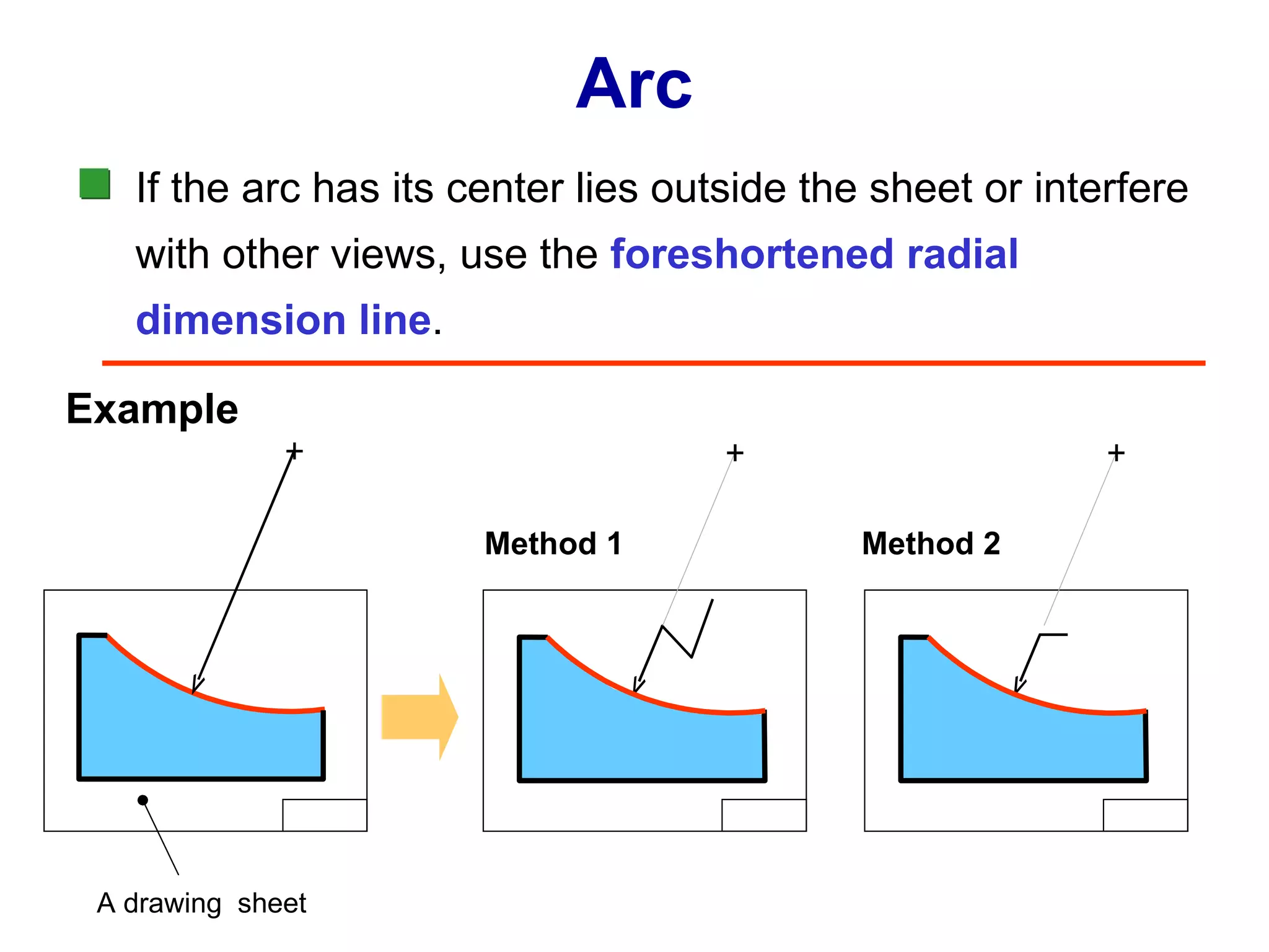
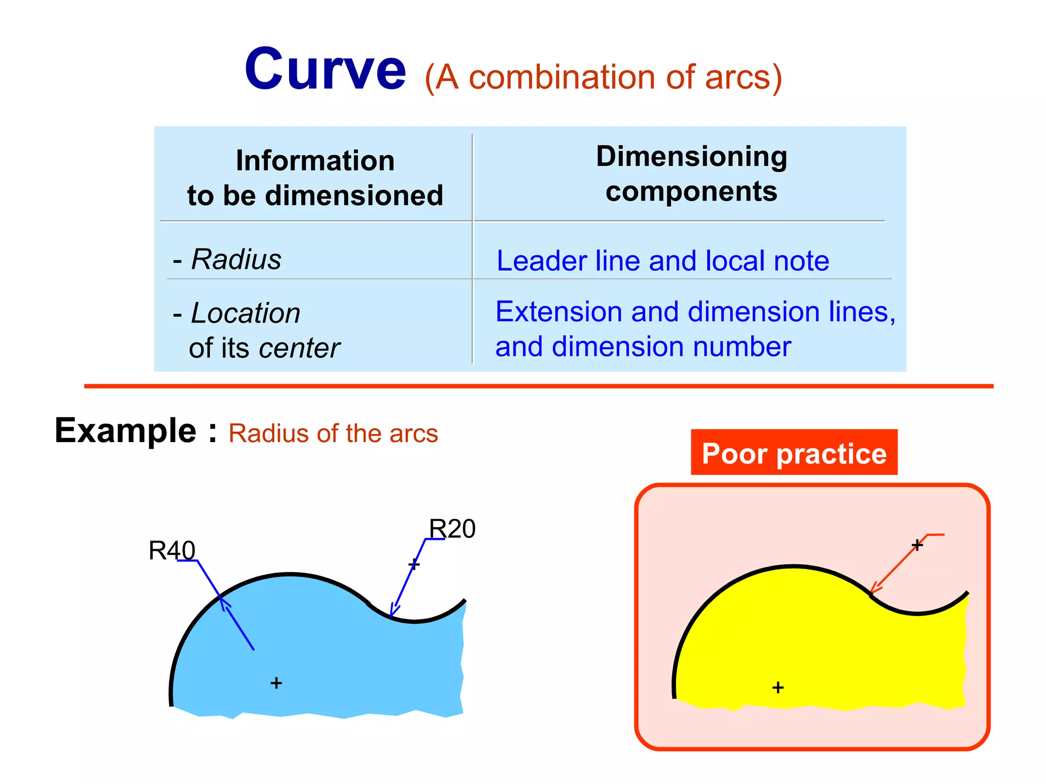
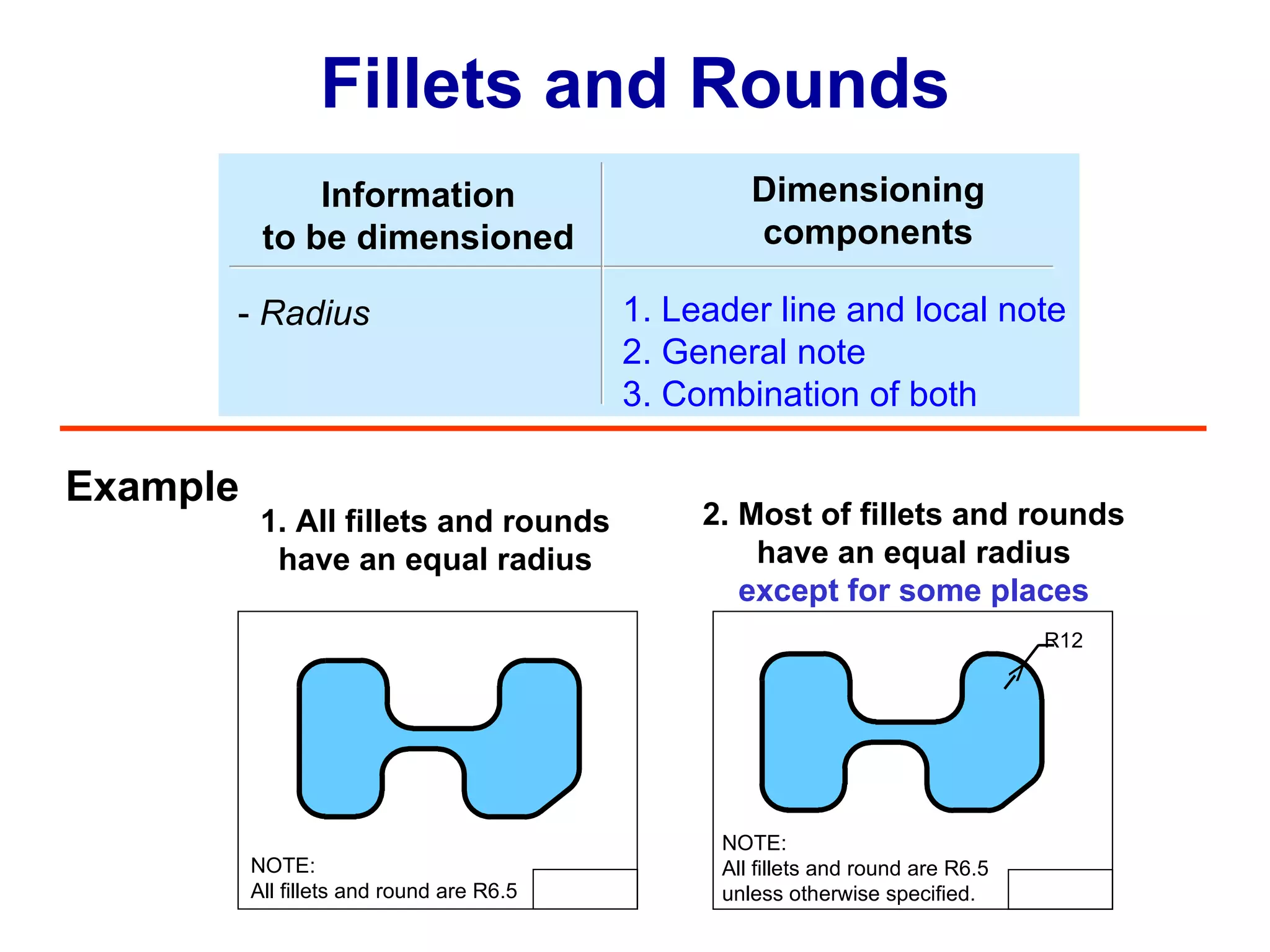
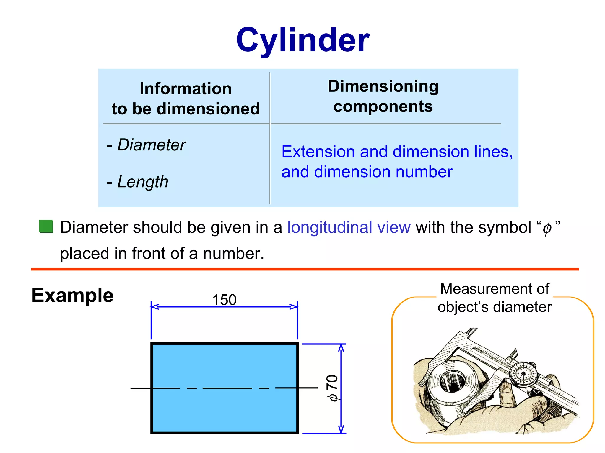
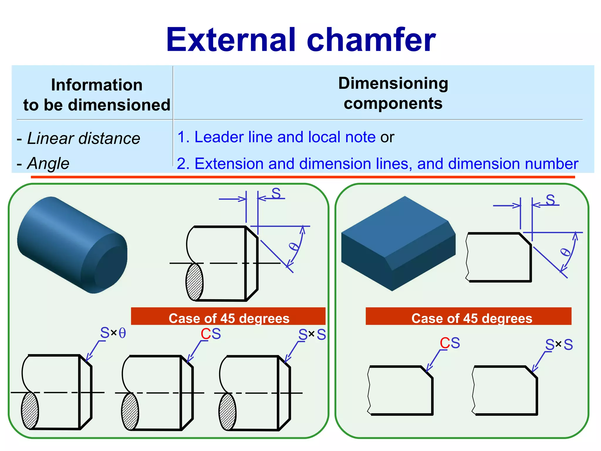
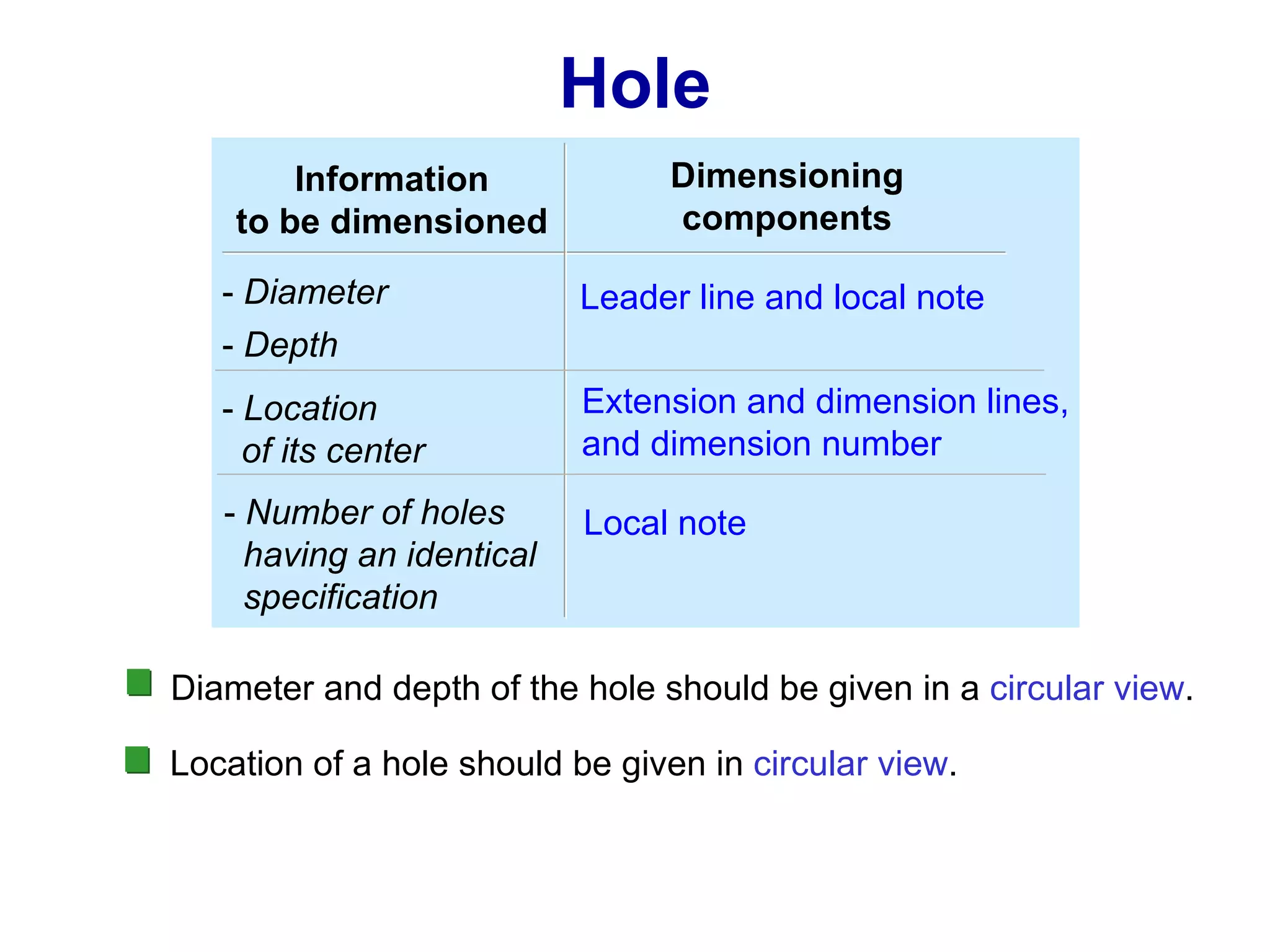
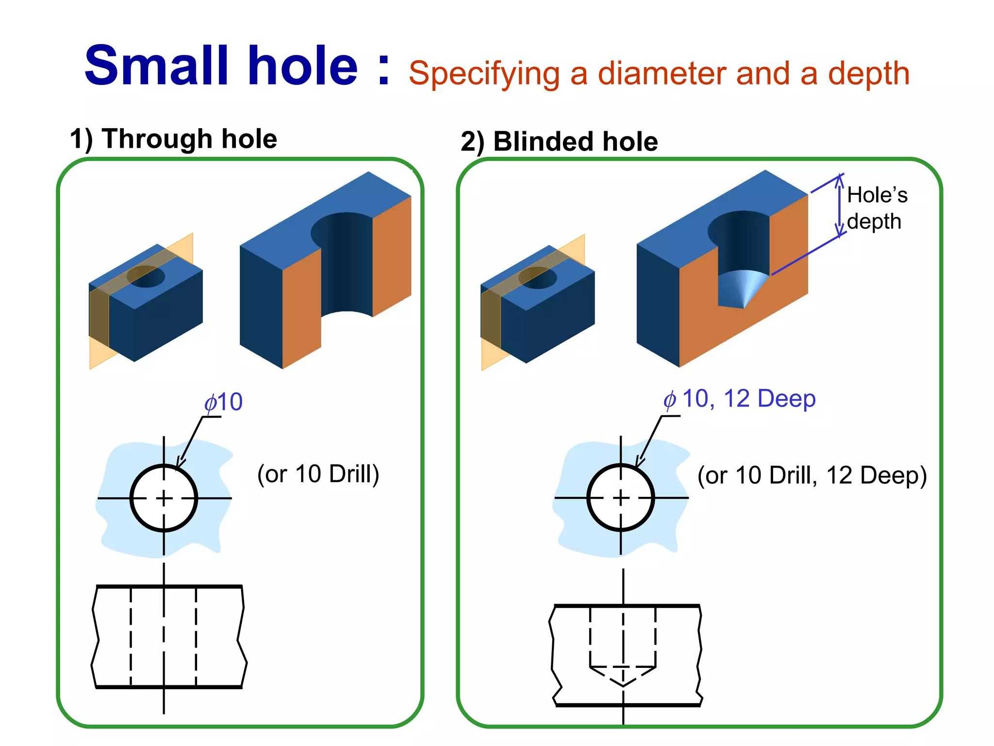
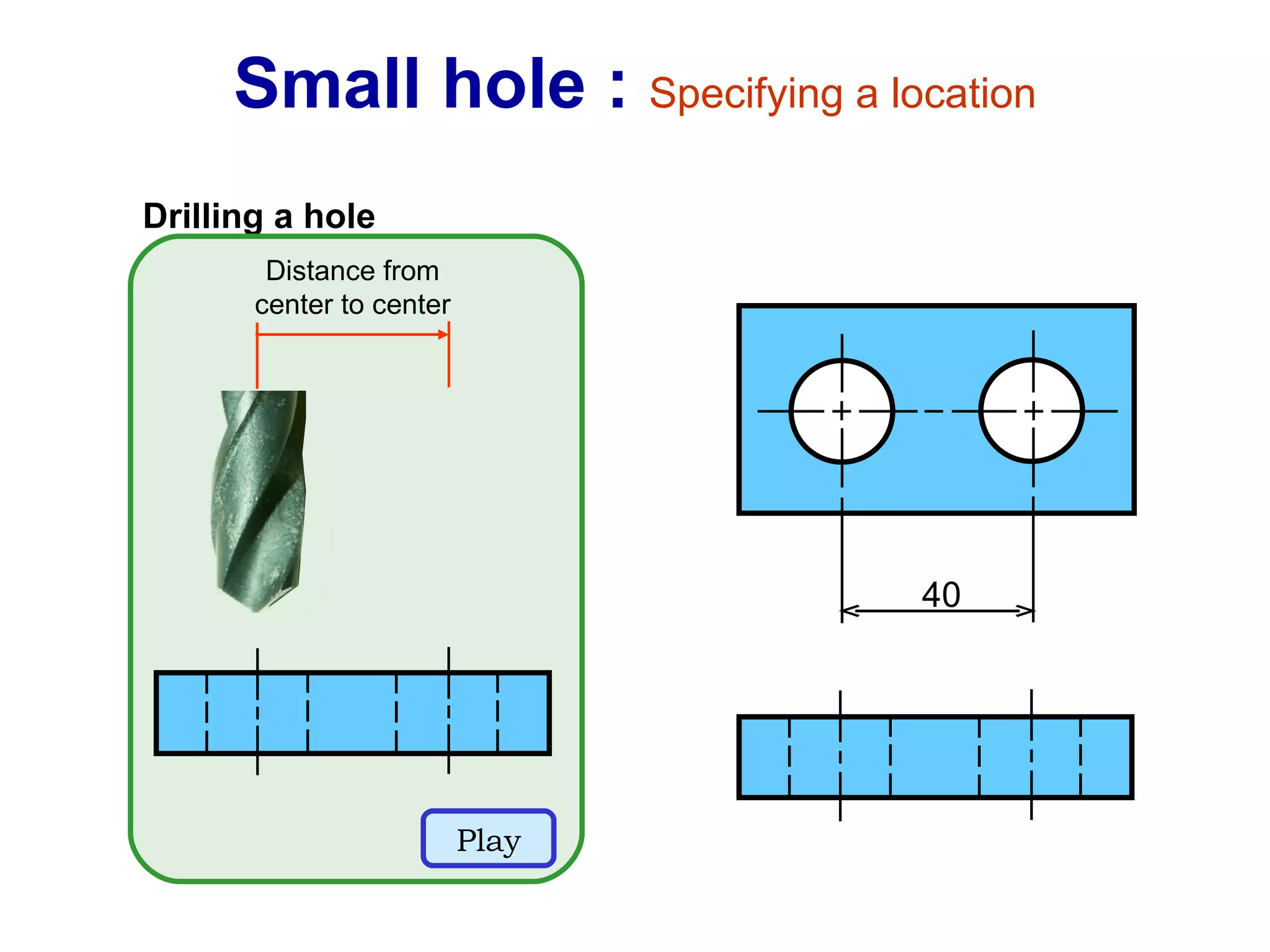
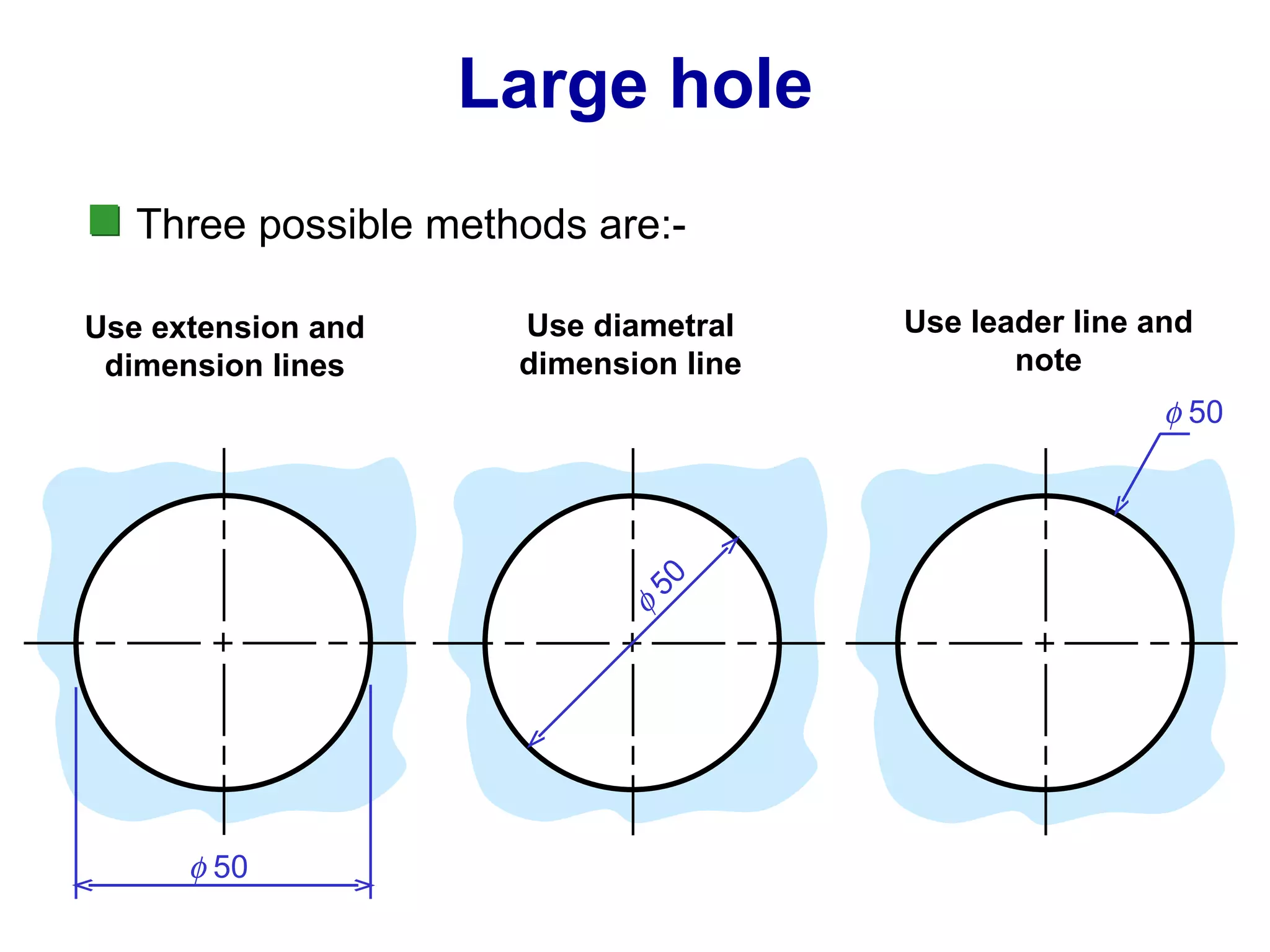
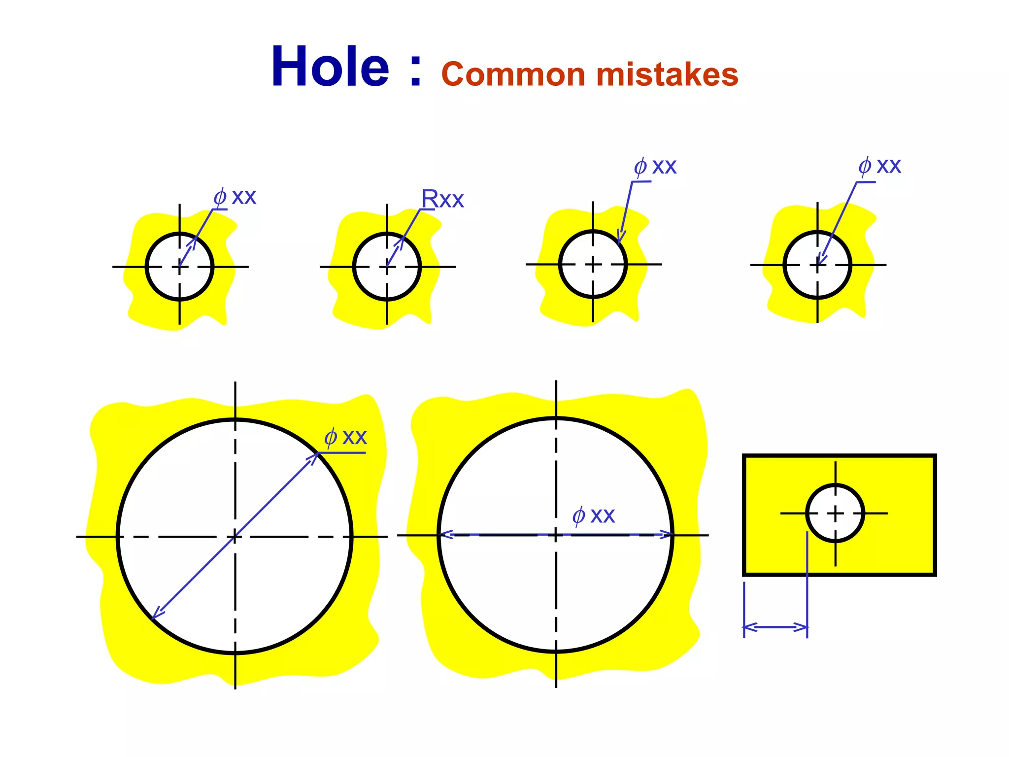
Methods for dimensioning curves, fillets, cylinder dimensions, hole specifications, and common mistakes encountered.
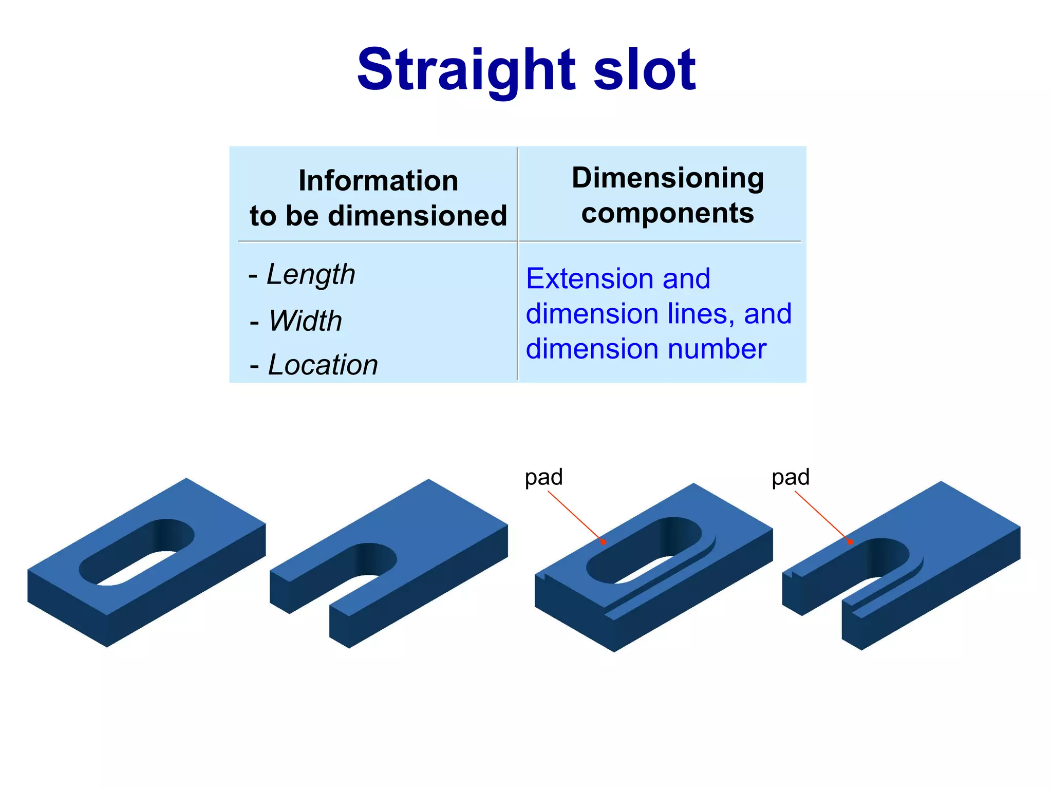
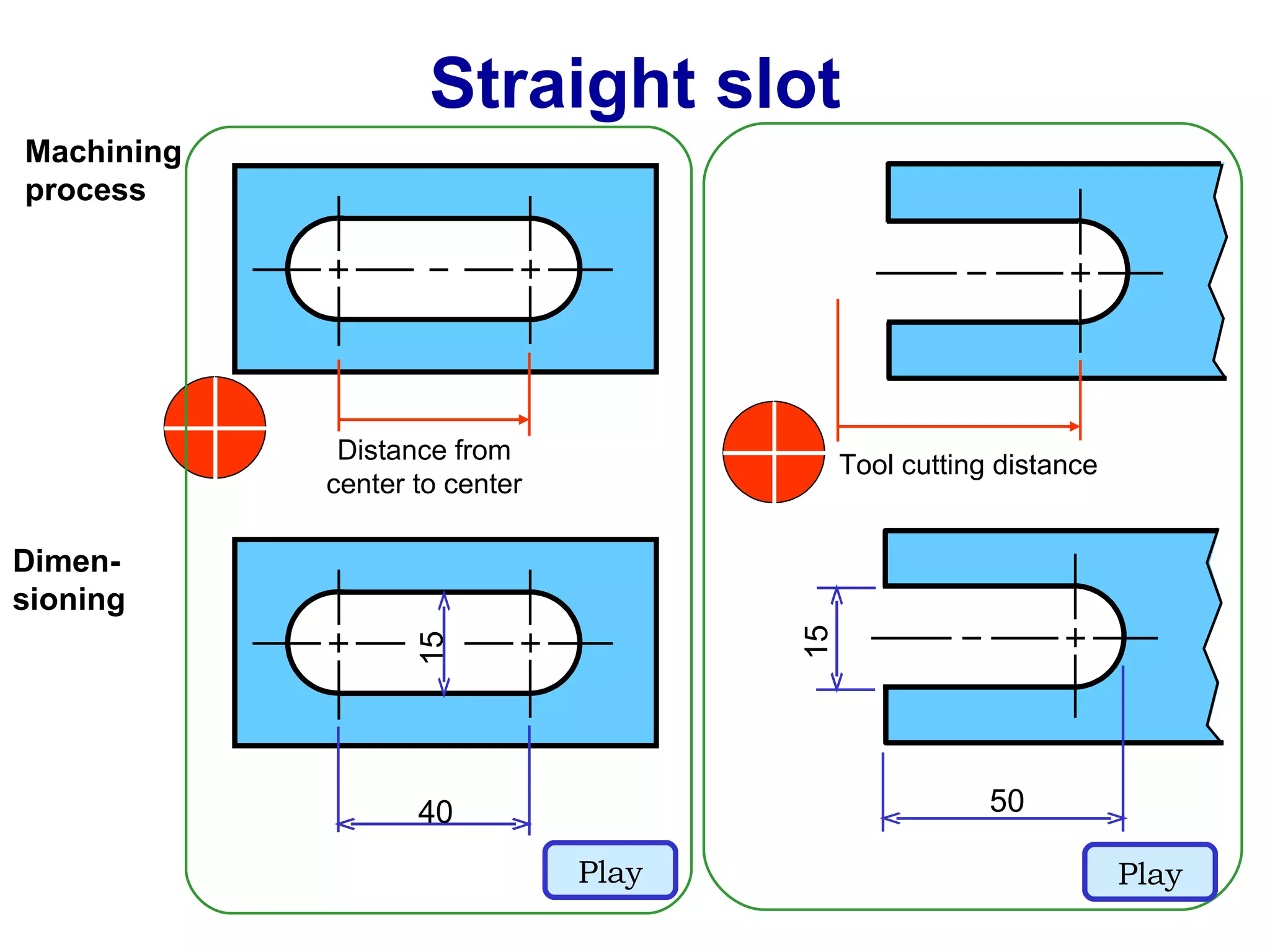
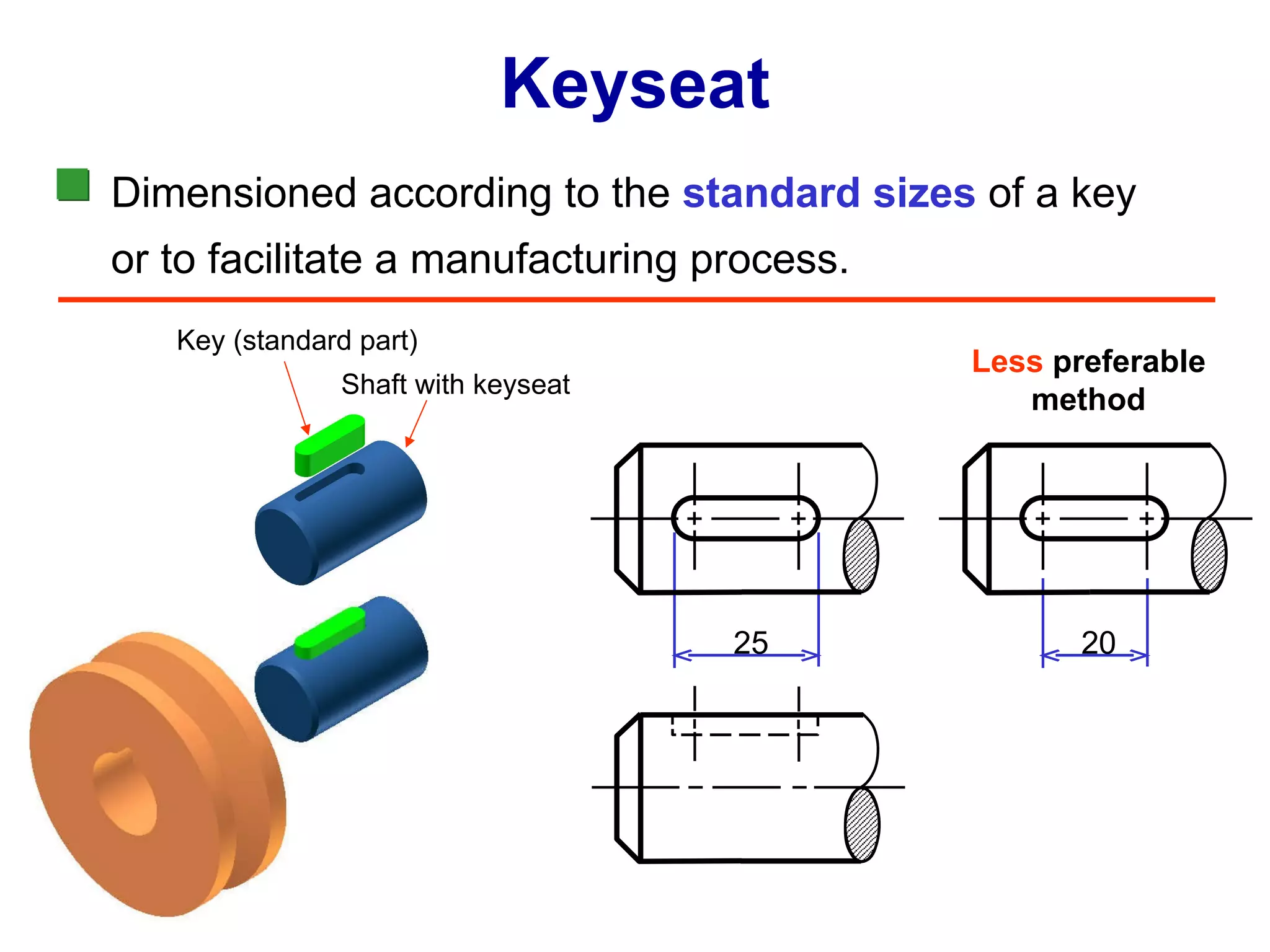
Dimensioning slots and keyseats with emphasis on dimensions for straight slots and standard part size considerations.
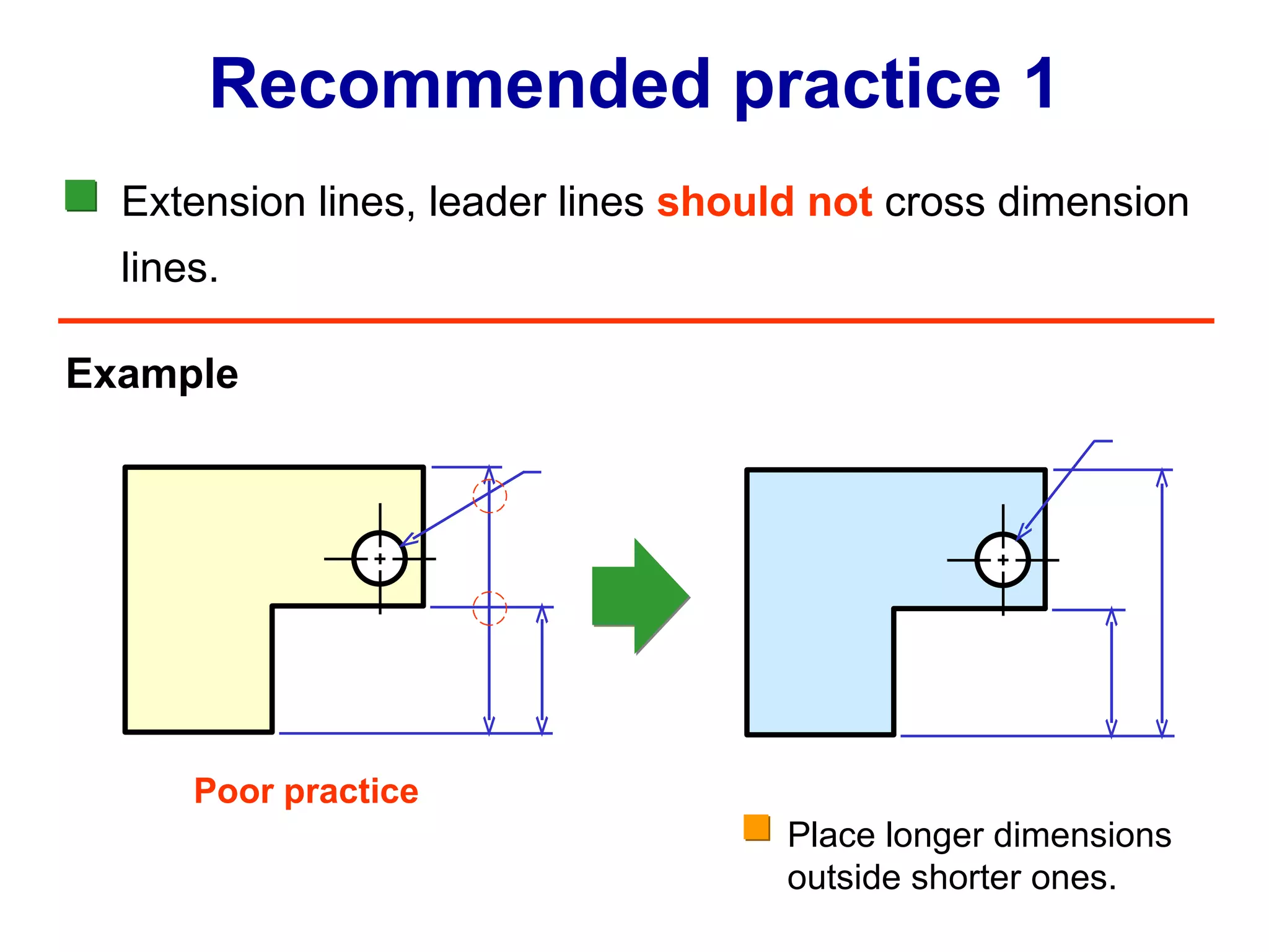
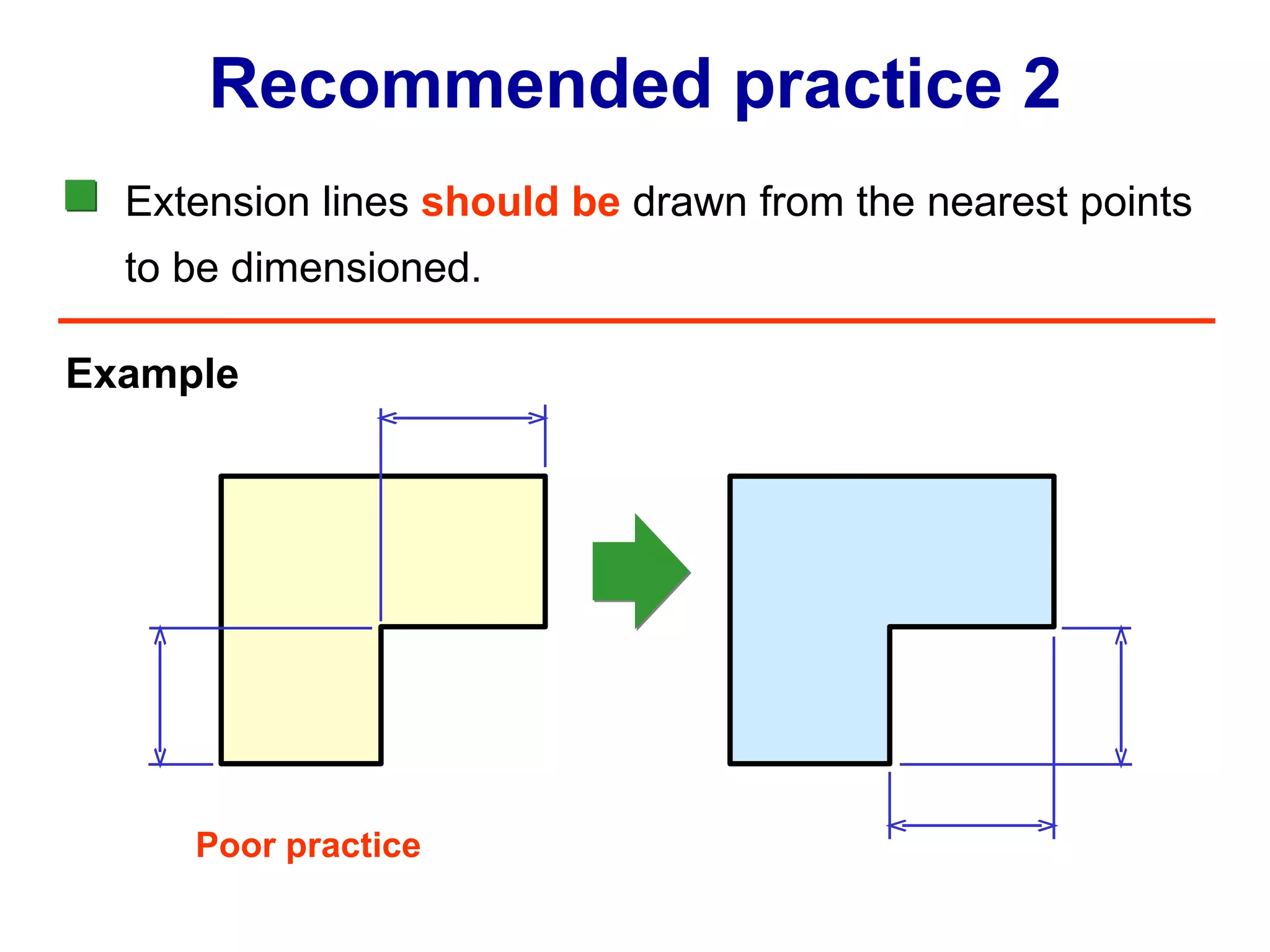
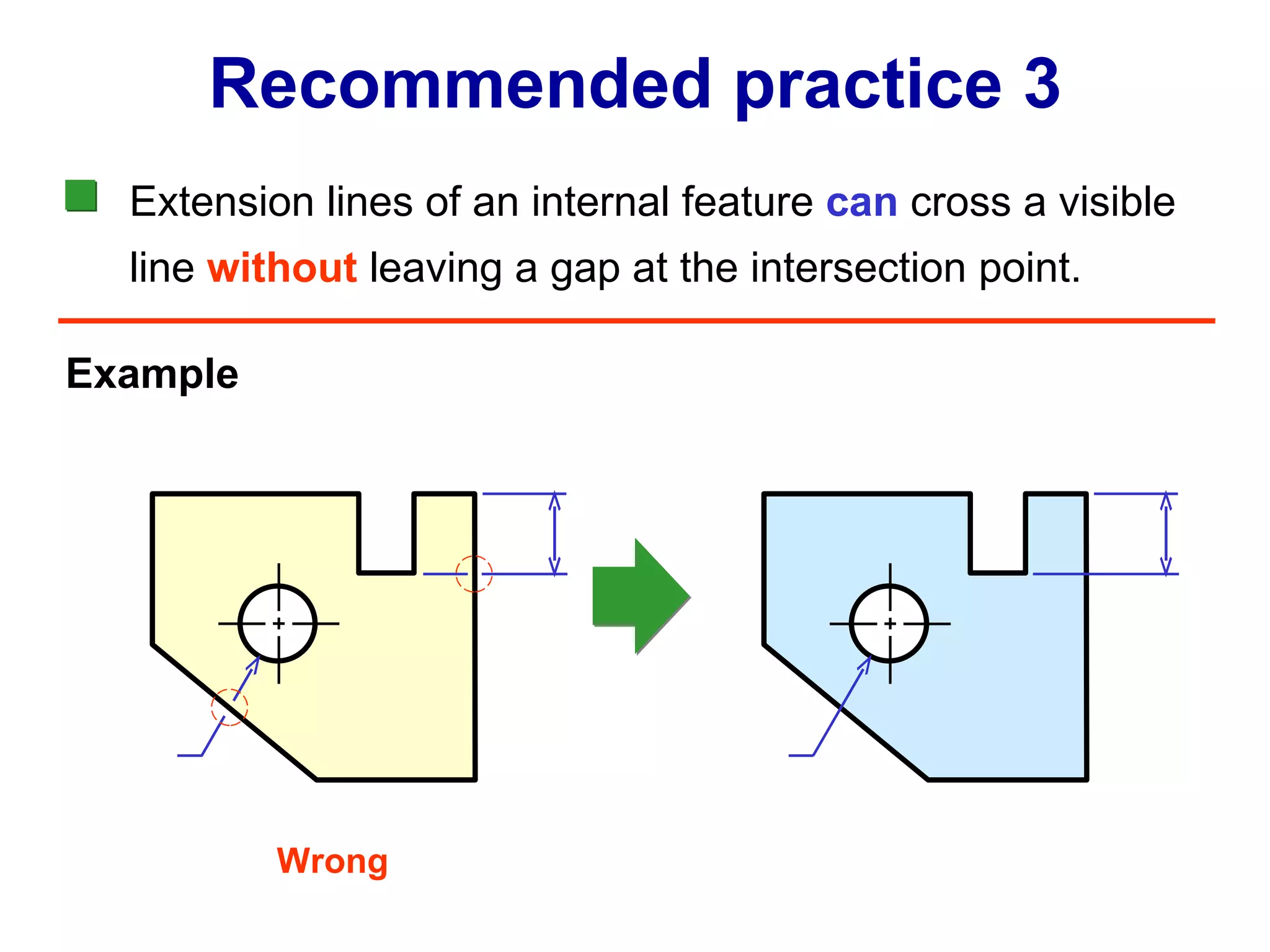
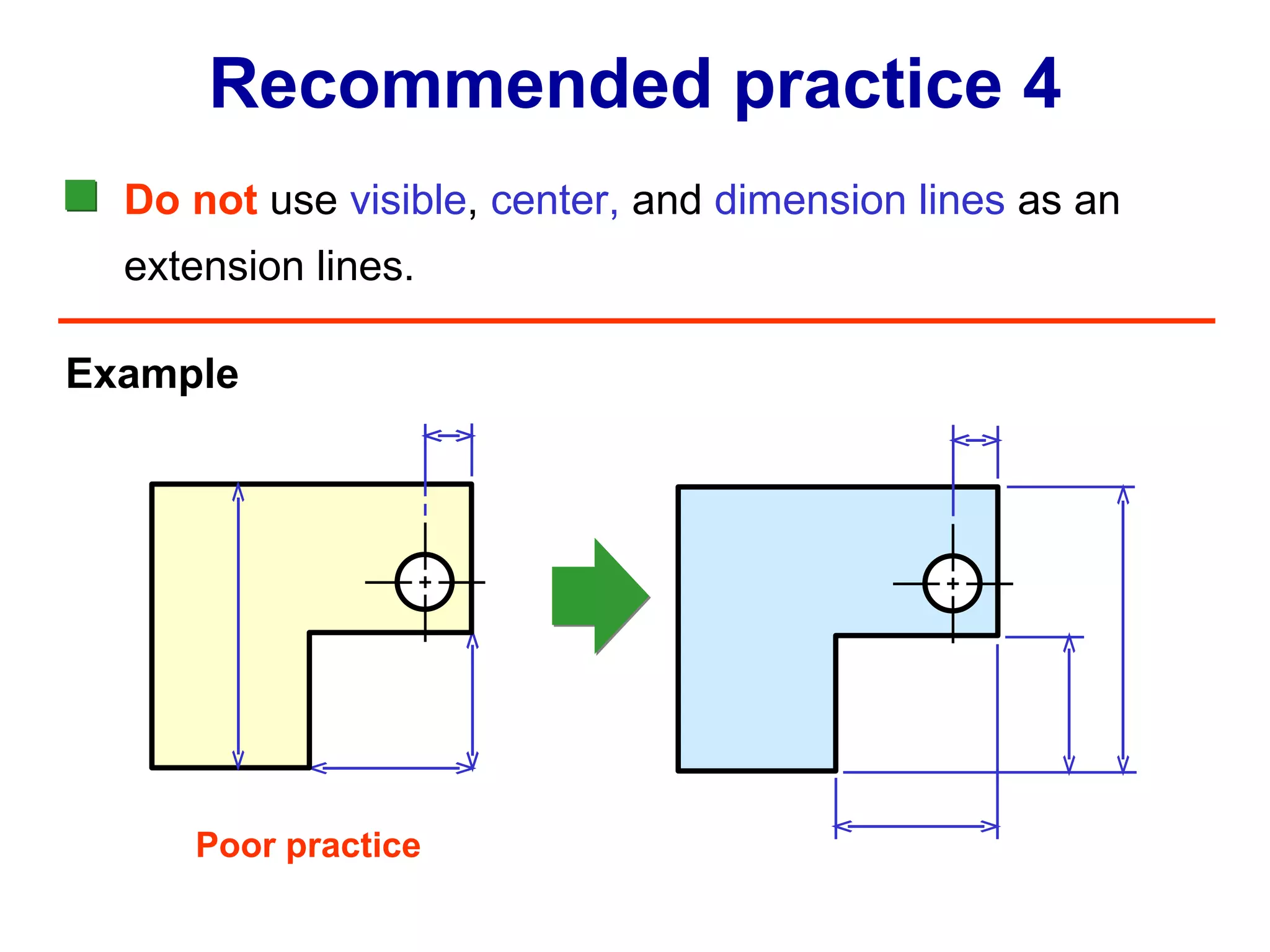
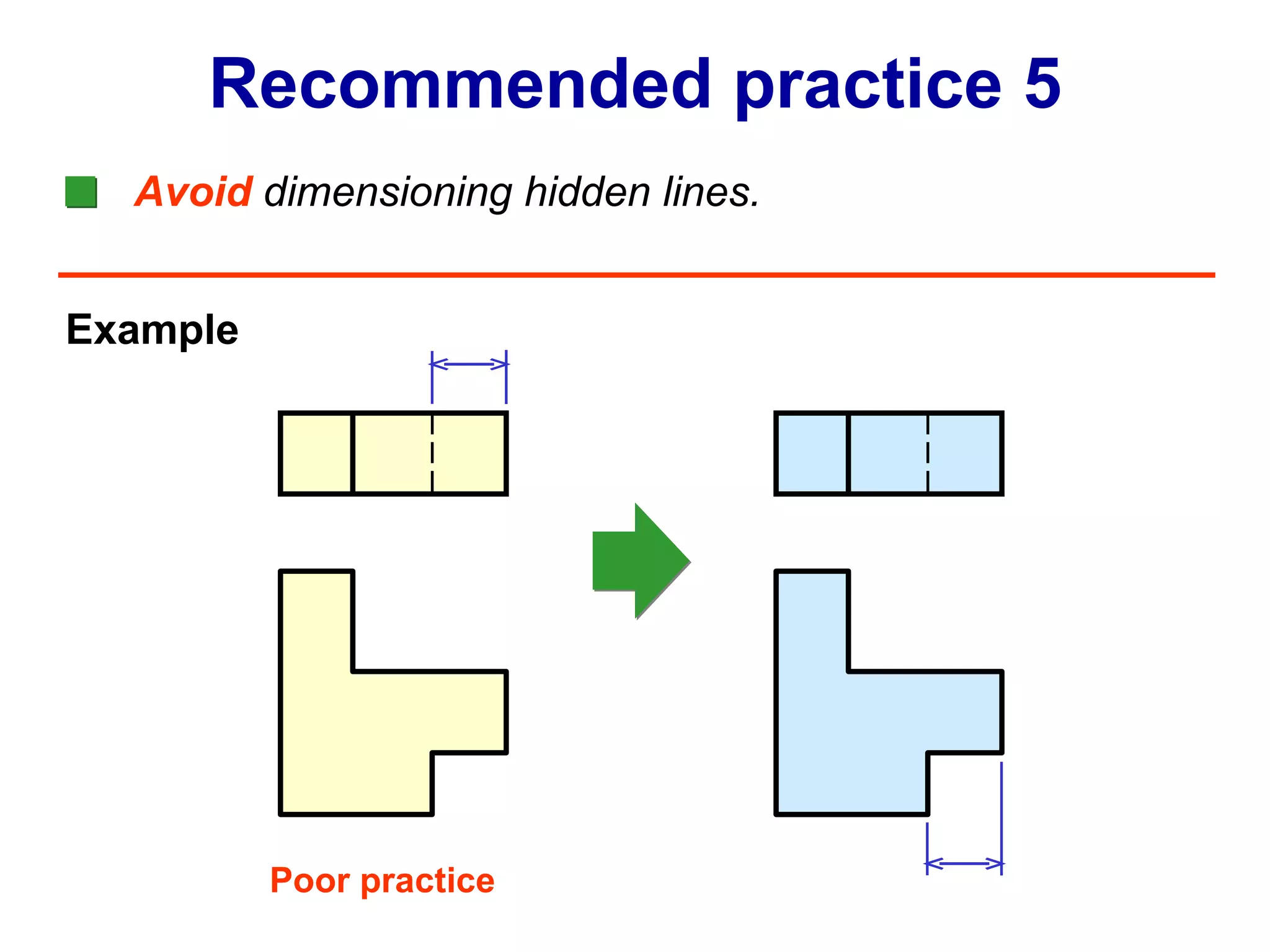
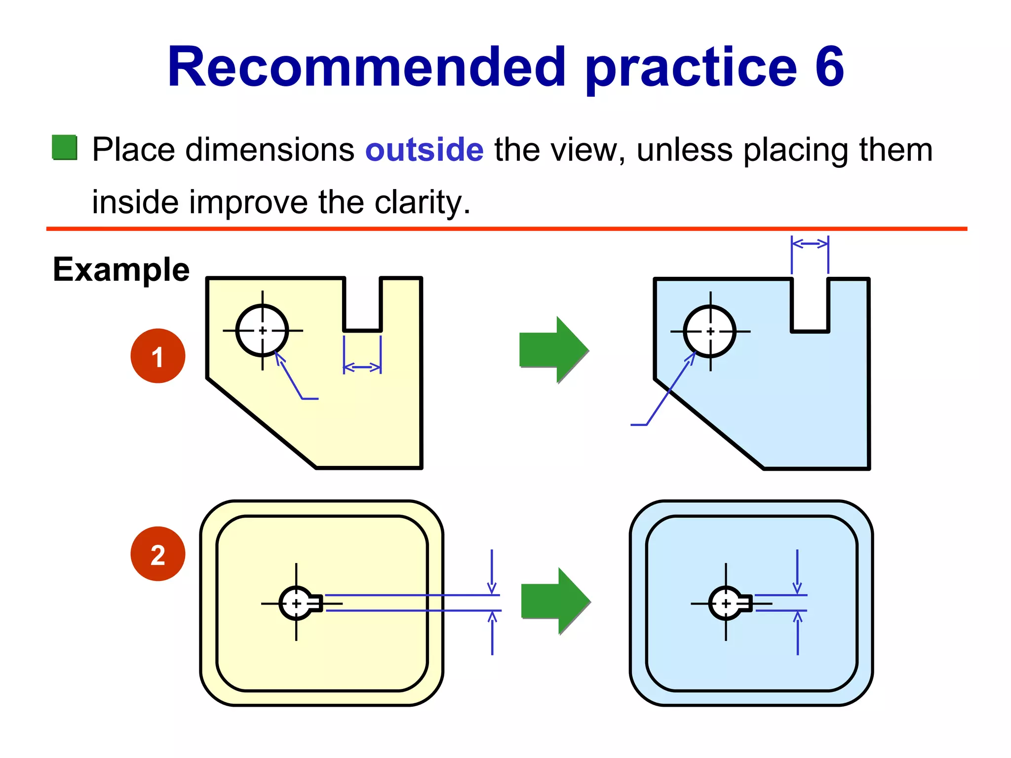
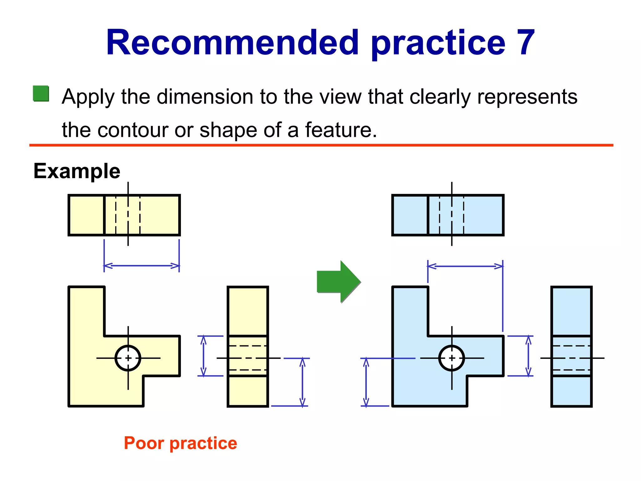
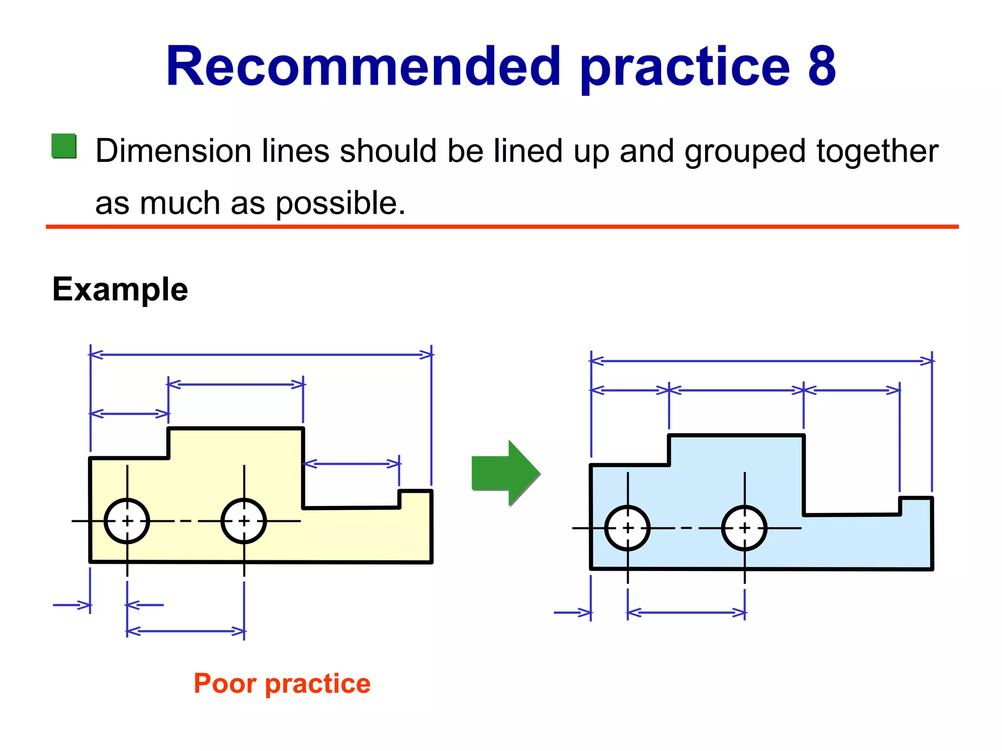
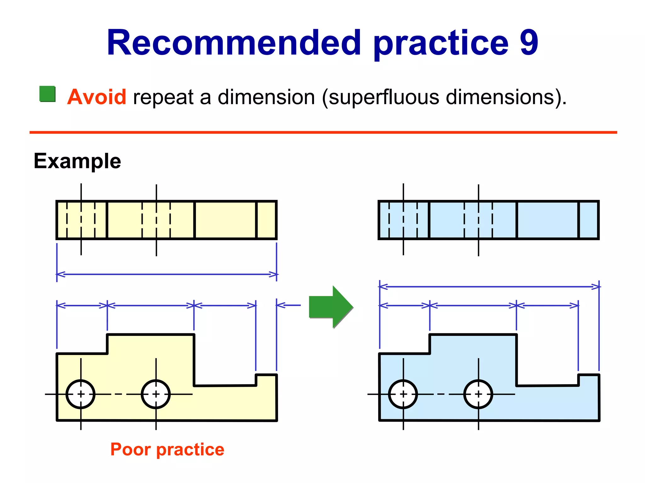
Guidelines and recommendations for placing dimensions, managing extension lines, avoiding redundancies.
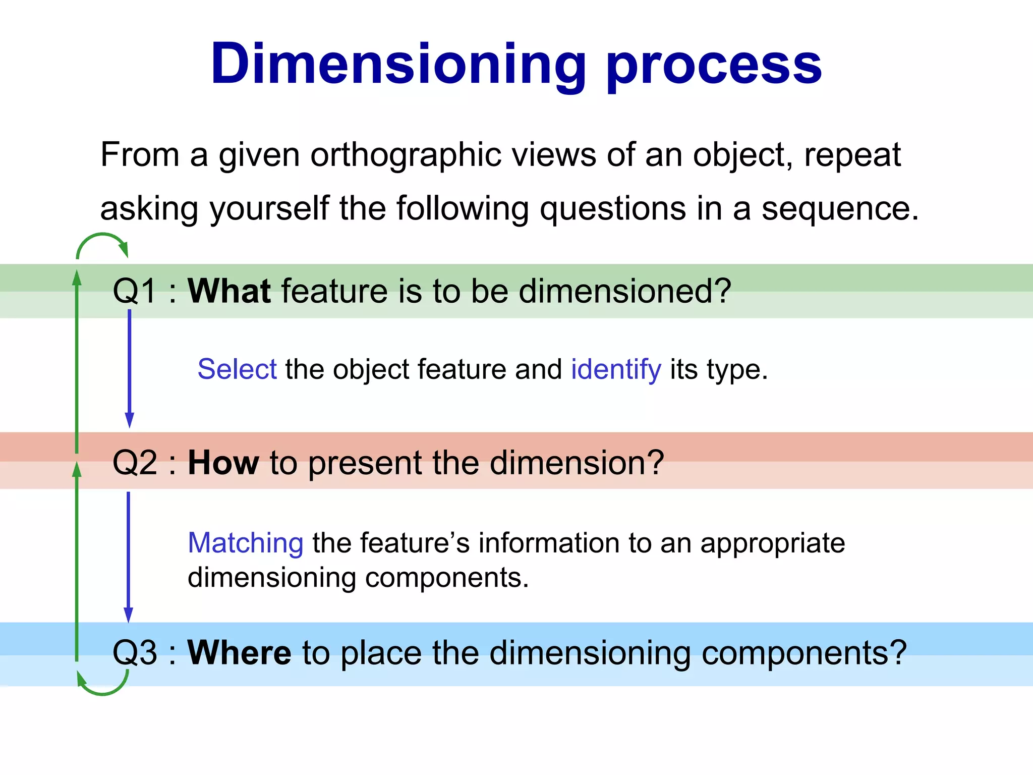
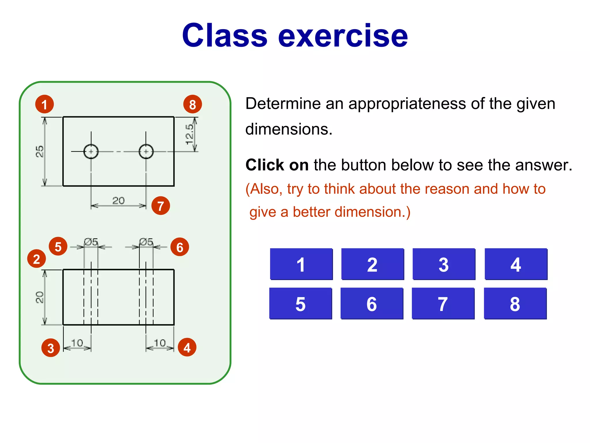
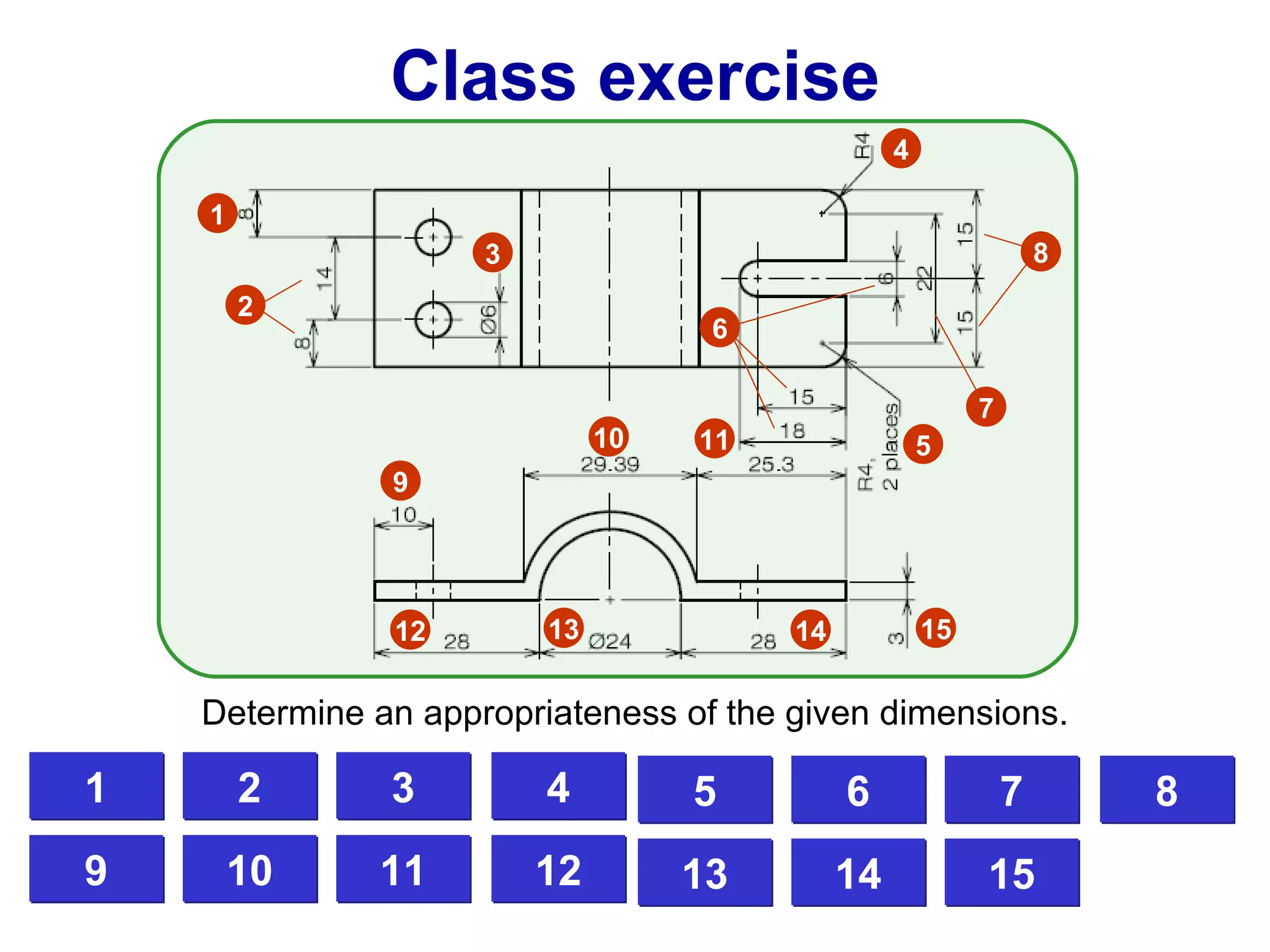
Problem solving steps for dimensioning, including questions to evaluate features and appropriateness through exercises.