Downloaded 298 times
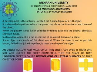
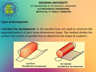
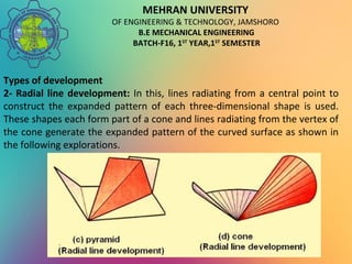
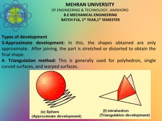
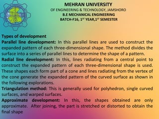
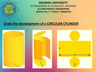
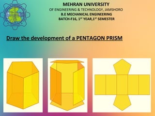
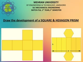
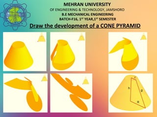
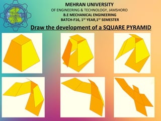
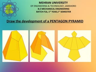
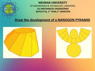
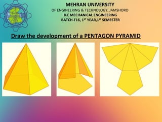
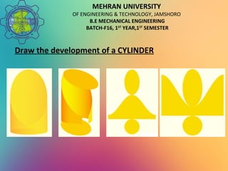
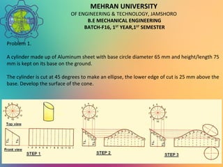
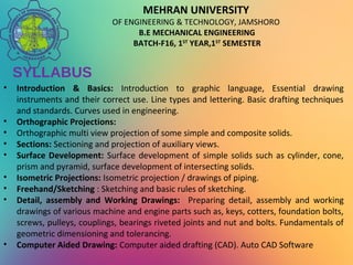

The document discusses surface development in engineering drawing, specifically for mechanical engineering students, focusing on the transition from 3D objects to 2D patterns. It outlines types of surface development methods, such as parallel line, radial line, approximate development, and triangulation, and emphasizes practical applications in the sheet metal industry. Furthermore, it includes examples and problems for students to practice developing surfaces of various solids, supported by a syllabus detailing essential drawing techniques and standards.