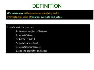
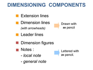
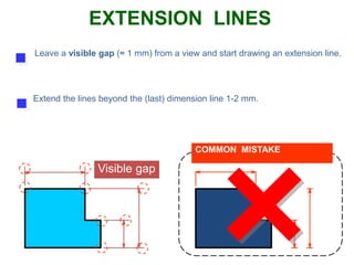
UNIT 2
Dimensioning
Subject : Basics of Engineering Graphics -
Diploma Sem 2
Contents
Introduction
Dimensioning components
Dimensioning object’ s features
Placement of dimensions.
DEFINITION
Dimensioning is the process of specifying part’ s
information by using of figures, symbols and notes.
This information are such as:
1. Sizes and locations of features
2. Material’s type
3. Number required
4. Kind of surface finish
5. Manufacturing process
6. Size and geometric tolerances
DIMENSIONING COMPONENTS
Extension lines
Dimension lines
(with arrowheads)
Leader lines
Dimension figures
Notes :
- local note
- general note
Drawn with
4H pencil
Lettered with
2H pencil.
indicate the location on the object’s features that
are dimensioned.
EXTENSION LINES
EXTENSION LINES
Leave a visible gap (≈ 1 mm) from a view and start drawing an extension line.
Extend the lines beyond the (last) dimension line 1-2 mm.
Visible gap
COMMON MISTAKE
Do not break the lines as they cross object lines.
COMMON MISTAKE
Continuous
EXTENSION LINES
Dimension lines should not be spaced too close
to each other and to the view.
11
34
Leave a space at least
2 times of a letter height.
16
35
DIMENSION LINES
Leave a space at least
1 time of a letter height.
DIMENSION FIGURES
The height of figures is suggested to be 2.5~3 mm.
Place the numbers at about 1 mm above dimension
line and between extension lines.
COMMON MISTAKE
11
11
34
34
16.25
16.25
or
DIMENSION FIGURES
When there is not enough space for figure or
arrows, put it outside either of the extension lines.
1
Not enough space
for figures
Not enough space
for arrows
1 1
The JIS and ISO standards adopt the unit of
Angular dimension in degree with a symbol “o”
place behind the figures (and if necessary
minutes and seconds may be used together).
DIMENSION FIGURES : UNITS
Length dimension in millimeters without
specifying a unit symbol “mm”.
1. Aligned method
2. Unidirectional method
The dimension figures are placed so that they are readable from the
bottom and right side of the drawing.
The dimension figures are placed so that they can be read from the
bottom of the drawing.
Do not use both system on the same drawing or on the same series of
drawing (JIS Z8317)
DIMENSIONING METHOD
30
30
30
30
EXAMPLE : Dimension of length using aligned method.
30
30
30
30
3030
30
30
EXAMPLE : Dimension of length using unidirectional method.
45o
45o
45o
45o
EXAMPLE : Dimension of angle using aligned method.
45o
45o
45o
45o
45o
45o
45o
45o
EXAMPLE : Dimension of angle using unidirectional method.
LOCAL NOTES
Place the notes near to the feature which they
apply, and should be placed outside the view.
Always read horizontally.
10 Drill
COMMON MISTAKES
10 Drill
≈ 10mm
10Drill
Too far
THE BASIC CONCEPT
Dimensioning is accomplished by adding size and location information
necessary to manufacture the object and component.
Clear
Complete
Facilitate the
- manufacturing method
- measurement method
This information have to be
L
L
S
S
S
Designed
part
EXAMPLE
To manufacture this part
we need to know…
1. Width, depth and
thickness of the part.
2. Diameter and depth
of the hole.
3. Location of the holes.
“S” denotes size dimension.
“L” denotes location dimension.
S
L
L
ANGLE
To dimension an angle use circular dimension
line having the center at the vertex of the angle.
COMMON MISTAKE
FILLETS AND ROUNDS
Give the radius of a typical fillet only by using a
local note.
R6.5
If all fillets and rounds are uniform in size,
dimension may be omitted, but it is necessary to
add the note “ All fillets and round are Rxx. ”
NOTE:
All fillets and round are R6.5
Drawing sheet
R12
unless otherwise specified.
NOTE:
All fillets and round are R6.5
f xx
Use leader line and local note to specify diameter
and hole’s depth in the circular view.
HOLES : SMALL SIZE
xx Drill, Thru.
1) Through thickness hole
f xx Thru.
or
xx Drill.
or or
f xx, yy Deep
HOLES : SMALL SIZE
or
xx Drill, yy Deep
Hole’s
depth
Use leader line and local note to specify diameter
and hole’s depth in the circular view.
2) Blind hole
f xx
Use extension and
dimension lines
Use diametral
dimension line
Use leader line
and note
HOLES : LARGE SIZE
COMMON MISTAKE
f xx
f xx f xx
Rxx
f xx
HOLES
f xx
CHAMFER
Use leader line and note to indicate linear
distance and angle of the chamfer.
S
S q
For a 45o chamfer
S SCS
or
ROUNDED-END SHAPES
R12
f 12
21
5
Dimensioned according to the manufacturing
method used.
Center to Center Distance
ROUNDED-END SHAPES
R12
21
5
12
Dimensioned according to the manufacturing
method used.
Center to Center Distance
ROUNDED-END SHAPES
Dimensioned according to the manufacturing
method used.
R12
21
12
16
ROUNDED-END SHAPES
R12
27
12
Dimensioned according to the manufacturing
method used.
Tool cutting distance
ROUNDED-END SHAPES
Dimensioned according to the standard sizes of
another part to be assembled or manufacturing
method used.
25
Key
(standard part)
ROUNDED-END SHAPES
Dimensioned according to the standard sizes of
another part to be assembled or manufacturing
method used.
20
1. Extension lines, leader lines should not cross
dimension lines.
POOR GOOD
RECOMMENDED PRACTICE
2. Extension lines should be drawn from the nearest
points to be dimensioned.
POOR GOOD
RECOMMENDED PRACTICE
3. Extension lines of internal feature can cross visible
lines without leaving a gap at the intersection point.
WRONG CORRECT
RECOMMENDED PRACTICE
4. Do not use object line, center line, and dimension
line as an extension lines.
POOR GOOD
RECOMMENDED PRACTICE
POOR GOOD
5. Avoid dimensioning hidden lines.
RECOMMENDED PRACTICE
POOR GOOD
6. Place dimensions outside the view, unless
placing them inside improve the clarity.
RECOMMENDED PRACTICE
JUST OK !!! BETTER
RECOMMENDED PRACTICE
6. Place dimensions outside the view, unless
placing them inside improve the clarity.
7. Apply the dimension to the view that clearly show
the shape or features of an object.
POOR GOOD
RECOMMENDED PRACTICE
8. Dimension lines should be lined up and grouped
together as much as possible.
POOR GOOD
RECOMMENDED PRACTICE
9. Do not repeat a dimension.
POOR GOOD
RECOMMENDED PRACTICE
References
• http://www.engineering108.com/pages/Engineering
_graphics/Engineering_graphics_tutorials_free_dow
nload.html
• A text book of engineering graphics- Prof. P.J SHAH
• Engineering Drawing-N.D.Bhatt
• Engineering Drawing-P.S.Gill

Dimensioning unit 2

  • 1.
    UNIT 2 Dimensioning Subject :Basics of Engineering Graphics - Diploma Sem 2
  • 2.
  • 3.
    DEFINITION Dimensioning is theprocess of specifying part’ s information by using of figures, symbols and notes. This information are such as: 1. Sizes and locations of features 2. Material’s type 3. Number required 4. Kind of surface finish 5. Manufacturing process 6. Size and geometric tolerances
  • 4.
    DIMENSIONING COMPONENTS Extension lines Dimensionlines (with arrowheads) Leader lines Dimension figures Notes : - local note - general note Drawn with 4H pencil Lettered with 2H pencil.
  • 5.
    indicate the locationon the object’s features that are dimensioned. EXTENSION LINES
  • 6.
    EXTENSION LINES Leave avisible gap (≈ 1 mm) from a view and start drawing an extension line. Extend the lines beyond the (last) dimension line 1-2 mm. Visible gap COMMON MISTAKE
  • 7.
    Do not breakthe lines as they cross object lines. COMMON MISTAKE Continuous EXTENSION LINES
  • 8.
    Dimension lines shouldnot be spaced too close to each other and to the view. 11 34 Leave a space at least 2 times of a letter height. 16 35 DIMENSION LINES Leave a space at least 1 time of a letter height.
  • 9.
    DIMENSION FIGURES The heightof figures is suggested to be 2.5~3 mm. Place the numbers at about 1 mm above dimension line and between extension lines. COMMON MISTAKE 11 11 34 34
  • 10.
    16.25 16.25 or DIMENSION FIGURES When thereis not enough space for figure or arrows, put it outside either of the extension lines. 1 Not enough space for figures Not enough space for arrows 1 1
  • 11.
    The JIS andISO standards adopt the unit of Angular dimension in degree with a symbol “o” place behind the figures (and if necessary minutes and seconds may be used together). DIMENSION FIGURES : UNITS Length dimension in millimeters without specifying a unit symbol “mm”.
  • 12.
    1. Aligned method 2.Unidirectional method The dimension figures are placed so that they are readable from the bottom and right side of the drawing. The dimension figures are placed so that they can be read from the bottom of the drawing. Do not use both system on the same drawing or on the same series of drawing (JIS Z8317) DIMENSIONING METHOD
  • 13.
    30 30 30 30 EXAMPLE : Dimensionof length using aligned method.
  • 14.
    30 30 30 30 3030 30 30 EXAMPLE : Dimensionof length using unidirectional method.
  • 15.
    45o 45o 45o 45o EXAMPLE : Dimensionof angle using aligned method.
  • 16.
    45o 45o 45o 45o 45o 45o 45o 45o EXAMPLE : Dimensionof angle using unidirectional method.
  • 17.
    LOCAL NOTES Place thenotes near to the feature which they apply, and should be placed outside the view. Always read horizontally. 10 Drill COMMON MISTAKES 10 Drill ≈ 10mm 10Drill Too far
  • 18.
    THE BASIC CONCEPT Dimensioningis accomplished by adding size and location information necessary to manufacture the object and component. Clear Complete Facilitate the - manufacturing method - measurement method This information have to be
  • 19.
    L L S S S Designed part EXAMPLE To manufacture thispart we need to know… 1. Width, depth and thickness of the part. 2. Diameter and depth of the hole. 3. Location of the holes. “S” denotes size dimension. “L” denotes location dimension. S L L
  • 20.
    ANGLE To dimension anangle use circular dimension line having the center at the vertex of the angle. COMMON MISTAKE
  • 21.
    FILLETS AND ROUNDS Givethe radius of a typical fillet only by using a local note. R6.5 If all fillets and rounds are uniform in size, dimension may be omitted, but it is necessary to add the note “ All fillets and round are Rxx. ” NOTE: All fillets and round are R6.5 Drawing sheet R12 unless otherwise specified. NOTE: All fillets and round are R6.5
  • 22.
    f xx Use leaderline and local note to specify diameter and hole’s depth in the circular view. HOLES : SMALL SIZE xx Drill, Thru. 1) Through thickness hole f xx Thru. or xx Drill. or or
  • 23.
    f xx, yyDeep HOLES : SMALL SIZE or xx Drill, yy Deep Hole’s depth Use leader line and local note to specify diameter and hole’s depth in the circular view. 2) Blind hole
  • 24.
    f xx Use extensionand dimension lines Use diametral dimension line Use leader line and note HOLES : LARGE SIZE
  • 25.
    COMMON MISTAKE f xx fxx f xx Rxx f xx HOLES f xx
  • 26.
    CHAMFER Use leader lineand note to indicate linear distance and angle of the chamfer. S S q For a 45o chamfer S SCS or
  • 27.
    ROUNDED-END SHAPES R12 f 12 21 5 Dimensionedaccording to the manufacturing method used. Center to Center Distance
  • 28.
    ROUNDED-END SHAPES R12 21 5 12 Dimensioned accordingto the manufacturing method used. Center to Center Distance
  • 29.
    ROUNDED-END SHAPES Dimensioned accordingto the manufacturing method used. R12 21 12 16
  • 30.
    ROUNDED-END SHAPES R12 27 12 Dimensioned accordingto the manufacturing method used. Tool cutting distance
  • 31.
    ROUNDED-END SHAPES Dimensioned accordingto the standard sizes of another part to be assembled or manufacturing method used. 25 Key (standard part)
  • 32.
    ROUNDED-END SHAPES Dimensioned accordingto the standard sizes of another part to be assembled or manufacturing method used. 20
  • 33.
    1. Extension lines,leader lines should not cross dimension lines. POOR GOOD RECOMMENDED PRACTICE
  • 34.
    2. Extension linesshould be drawn from the nearest points to be dimensioned. POOR GOOD RECOMMENDED PRACTICE
  • 35.
    3. Extension linesof internal feature can cross visible lines without leaving a gap at the intersection point. WRONG CORRECT RECOMMENDED PRACTICE
  • 36.
    4. Do notuse object line, center line, and dimension line as an extension lines. POOR GOOD RECOMMENDED PRACTICE
  • 37.
    POOR GOOD 5. Avoiddimensioning hidden lines. RECOMMENDED PRACTICE
  • 38.
    POOR GOOD 6. Placedimensions outside the view, unless placing them inside improve the clarity. RECOMMENDED PRACTICE
  • 39.
    JUST OK !!!BETTER RECOMMENDED PRACTICE 6. Place dimensions outside the view, unless placing them inside improve the clarity.
  • 40.
    7. Apply thedimension to the view that clearly show the shape or features of an object. POOR GOOD RECOMMENDED PRACTICE
  • 41.
    8. Dimension linesshould be lined up and grouped together as much as possible. POOR GOOD RECOMMENDED PRACTICE
  • 42.
    9. Do notrepeat a dimension. POOR GOOD RECOMMENDED PRACTICE
  • 43.
    References • http://www.engineering108.com/pages/Engineering _graphics/Engineering_graphics_tutorials_free_dow nload.html • Atext book of engineering graphics- Prof. P.J SHAH • Engineering Drawing-N.D.Bhatt • Engineering Drawing-P.S.Gill