Download as PDF, PPTX
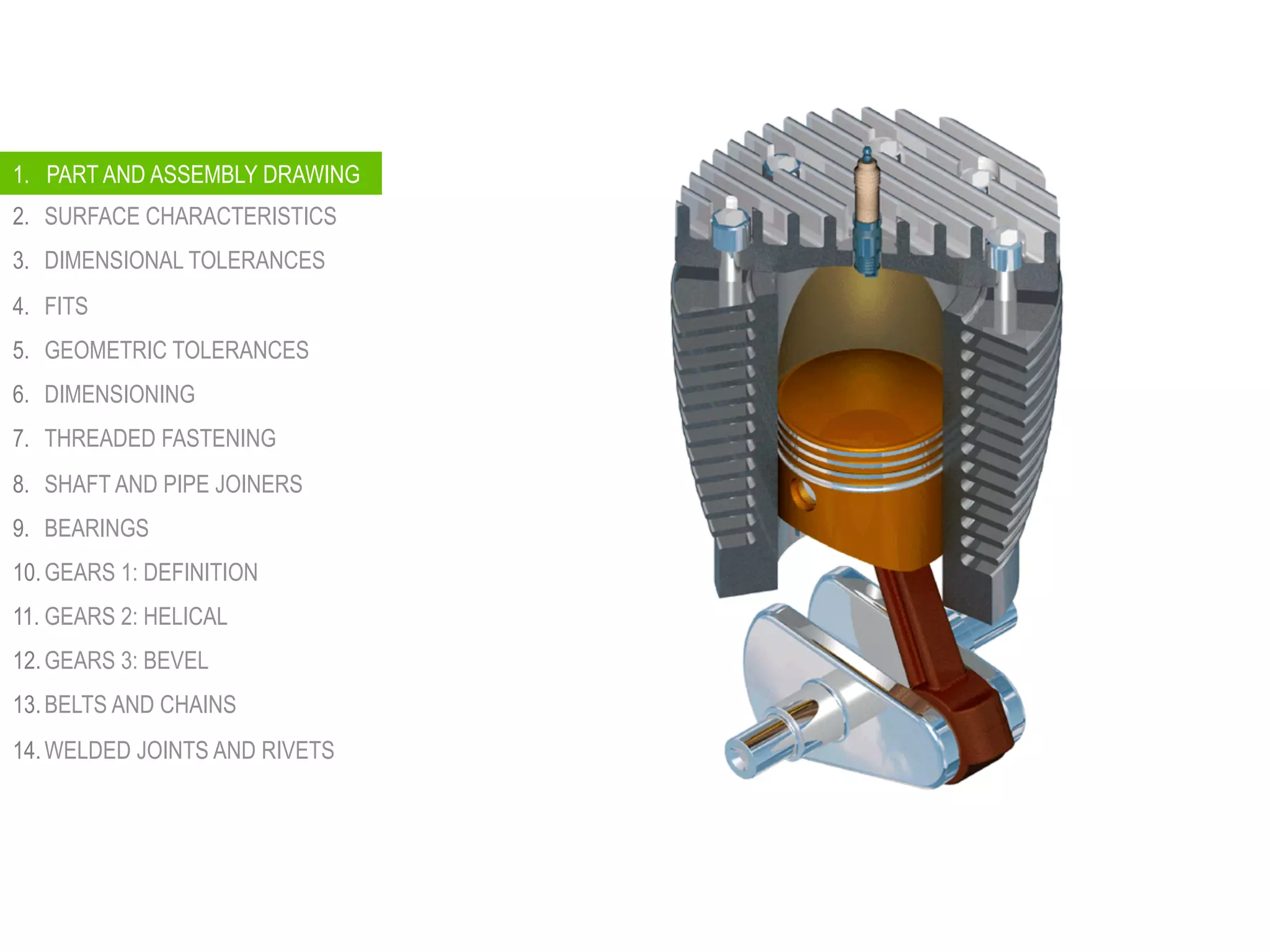
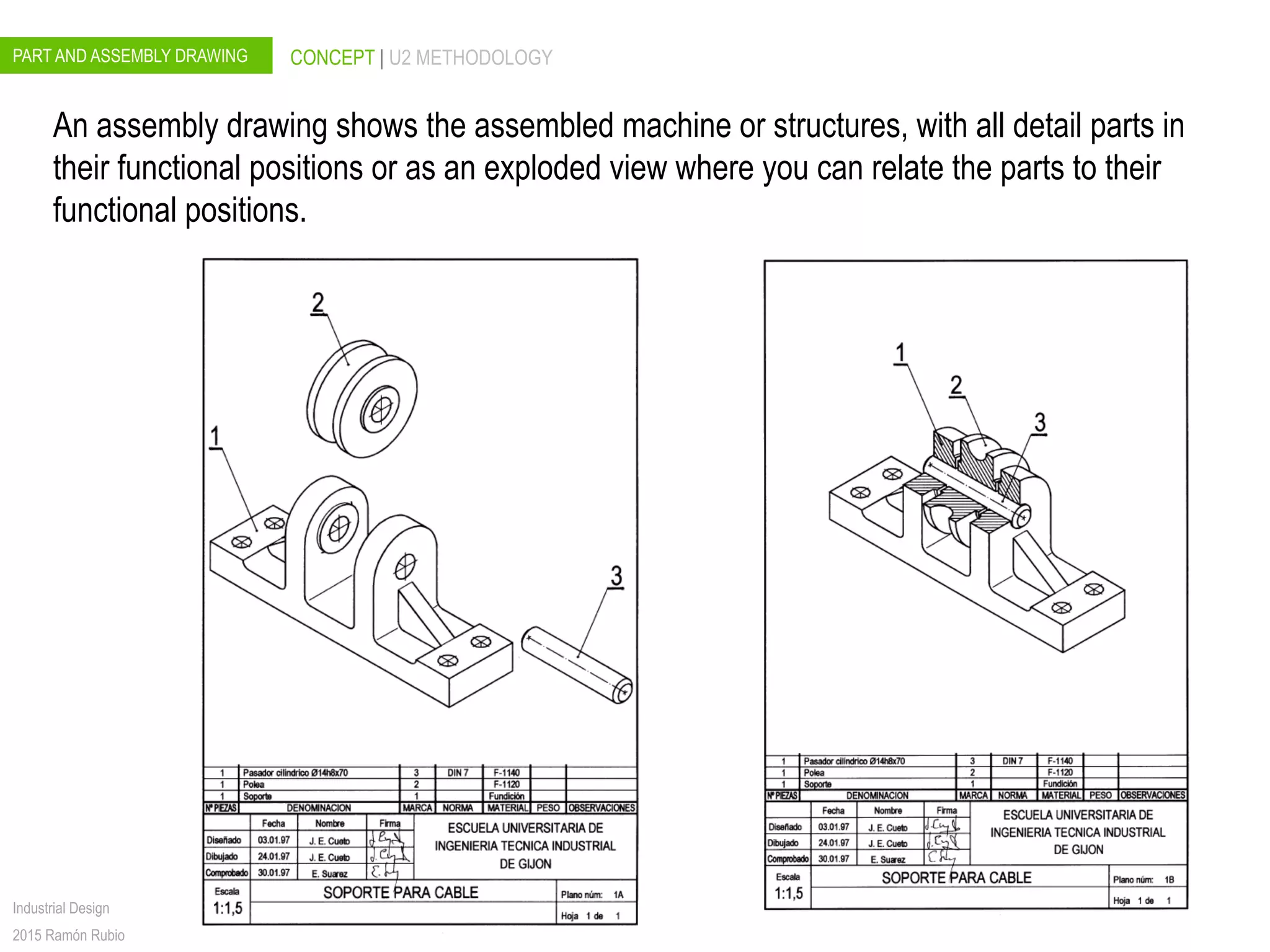
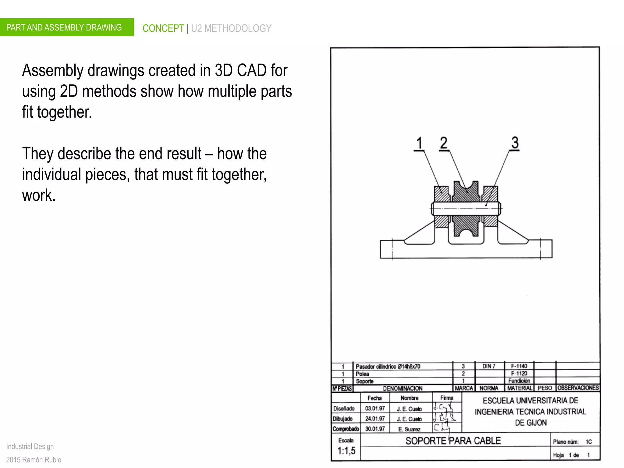
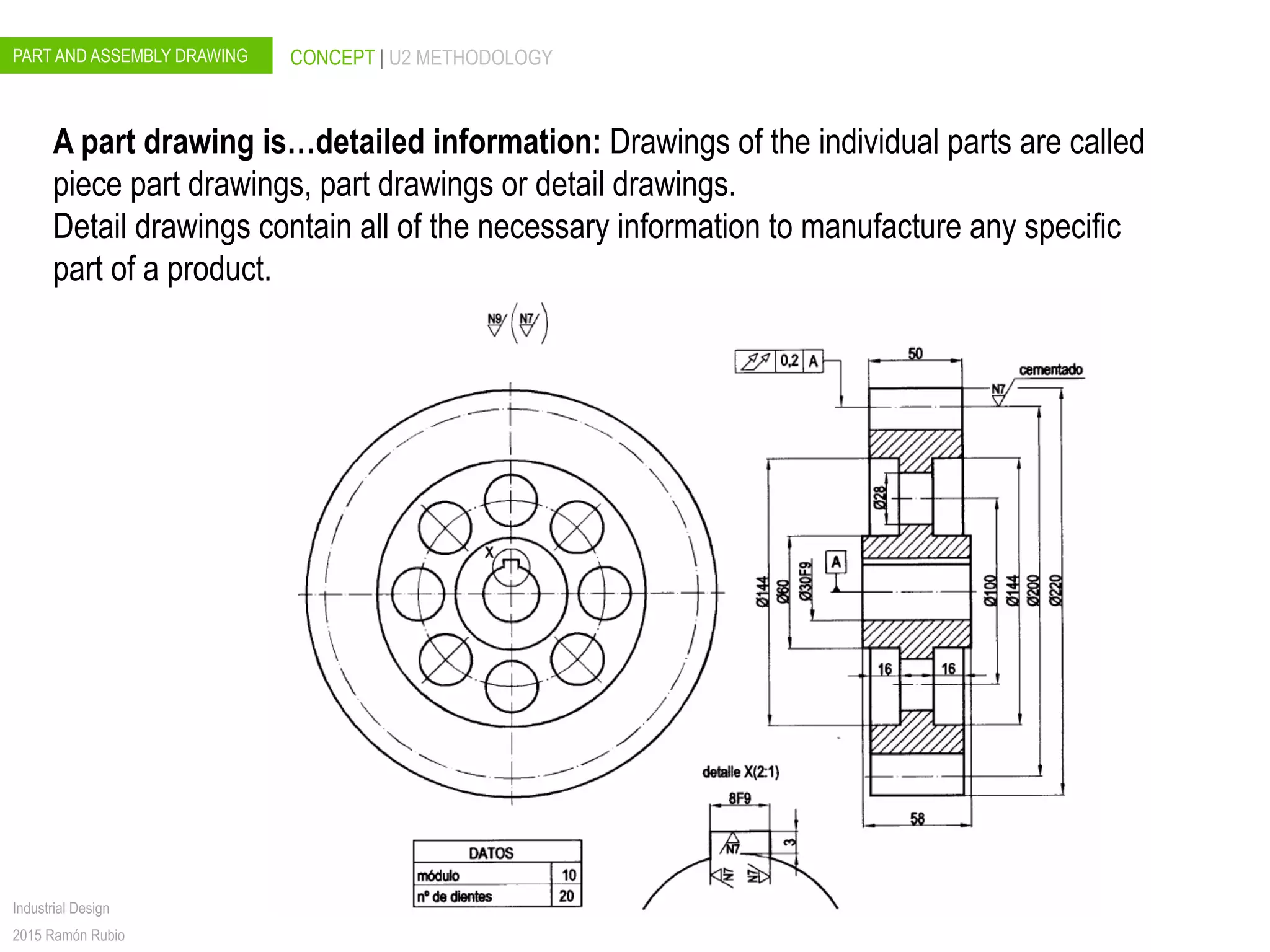
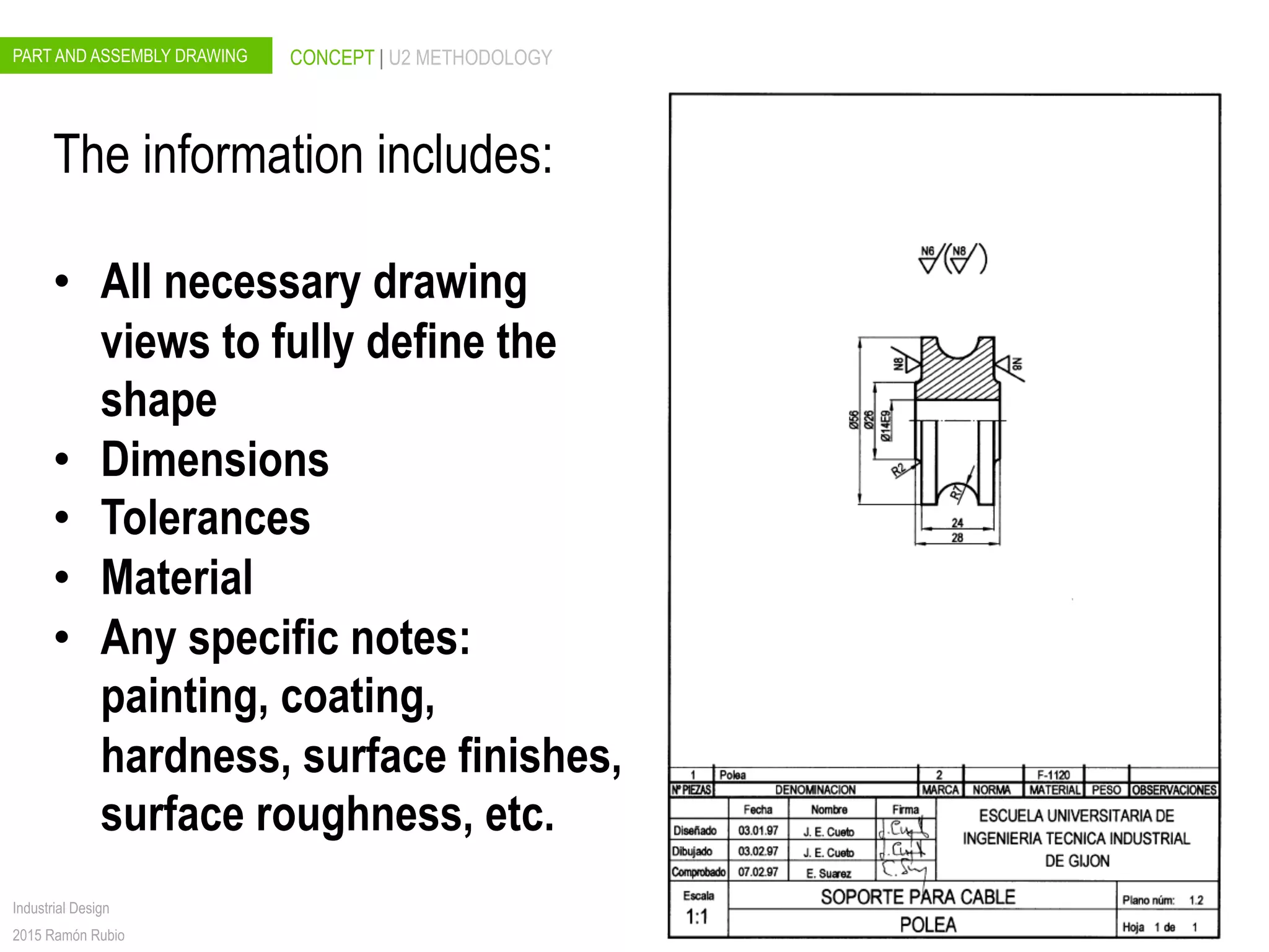
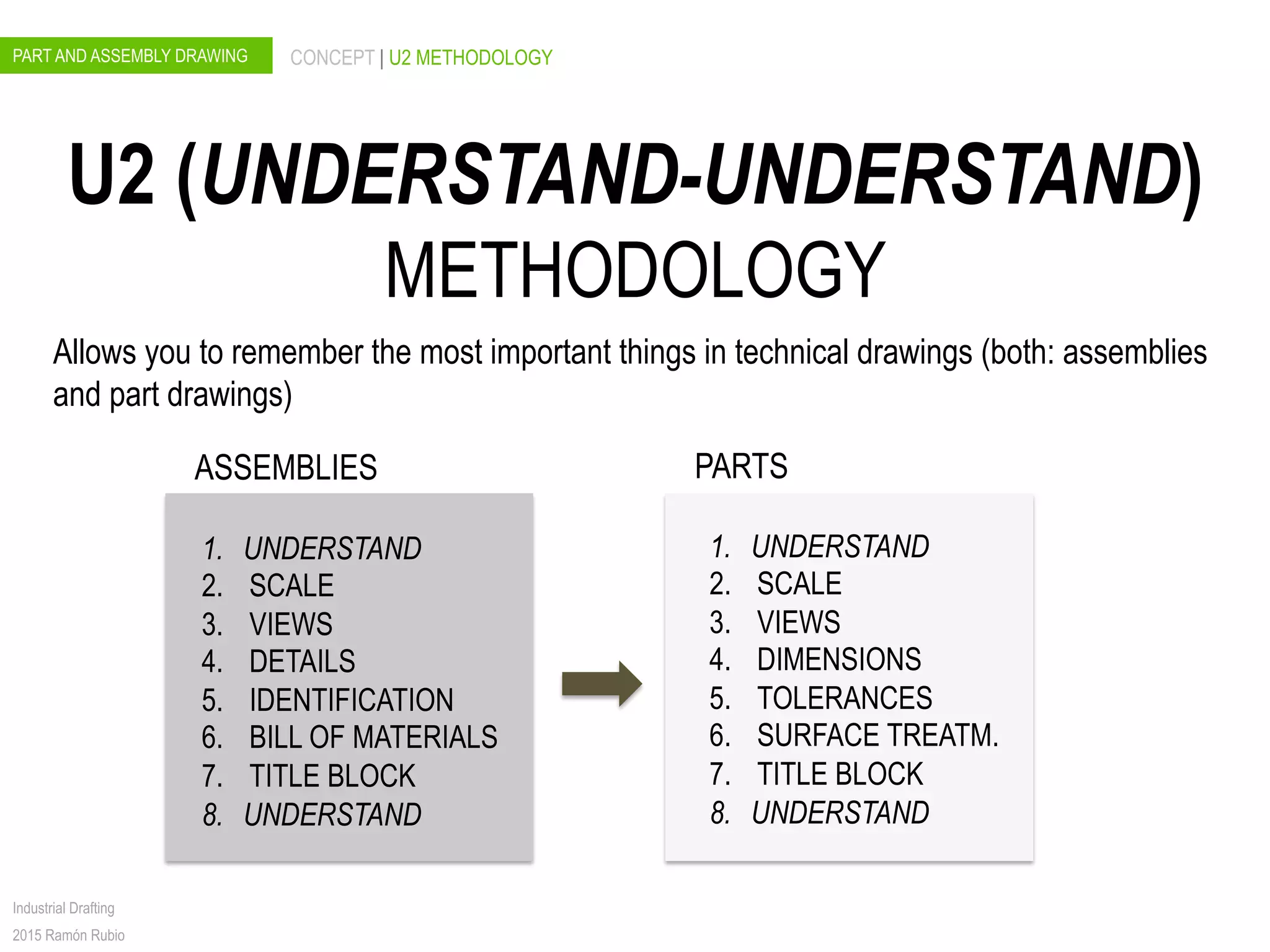

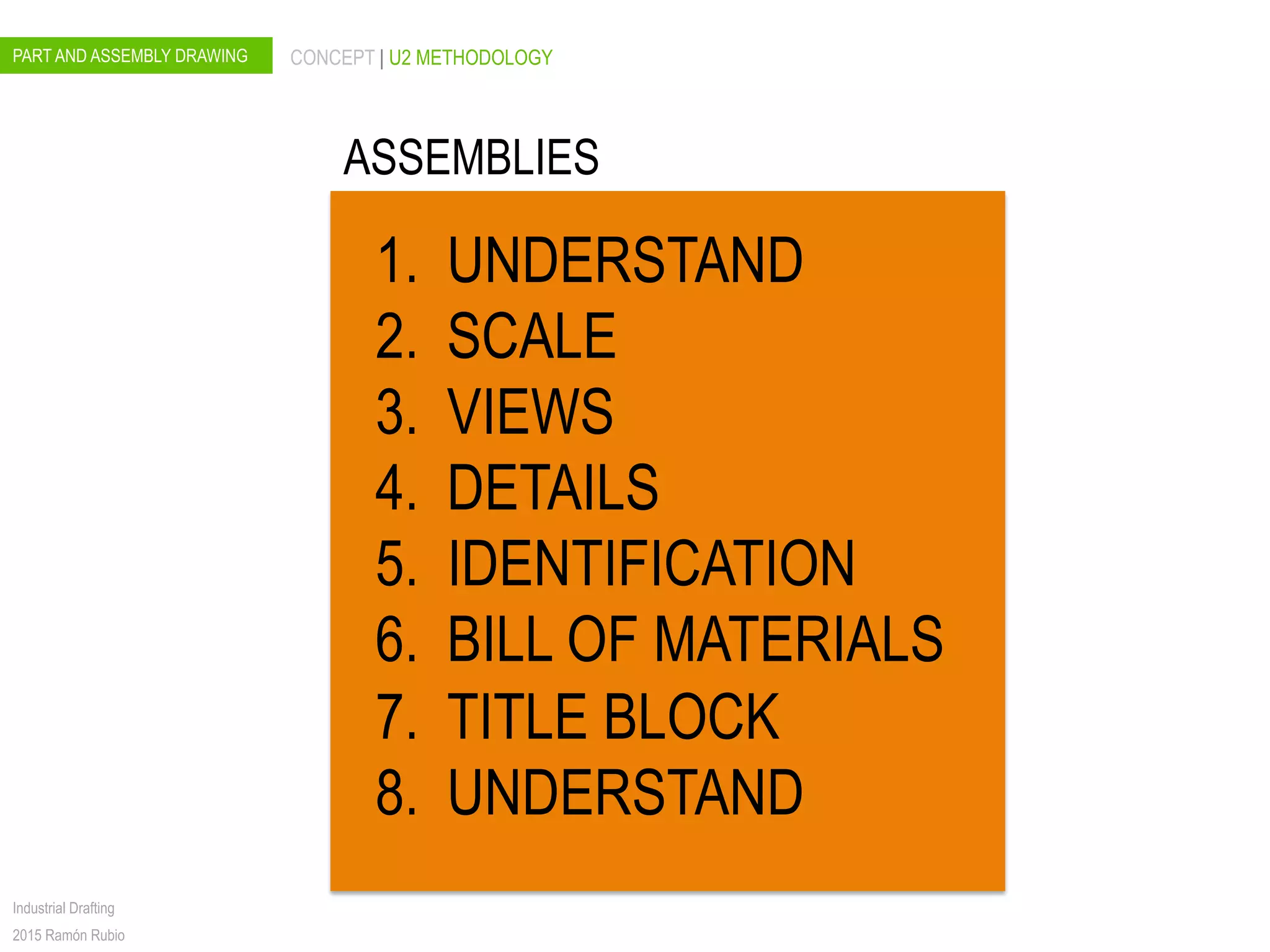
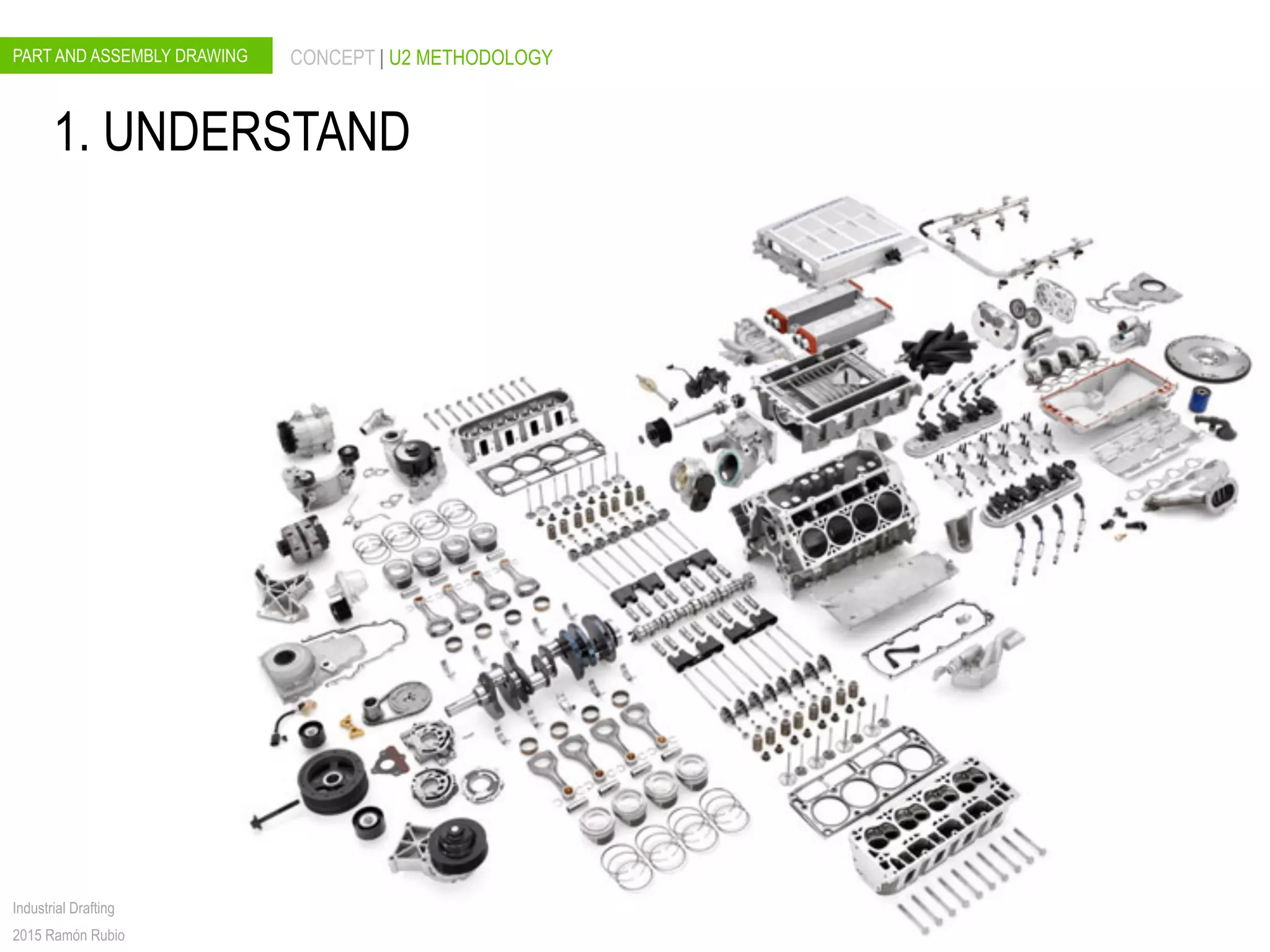

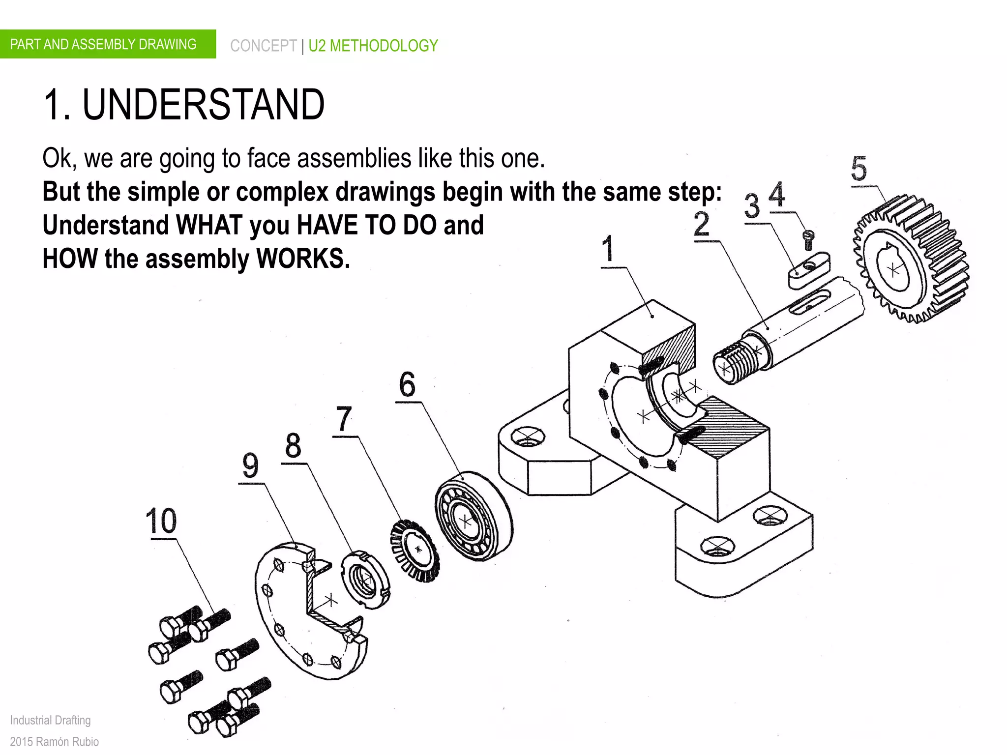
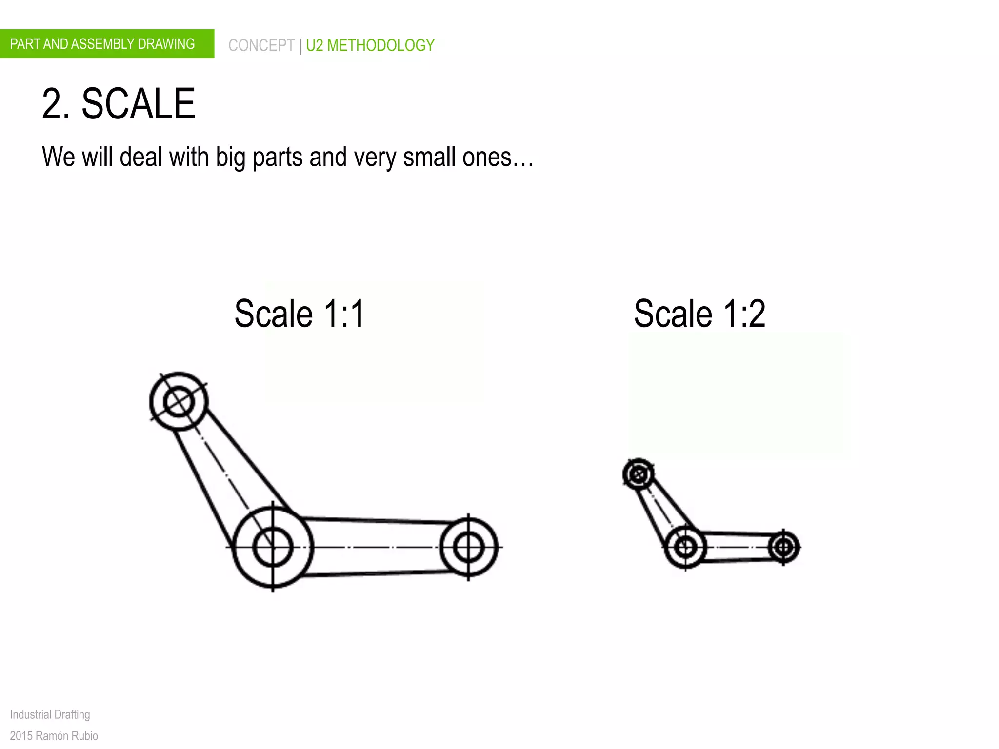
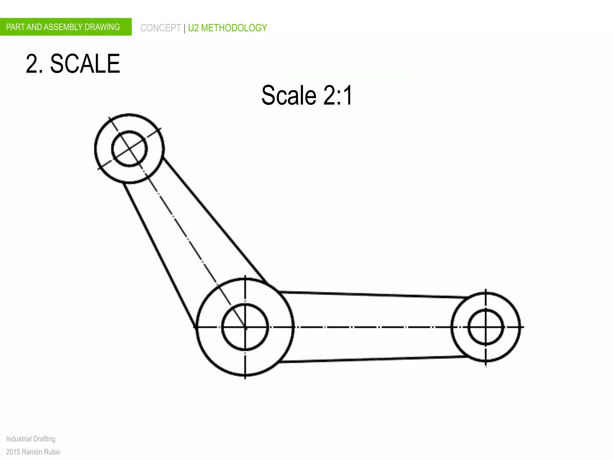
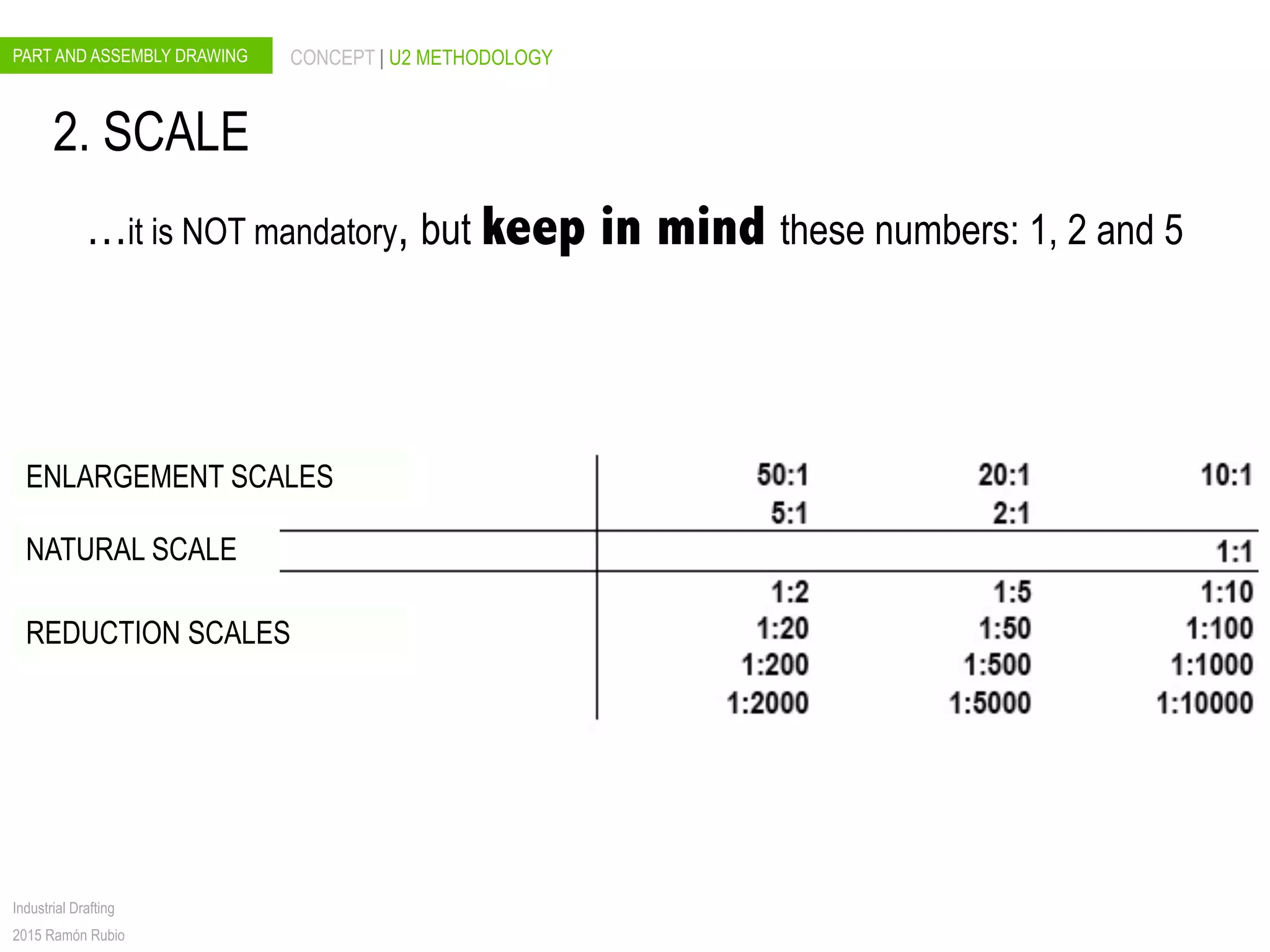
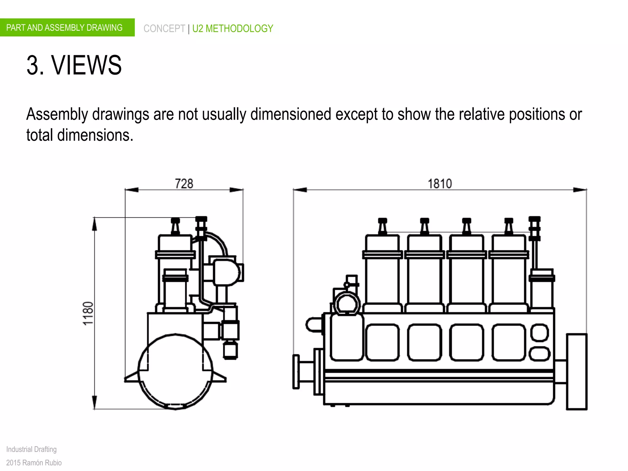
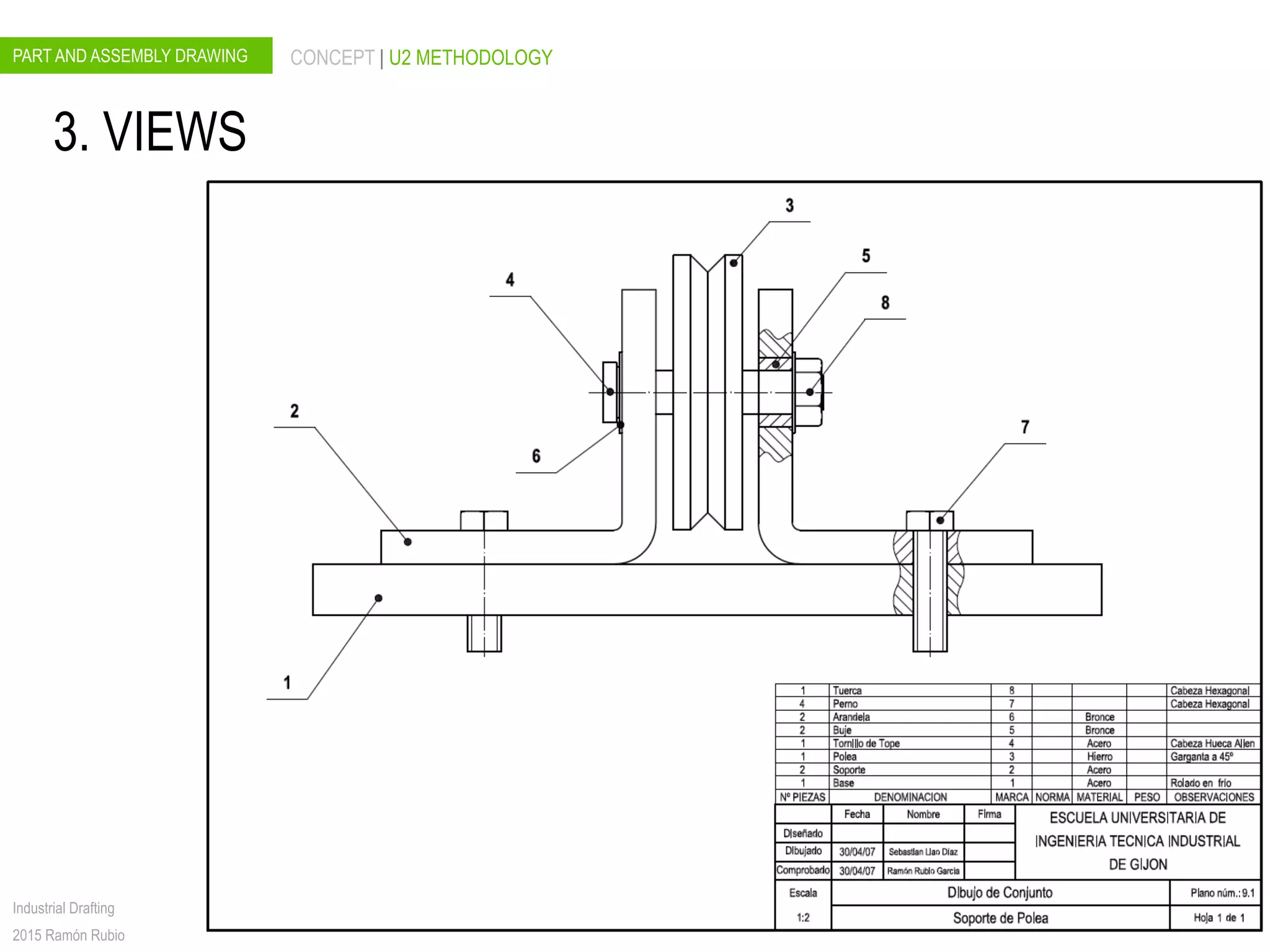
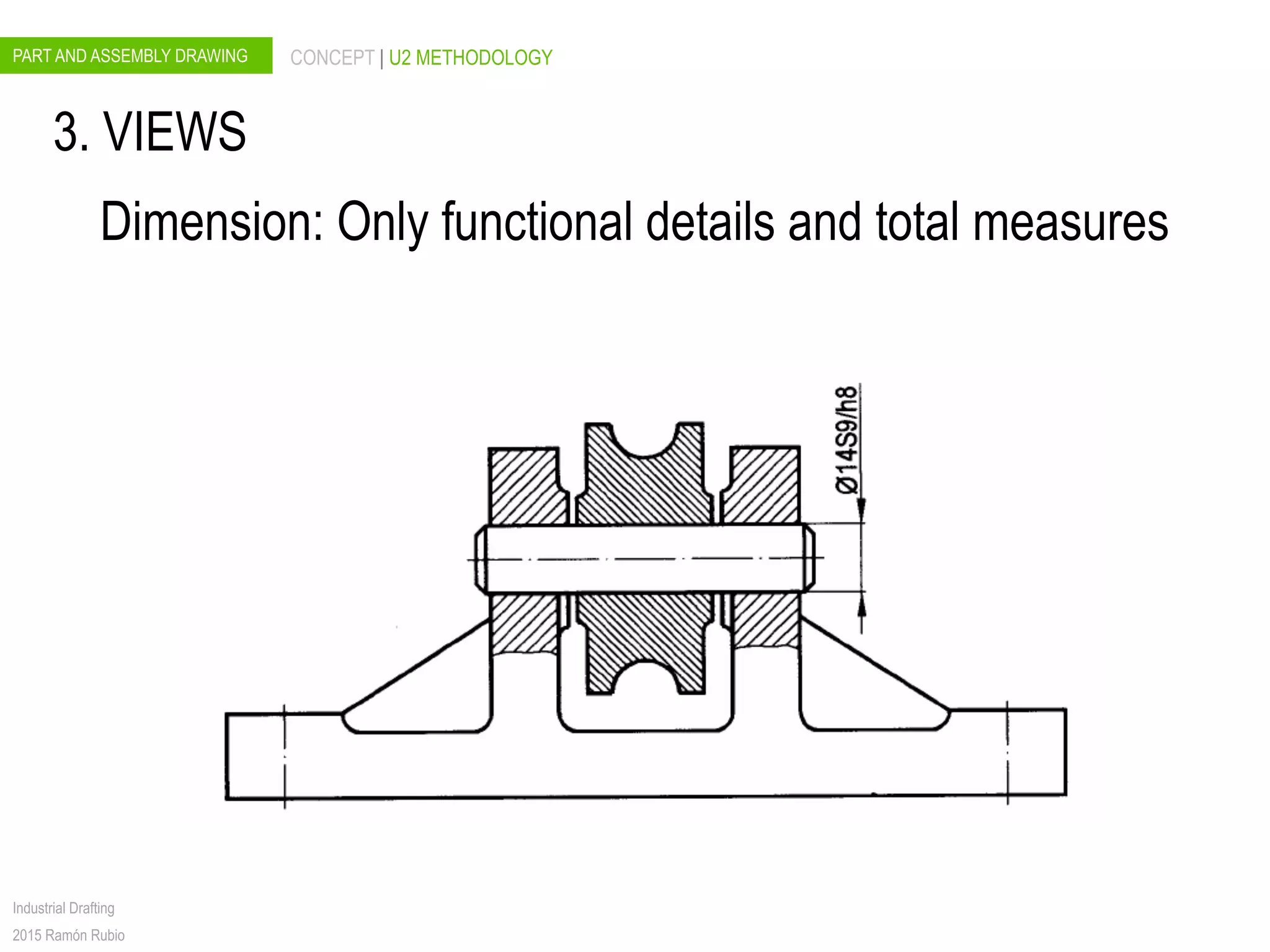
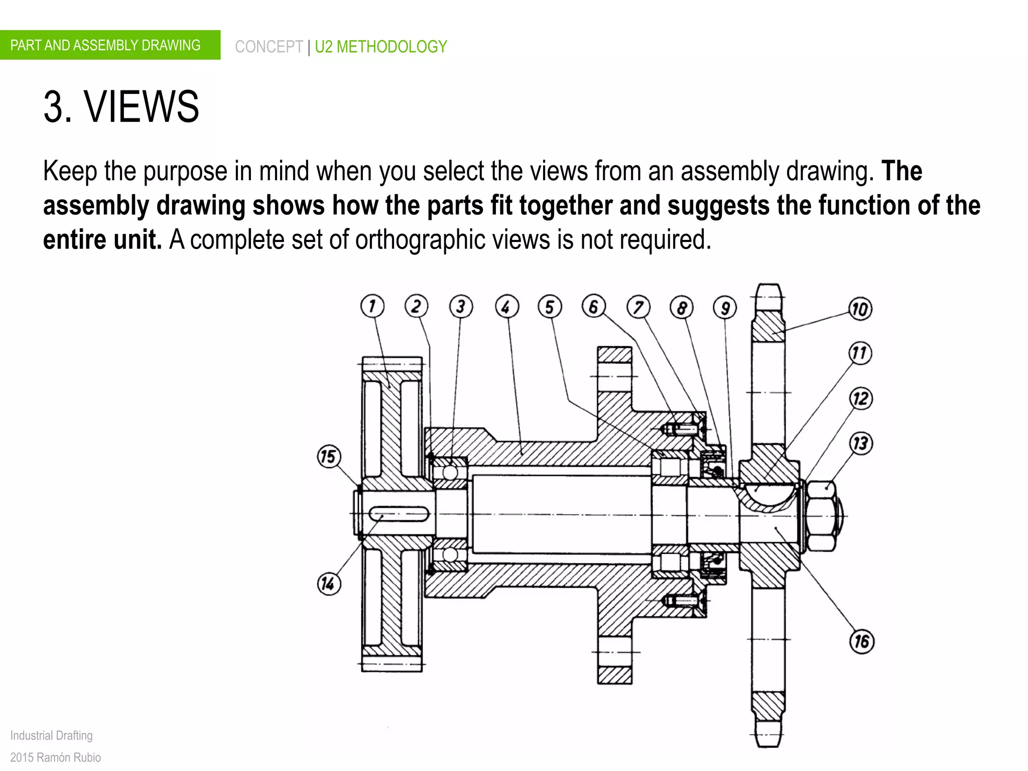
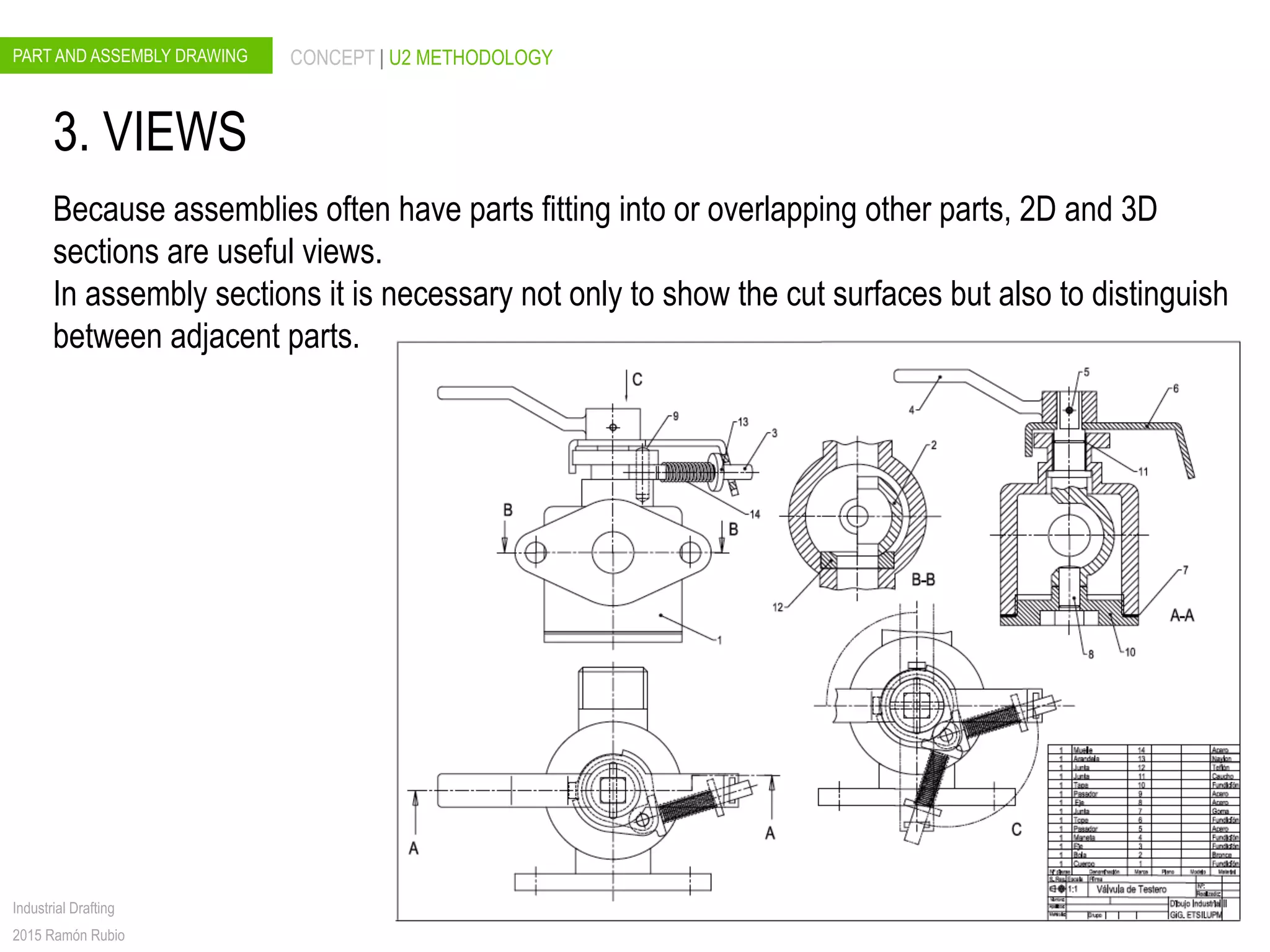
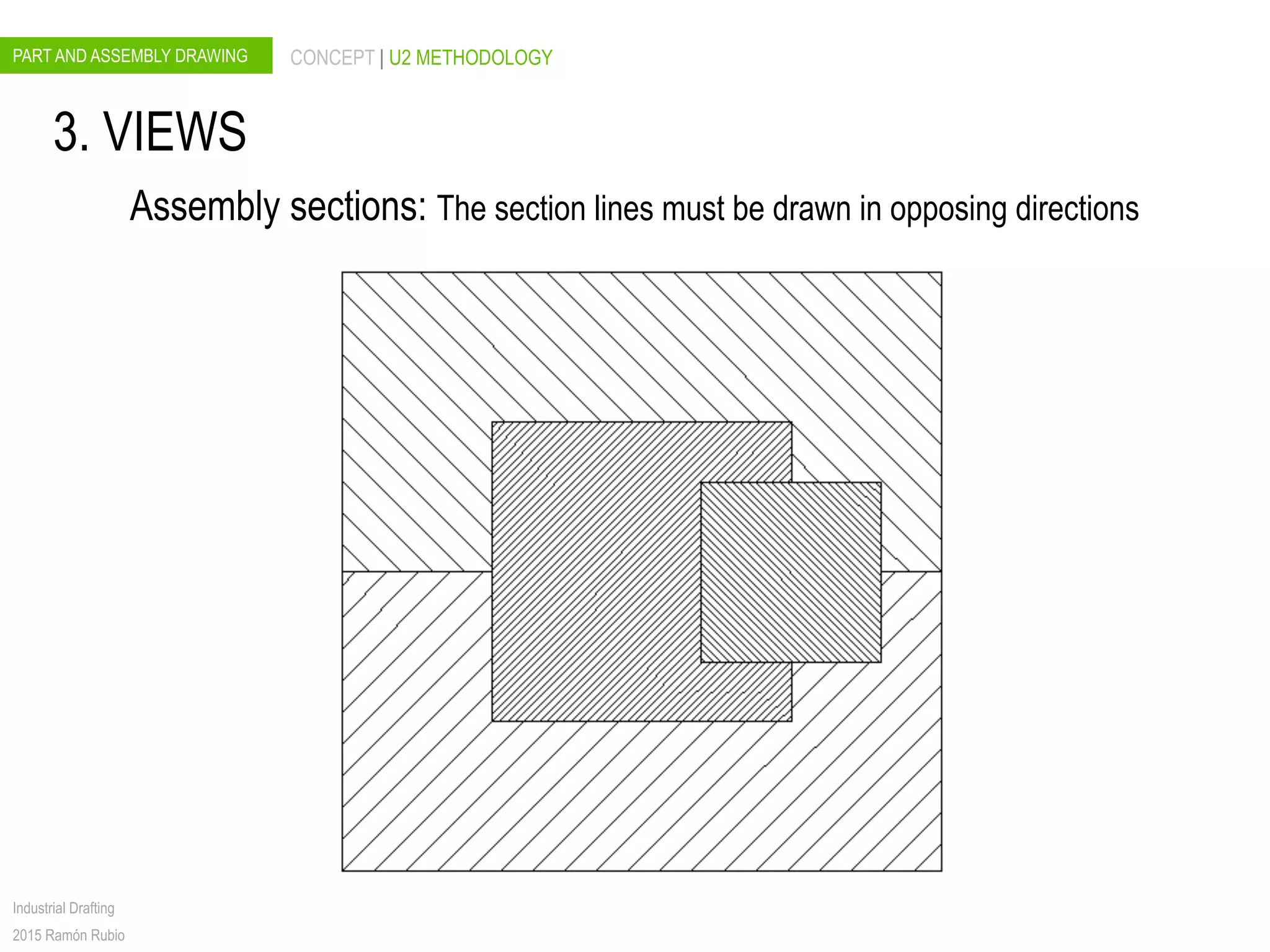
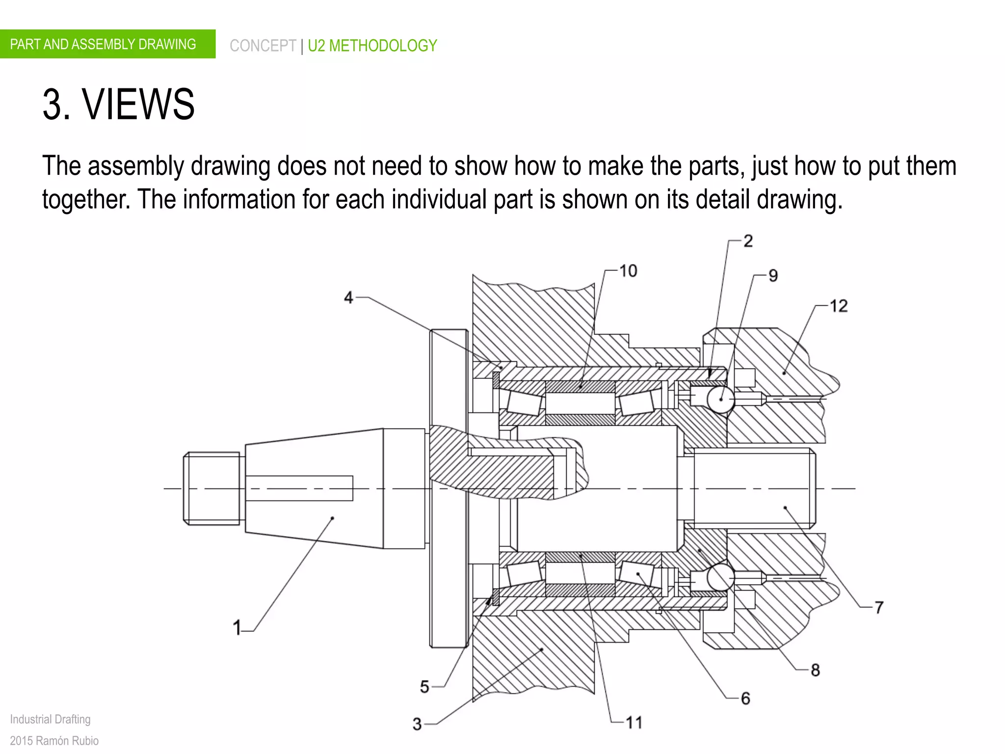
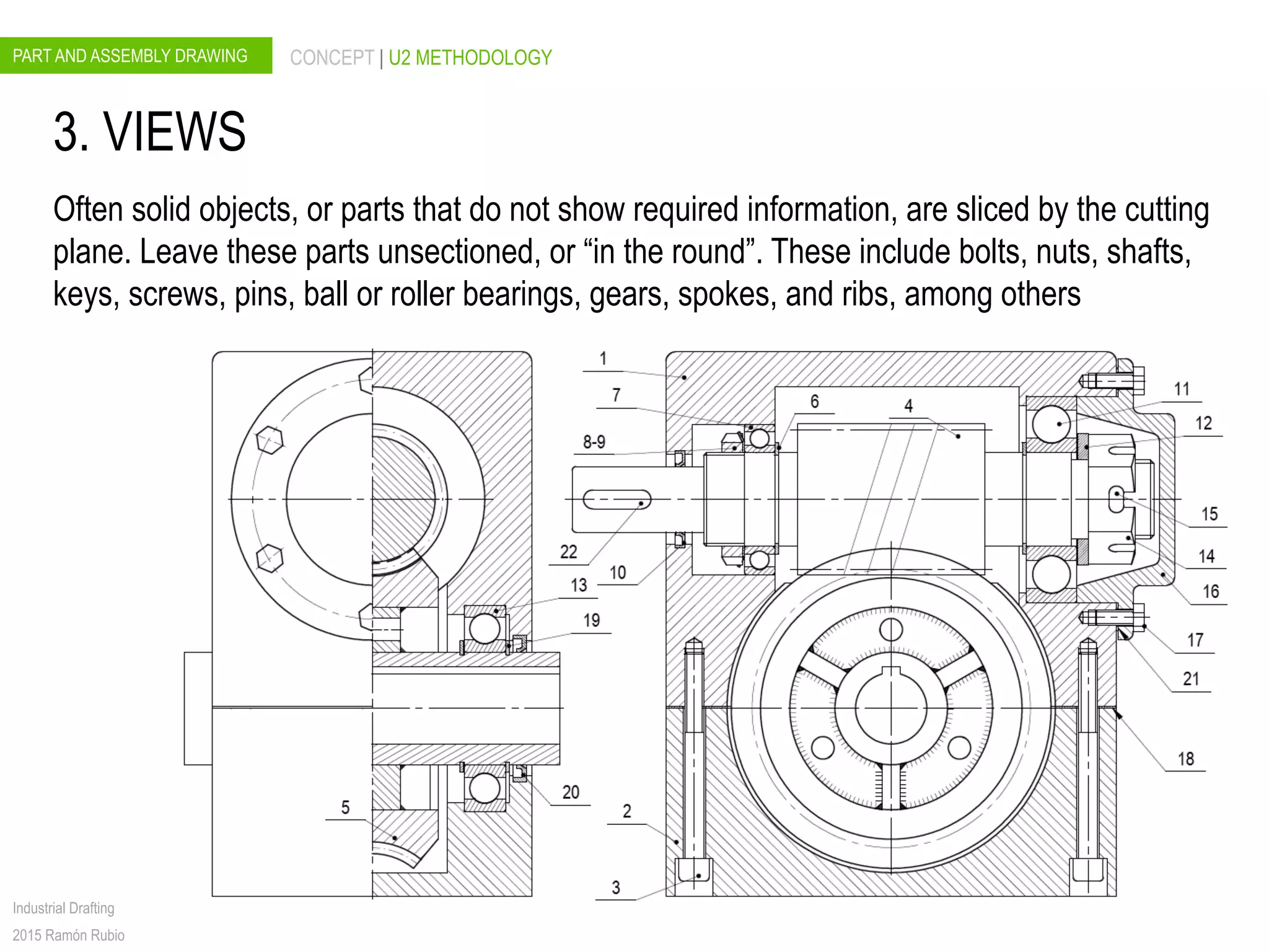
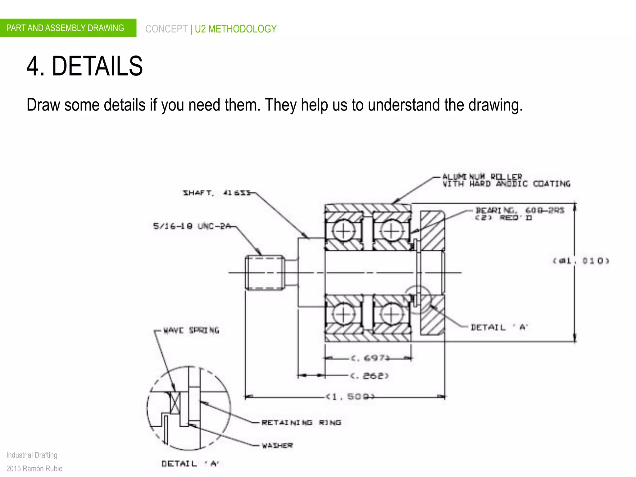
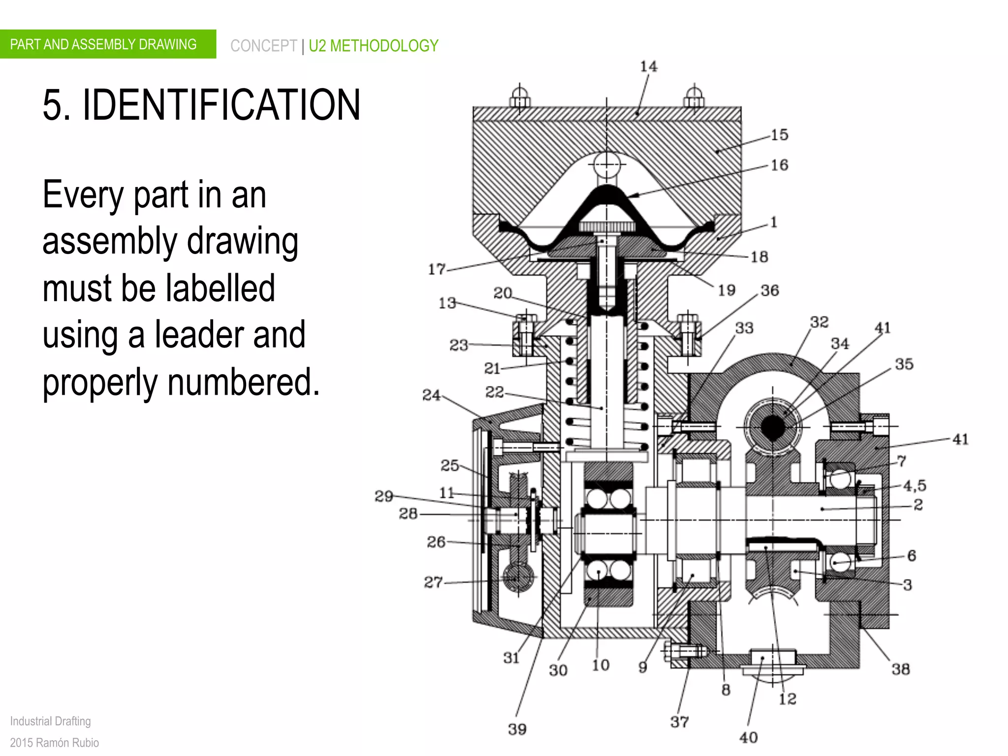
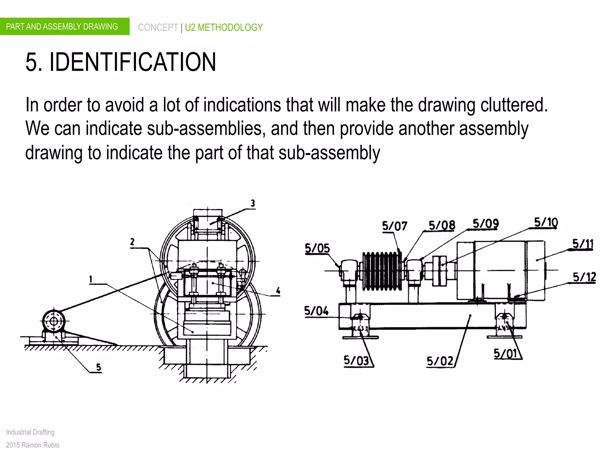
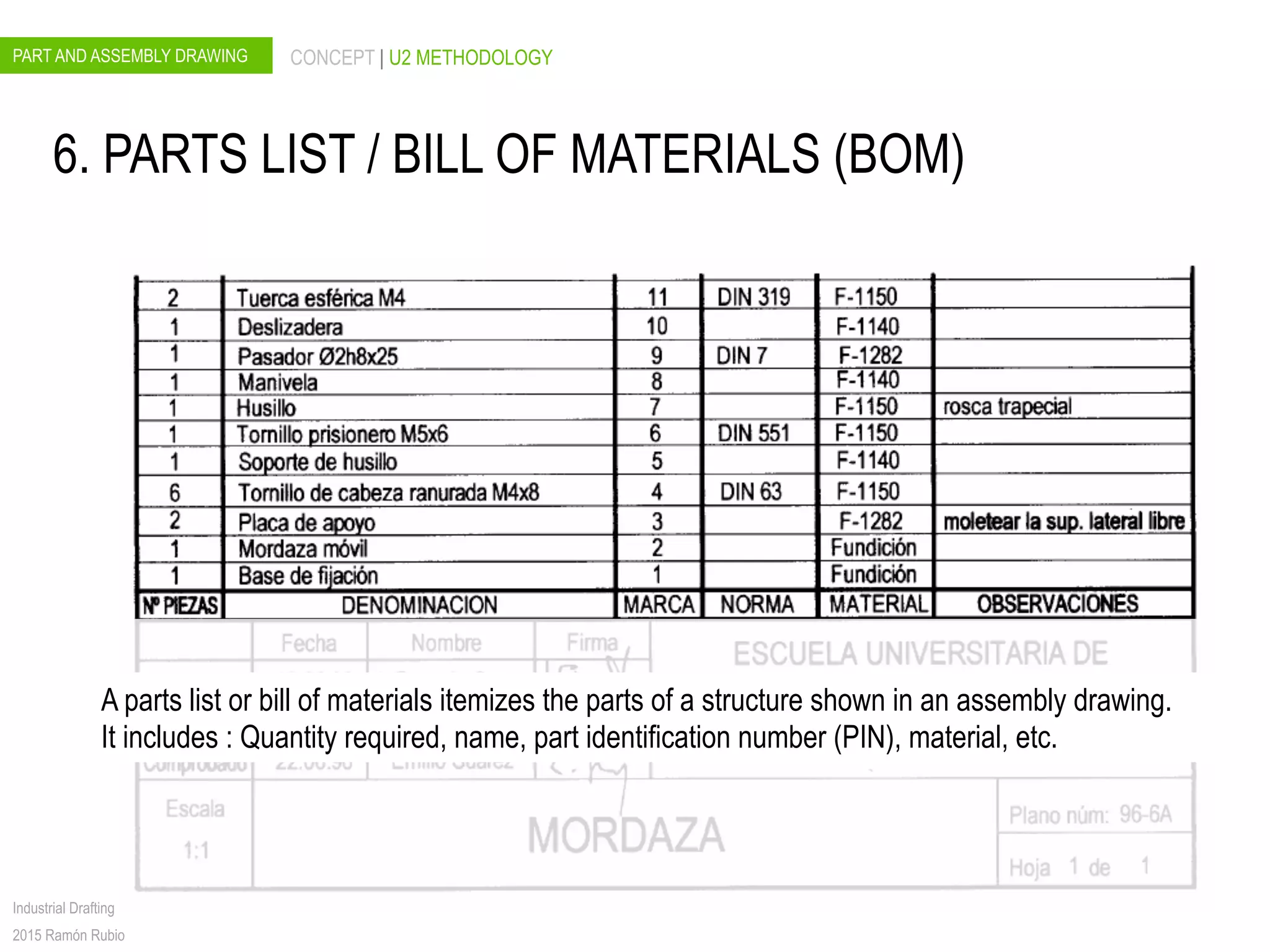
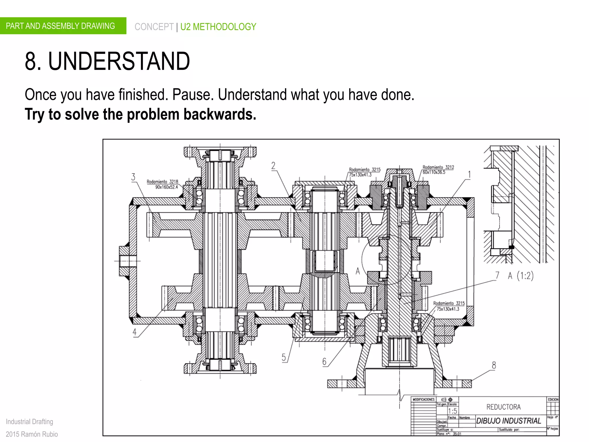
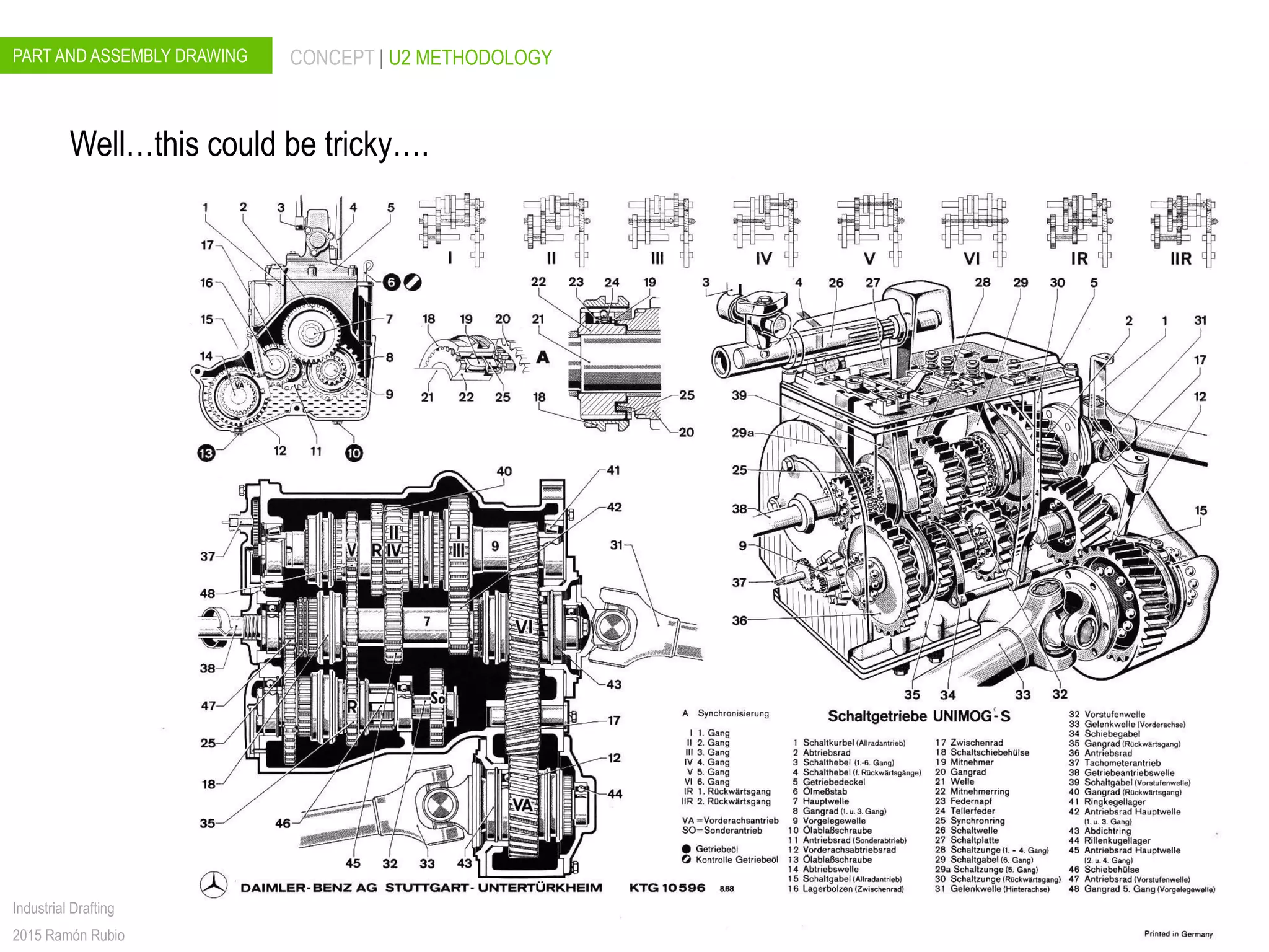
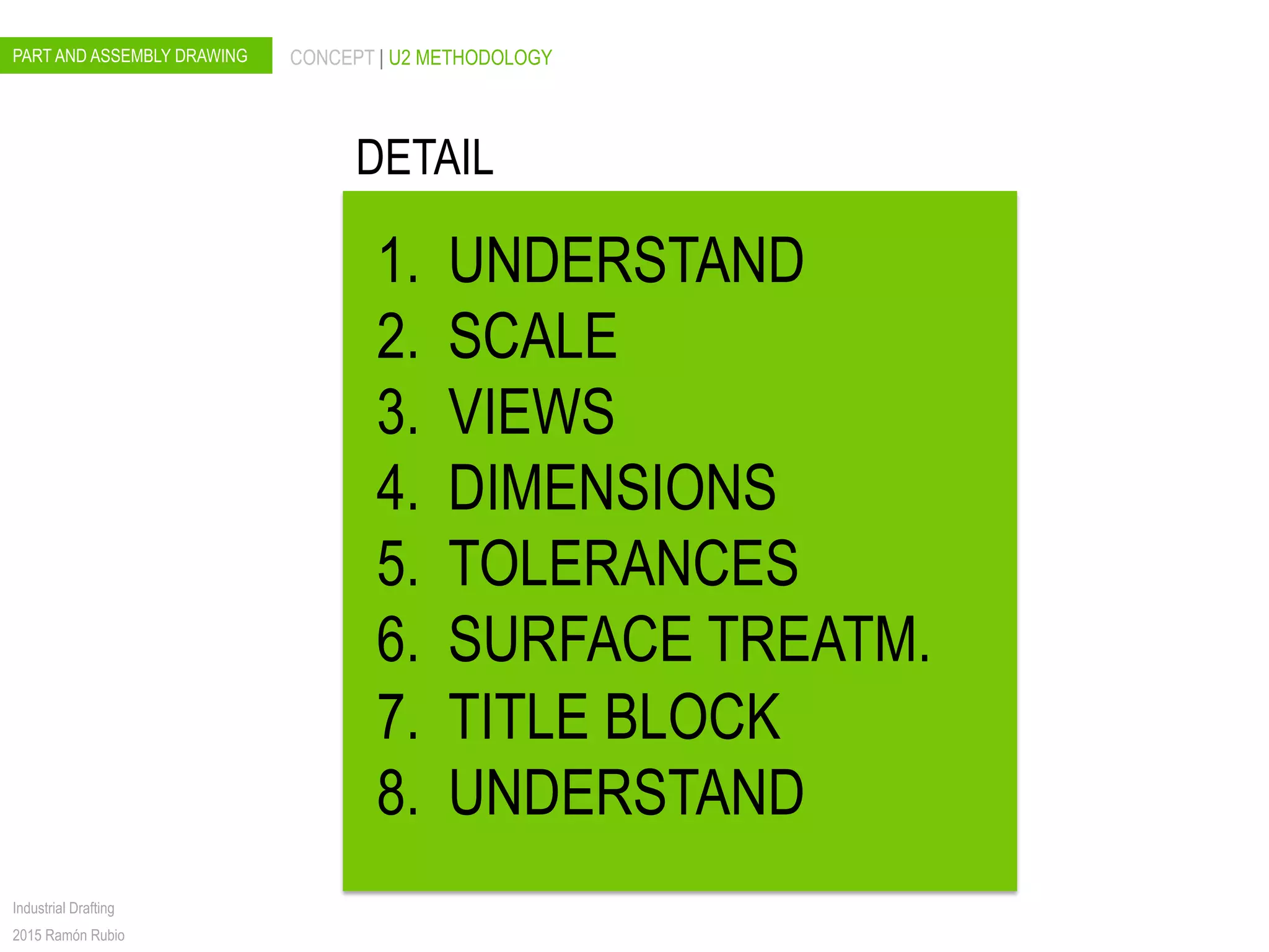
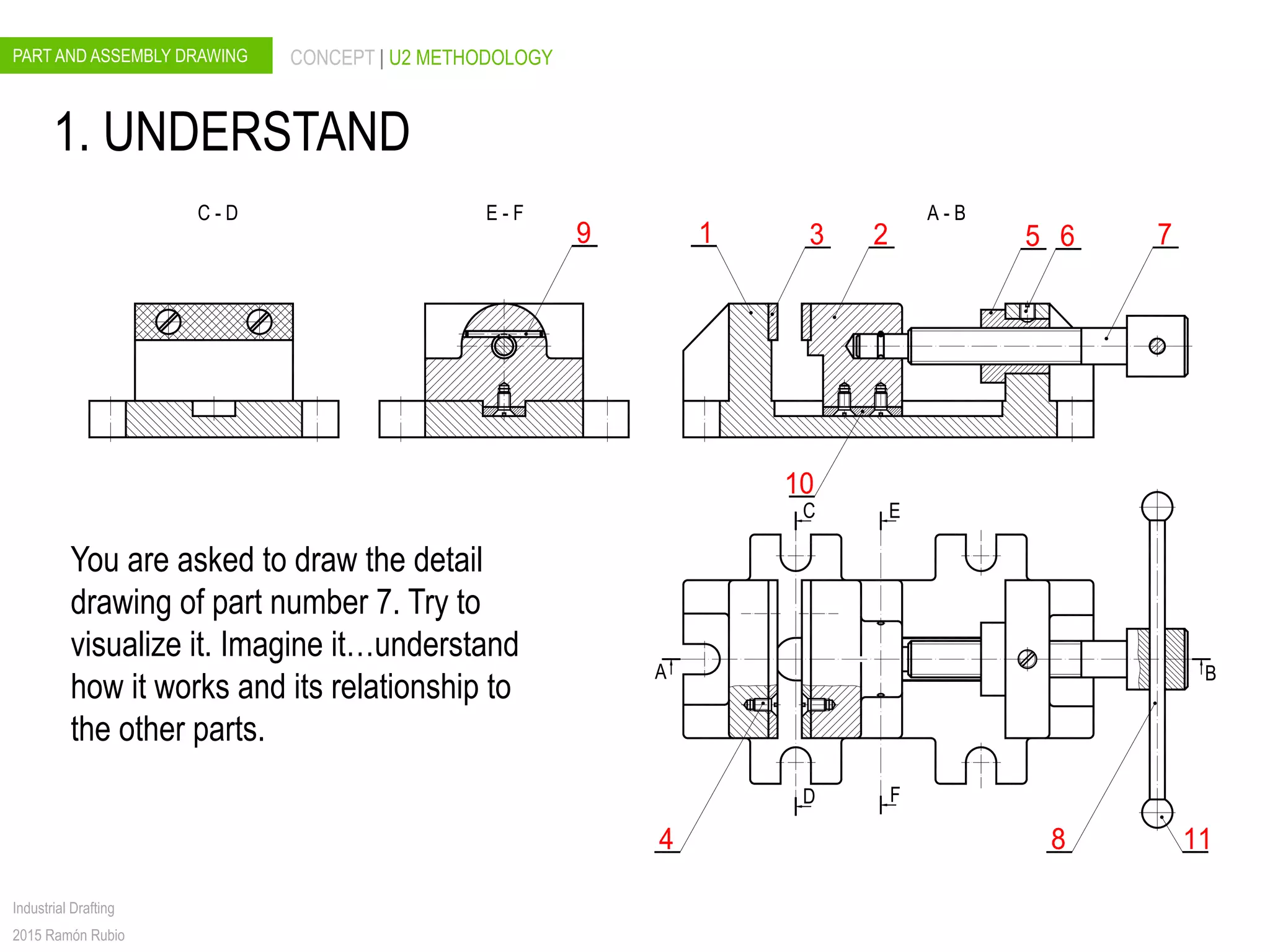

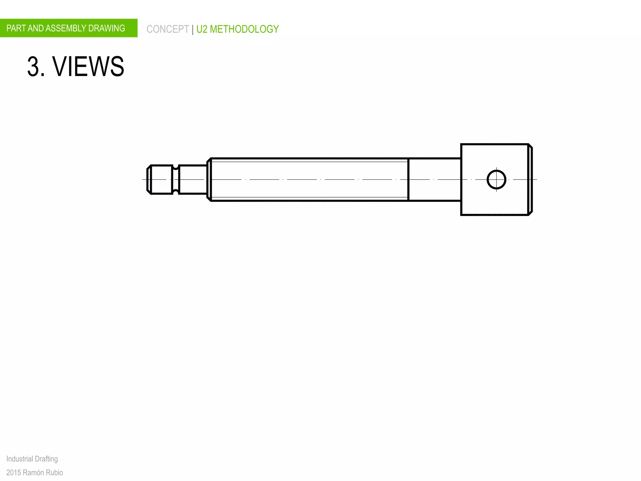
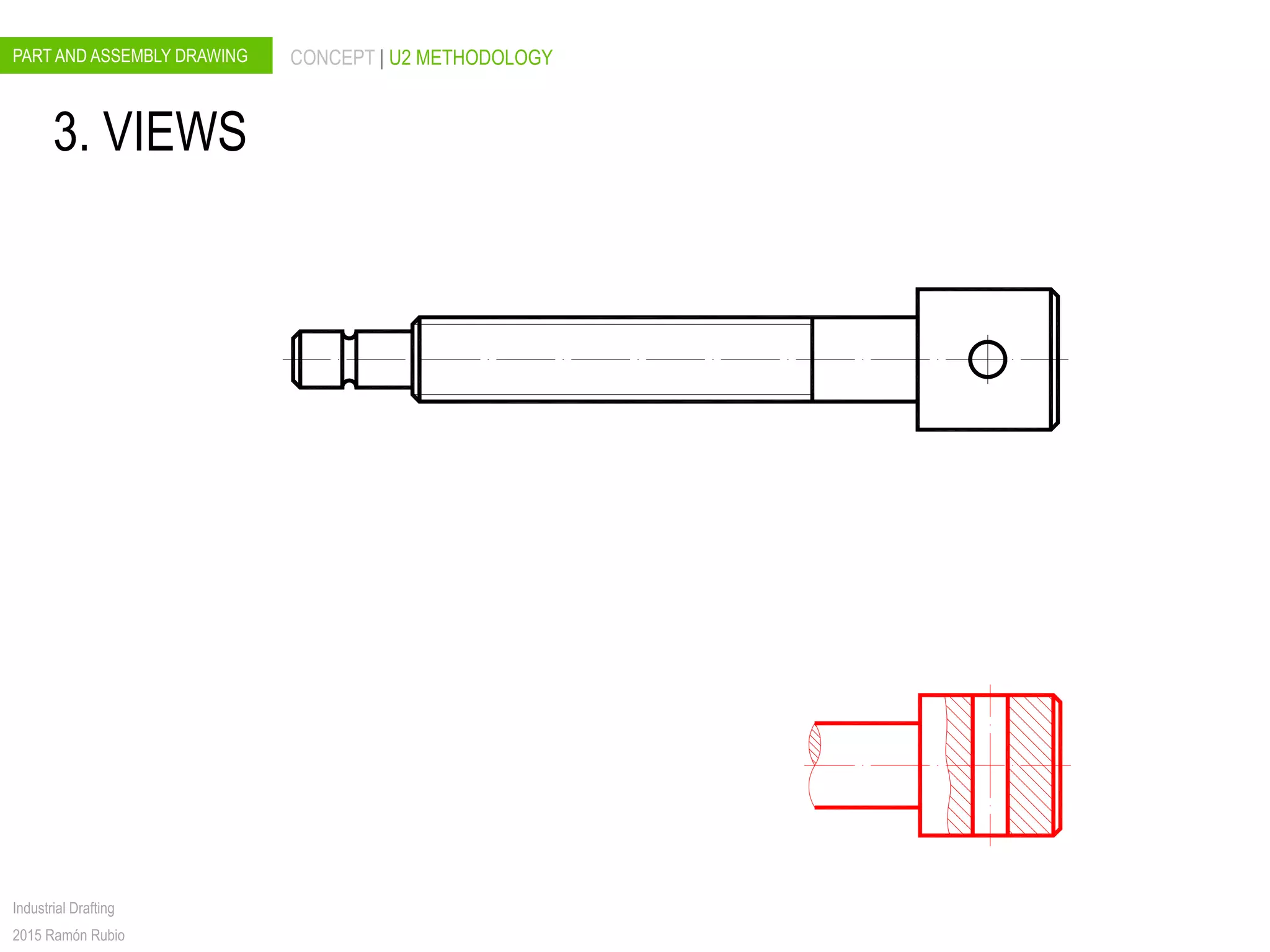
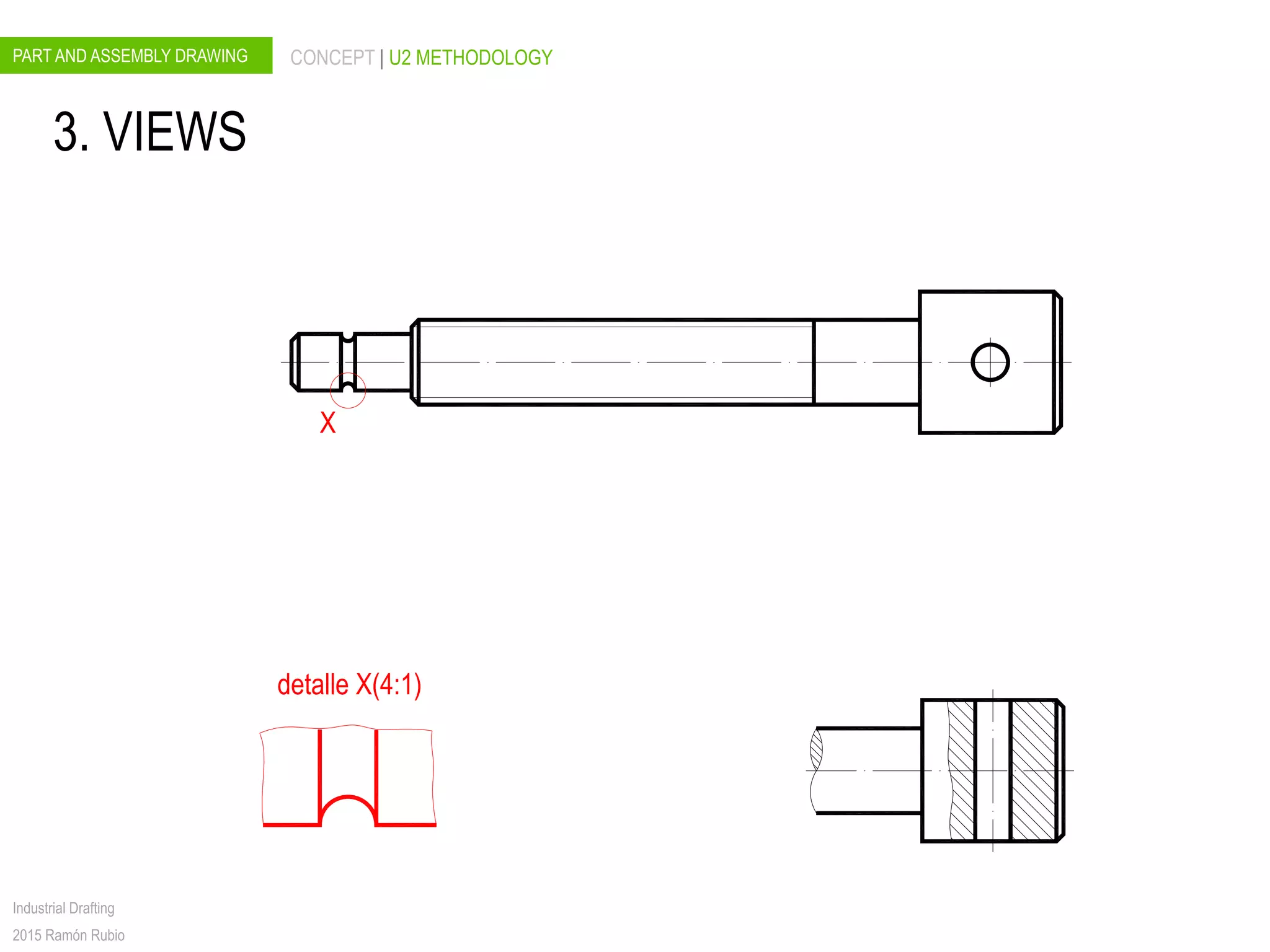
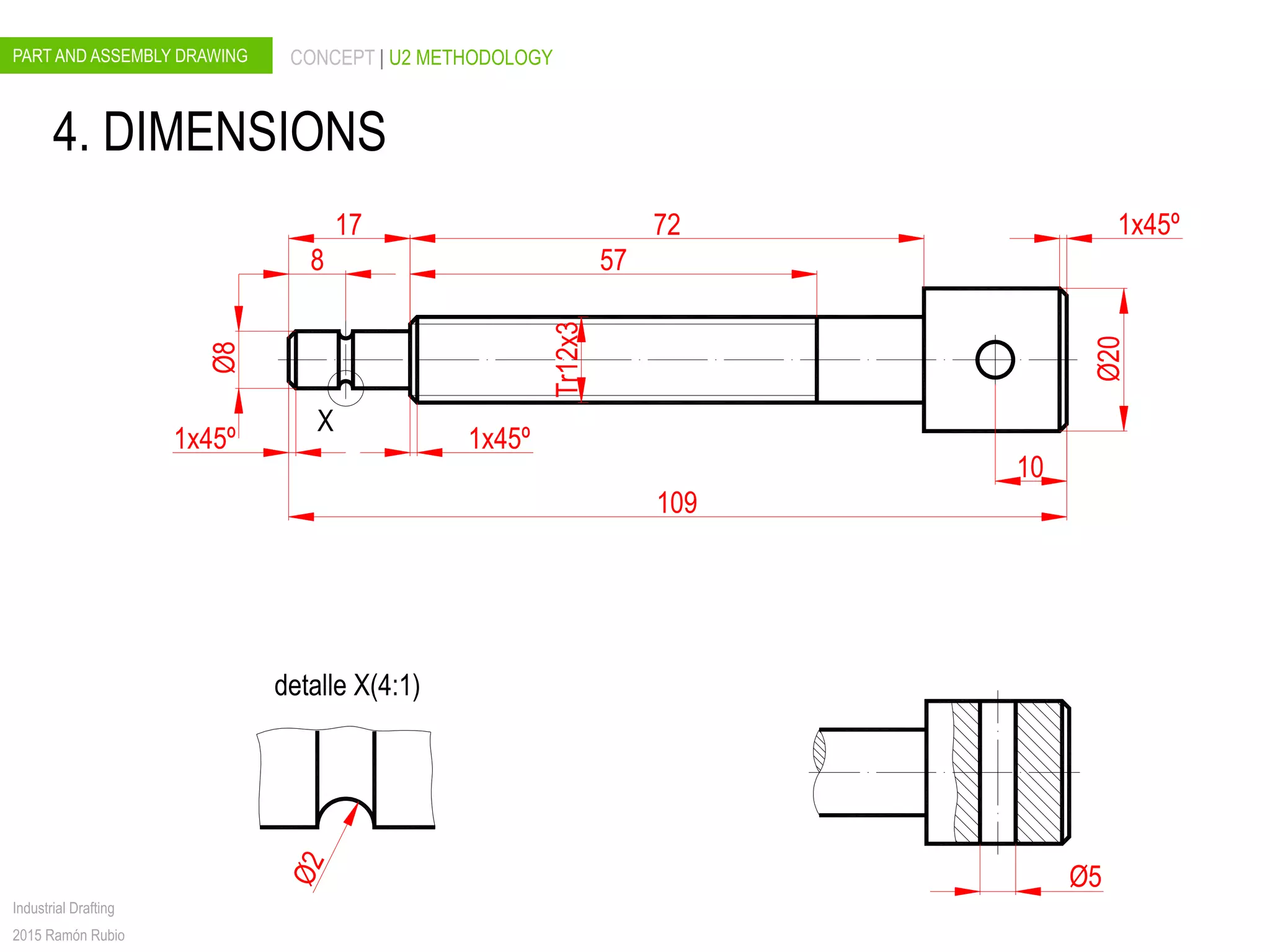
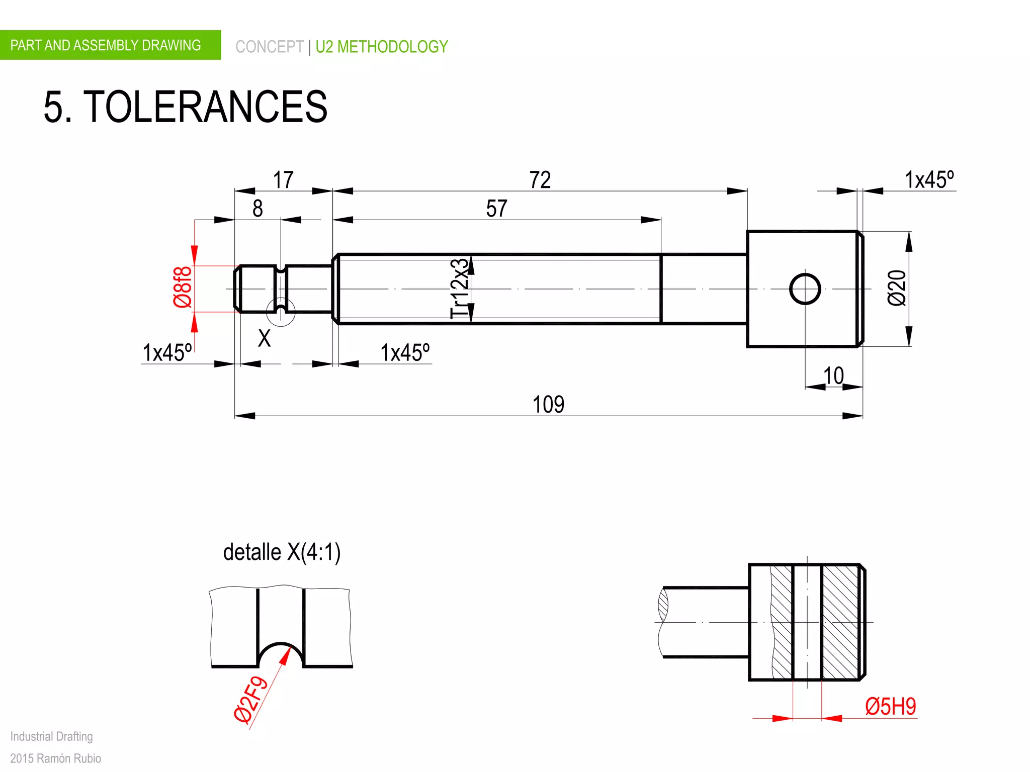
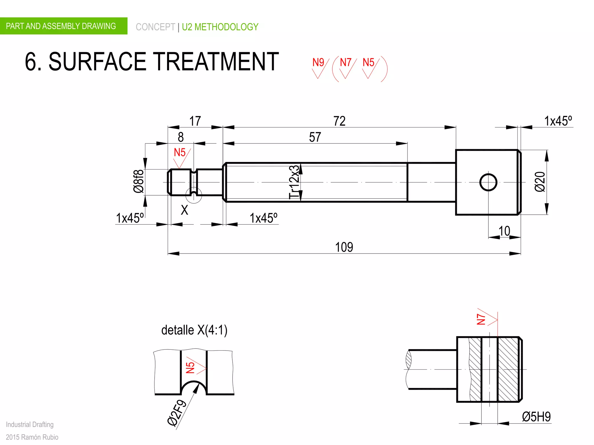
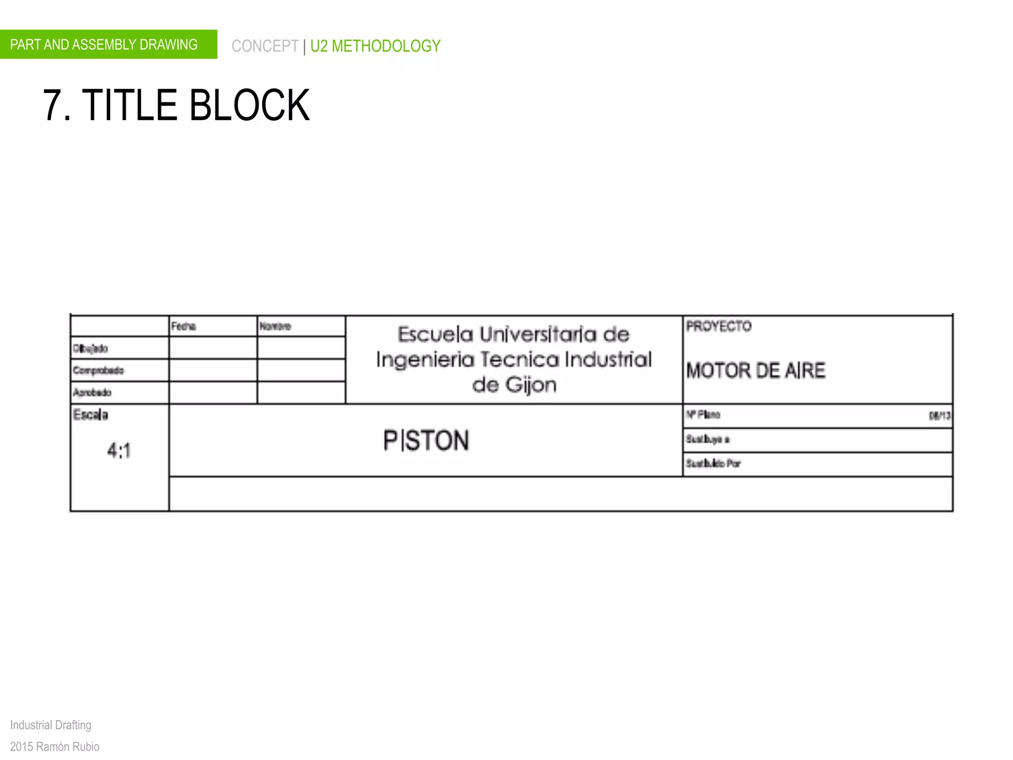
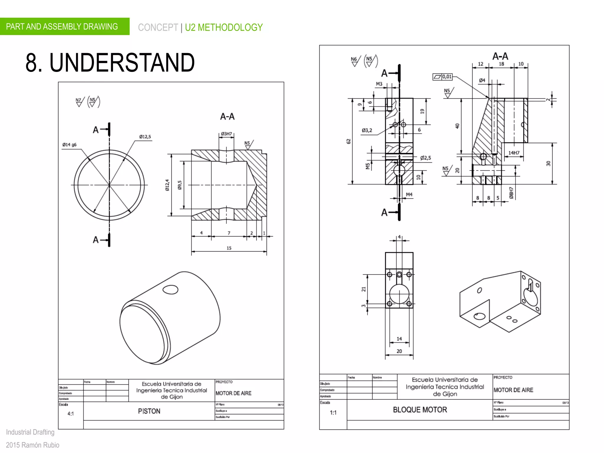


The document discusses key concepts for part and assembly drawings including understanding the assembly, appropriate views and details, part identification, bills of materials, and title blocks. It also outlines steps for creating detail drawings using dimensions, tolerances, surface treatments, and ensuring final understanding. The U2 methodology provides a framework for remembering the important elements of technical drawings.


![[BROCHURE] Italy Tour Project | @SlideON](https://cdn.slidesharecdn.com/ss_thumbnails/brochure8-251215152319-2805af68-thumbnail.jpg?width=640&height=640&fit=bounds)


![Chapt_4[1].ppt very interseting and important](https://cdn.slidesharecdn.com/ss_thumbnails/chapt41-251208222956-7cf5e0fa-thumbnail.jpg?width=640&height=640&fit=bounds)
