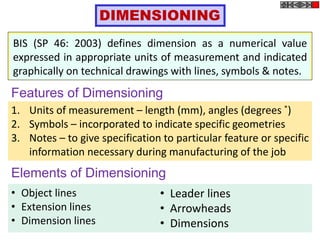
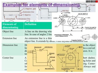
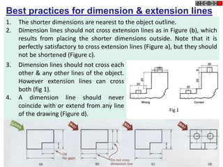
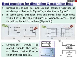
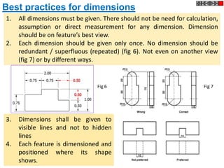
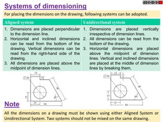
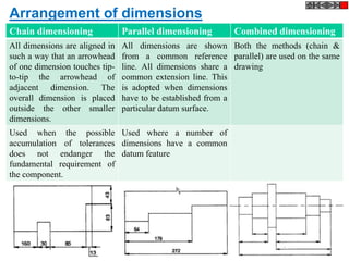
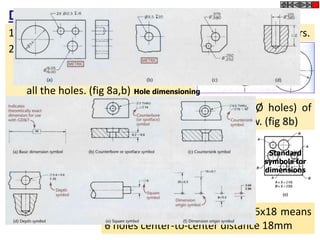
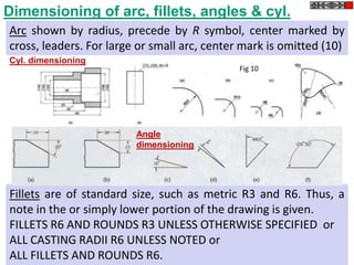
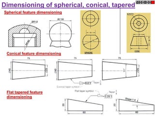
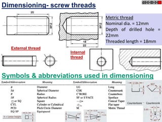
SlideShare a Scribd company logo
L-2
ED-ME111
Dr. Poonam Kumari
LETTERING
Writing text on a drawing (e.g. titles, dimensions, scales)
using letters which can be alphabets, numerals, symbols or
punctuation marks to convey detailed information.
Features of Lettering
1. Legibility, uniformity, ease, rapidity of execution and
reproducibility
2. No ornamental or artistic and cursive style of letter
3. Letters should be distinguishable from each other in order
to avoid any confusion even in case of slight mutilations
Standard followed
IS 9609 (Part 0): 2001 & SP46: 2003 (lettering for technical
drawings). This BIS standard is based on ISO 3098-0: 1997
Types of Lettering
• Single stroke - Thickness of the line of the letter should be
such as is obtained in one stroke of the pencil.
Does not mean that the letter should be made in one
stroke without lifting the pencil.
• BIS (SP46:2003) - Gives dimensions for lettering & types
• Type A - Height of capital letter is divided into 14 parts
• Type B – Height of capital letter is divided into 10 parts
Both types can be Vertical or Inclined at 75˚ to the horizontal
Line Width of Type A ˂ Type B
• Double stroke- When more thickness is given to single stroke
letters, it is known as double stroke or gothic letters.
Basic Strokes
1 1 2
3
“I” letter “A” letter
1
2
3
4 5
6
“B” letter
Examples
Height and width of letters
.
Sl. no Items on a drawing Size (mm)
1 Name of the company 10, 14, 20
2 Drawing numbers, letters denoting section planes 10,14
3 Title of the drawing 7, 10
4 Sub- titles & Headings 5, 7
5 Dimensioning, notes, schedules & material lists 3.5, 7
6 Alteration entries and tolerances 3.5
BIS (SP 46: 2003) has recommended the heights of letters as:
1.8, 2.5, 3.5, 5, 7, 10, 14 & 20 mm
The height-to-width ratio for letters varies between 7 : 5 or 7 : 6
Total height of lowercase
letters equals that of
capital letters.
A & B type
Lettering
BIS (SP46: 2003)
Specifications Type Value Size (mm)
Capital letter height A h 2.5 3.5 5 7 10 14 20
B h 2.5 3.5 5 7 10 14 20
Lowercase letter height A a=(5/7)h - 2.5 3.5 5 7 10 14
B a=(7/10)h - 2.5 3.5 5 7 10 14
Thickness of lines A b=(1/14)h .18 .25 .35 .5 .7 1 1.4
B b=(1/10)h .25 .35 .5 .7 1 1.4 2
Spacing between characters A c=(1/7)h .35 .5 .7 1 1.4 2 2.8
B c=(1/5)h .5 .7 1 1.4 2 2.8 4
Minimum spacing between
words
A d=(3/7)h 1.05 1.5 2.1 3 4.2 6 8.4
B d=(3/5)h 1.5 2.1 3 4.2 6 8.4 12
Minimum spacing between
baselines
A e=(10/7)h 3.5 5 7 10 14 20 28
B e=(7/5)h 3.5 5 7 10 14 20 28
Vertical Capital Letters
and Numerical
Vertical
Lowercase
Letters
Inclined Capital Letters
At 75˚
1. Height of numerator
and denominator =
3/4th of height of non-
fractioned number
2. Spacing between
division bar and
numerator or
denominator should
be such that the total
height of fraction will
be twice of that of
non-fractioned
number
Fraction & Indices lettering
The height of index
is half of height of a
base letter
Few Tips
If you put the central horizontal strokes of the letters B, E, F, and H at mid-
height, they will appear to be below center. To overcome this optical
illusion, draw the strokes B, E, F, and H slightly above the center as you
letter, keeping letters uniform, as in the second example of fig(right below).
Use extremely light horizontal guidelines to keep letter height uniform as
shown in Figure (left above). Do not use vertical guidelines to space the
distance from one letter to the next within a word or sentence . This should
he done by eye while lettering.
Some combinations, such as LT and VA, may have to be slightly closer than
other letters to look correctly spaced. In some cases the width of a letter
may be decreased slightly. In typesetting, pairs of letters that need to be
spaced more closely to appear correctly are called kerned pairs.
DIMENSIONING
BIS (SP 46: 2003) defines dimension as a numerical value
expressed in appropriate units of measurement and indicated
graphically on technical drawings with lines, symbols & notes.
Features of Dimensioning
1. Units of measurement – length (mm), angles (degrees ˚)
2. Symbols – incorporated to indicate specific geometries
3. Notes – to give specification to particular feature or specific
information necessary during manufacturing of the job
Elements of Dimensioning
• Object lines
• Extension lines
• Dimension lines
• Leader lines
• Arrowheads
• Dimensions
Elements of
dimensioning
Definition
Object line A line on the drawing whose length is to be shown is called an object
line. In case of angles 2 lines forming angle will be object lines.
Extension line An extension line is a thin continuous line drawn perpendicular to an
object line. It extends by about 3 mm beyond the dimension line
Dimension line Dimension line is drawn between 2 extension lines parallel to the object
line. One dimension line represents one dimension. For angles a curved
dimension line as arc with center at the vertex of angle is drawn. It is
terminated by arrowheads touching the extension lines
Center line A center-line is a thin, dark line alternating long and short dashes.
Center-lines are commonly used as extension lines in locating holes and
other symmetrical features. When extended for dimensioning. Center-
lines cross over other lines of the drawing without gaps. Always end
center-lines using a long dash.
Examples for elements of dimensioning
Elements of
dimensioning
Definition
Leader line A leader or a pointer is a thin continuous line connecting a note or a
dimension figure with the feature to which it applies. Never drawn
vertical of horizontal but at some angle. A dot is used instead of an
arrowhead if the leader ends inside the object.
Arrowheads An arrowhead is placed at each end of a dimension line. Its pointed end
touches an extension line. The size of an arrowhead should be
proportional to the length of the dimension line. The length of the
arrowhead should be about three times its maximum width.
Dimension Placed near the middle and above the dimension lines or at the center of
dimension lines by breaking them. As all dimensions of a drawing are
in the same unit, instead of unit a note (ALL DIMENSIONS IN MM)
preferable at the left hand side of title block is written. Dimension text
should be uniform for all features.
Best practices for dimension & extension lines
1. The shorter dimensions are nearest to the object outline.
2. Dimension lines should not cross extension lines as in Figure (b), which
results from placing the shorter dimensions outside. Note that it is
perfectly satisfactory to cross extension lines (Figure a), but they should
not be shortened (Figure c).
3. Dimension lines should not cross each
other & any other lines of the object.
However extension lines can cross
both (fig 1).
4. A dimension line should never
coincide with or extend from any line
of the drawing (Figure d).
Fig 1
Best practices for dimension & extension lines
5. Dimensions should be lined up and grouped together as
much as possible, as in Figure 2a, and not as in Figure 2b.
6. In some cases, extension lines and center-lines must cross
visible lines of the object (Figure 3a). When this occurs, gaps
should not be left in the lines (Figure 3b).
Fig 2 Fig 3
7. Dimensions should be
placed outside the views
(a). Placed inside if more
clear and readable (b).
Best practices for arrowheads & centerlines
1. Arrowheads should ordinarily be drawn within the limits of
the dimensioned feature. But when the space is too narrow,
they may be placed outside (fig 4)
1. Center line(axis) itself shall not be used
as a dimension line with arrowheads as
its ends. Fig 5a
2. Center line(axis) itself shall not be used
as a dimension line with arrowheads as
its ends. Fig 5b
Fig 4
Fig 5a
Fig 5b
3. Center-lines should not extend from view to view.
Best practices for dimensions
1. All dimensions must be given. There should not be need for calculation,
assumption or direct measurement for any dimension. Dimension
should be on feature’s best view.
2. Each dimension should be given only once. No dimension should be
redundant / superfluous (repeated) (fig 6). Not even on another view
(fig 7) or by different ways.
Fig 1 Fig 2
3. Dimensions shall be given to
visible lines and not to hidden
lines
4. Each feature is dimensioned and
positioned where its shape
shows.
Fig 6 Fig 7
Best practices for dimensioning pictorial view
1. Principal lines are dimensioned in pictorial view. Dimension
and extension lines are drawn in directions that are parallel
to the principal lines. For non-principal lines, its coordinates,
in the direction parallel to the principal lines are given. (fig L)
Fig 1
2. In case of oblique parallel projections, along with principal
lines, those lines which are projected with true length are
also dimensioned. In those cases, extension lines are drawn
perpendicular to dimension lines. (fig R)
Fig L Fig R
Aligned system Unidirectional system
1. Dimensions are placed perpendicular
to the dimension line.
2. Horizontal and inclined dimensions
can be read from the bottom of the
drawing. Vertical dimensions can be
read from the right-hand side of the
drawing.
3. All dimensions are placed above the
midpoint of dimension lines.
1. Dimensions are placed vertically
irrespective of dimension lines.
2. All dimensions can be read from the
bottom of the drawing.
3. Horizontal dimensions are placed
above the midpoint of dimension
lines. Vertical and inclined dimensions
are placed at the middle of dimension
lines by breaking them.
Systems of dimensioning
For placing the dimensions on the drawing, following systems can be adopted.
All the dimensions on a drawing must be shown using either Aligned System or
Unidirectional System. Two systems should not be mixed on the same drawing.
Note
Chain dimensioning Parallel dimensioning Combined dimensioning
All dimensions are aligned in
such a way that an arrowhead
of one dimension touches tip-
to-tip the arrowhead of
adjacent dimension. The
overall dimension is placed
outside the other smaller
dimensions.
All dimensions are shown
from a common reference
line. All dimensions share a
common extension line. This
is adopted when dimensions
have to be established from a
particular datum surface.
Both the methods (chain &
parallel) are used on the same
drawing
Used when the possible
accumulation of tolerances
does not endanger the
fundamental requirement of
the component.
Used where a number of
dimensions have a common
datum feature
Arrangement of dimensions
Dimensioning of circular features
1. By diameter instead of radius, precede by Ø symbol, leaders.
Equispaced holes (fig 9) where 5x18 means
6 holes center-to-center distance 18mm
2. For more than 1 hole of same Ø,
the dim. of a hole with a note will
give idea about the dimensions of
all the holes. (fig 8a,b)
If there are different categories (each with same Ø holes) of
holes, use reference letters and noted below the view. (fig 8b)
Fig 8
Fig 9
Hole dimensioning
Standard
symbols for
dimensions
Dimensioning of arc, fillets, angles & cyl.
Arc shown by radius, precede by R symbol, center marked by
cross, leaders. For large or small arc, center mark is omitted (10)
Fillets are of standard size, such as metric R3 and R6. Thus, a
note in the or simply lower portion of the drawing is given.
FILLETS R6 AND ROUNDS R3 UNLESS OTHERWISE SPECIFIED or
ALL CASTING RADII R6 UNLESS NOTED or
ALL FILLETS AND ROUNDS R6.
Fig 10
Cyl. dimensioning
Angle
dimensioning
Dimensioning of spherical, conical, tapered
Spherical feature dimensioning
Conical feature dimensioning
Flat tapered feature
dimensioning
Dimensioning- square, chamfered, countersunk
External Chamfer dimensioning
Square feature
dimensioning
Internal Chamfer dimensioning
Countersunk dimensioning
Dimensioning- screw threads
Metric thread
Nominal dia. = 12mm
Depth of drilled hole =
22mm
Threaded length = 18mm
External thread
Internal
thread
Symbols & abbreviations used in dimensioning
Lecture-2-Lettering .pptx

More Related Content

What's hot

estimation,its types and methods
estimation,its types and methodsestimation,its types and methods
estimation,its types and methods
gayu pandian
 
Water demand and factor affecting water demand
Water demand and factor affecting water demandWater demand and factor affecting water demand
Water demand and factor affecting water demandAnkit Gola
 
Drawing presentation 2015 2016
Drawing presentation 2015 2016Drawing presentation 2015 2016
Drawing presentation 2015 2016
muralbe1
 
Building construction layout
Building construction layoutBuilding construction layout
Building construction layout
AliRaza1767
 
Specific Energy (Lecture notes 05)
Specific Energy (Lecture notes 05)Specific Energy (Lecture notes 05)
Specific Energy (Lecture notes 05)
Shekh Muhsen Uddin Ahmed
 
Cables & suspension bridges
Cables & suspension bridgesCables & suspension bridges
Cables & suspension bridges
pratik vanam
 
Aci , structural concrete design
Aci , structural concrete designAci , structural concrete design
Aci , structural concrete design
JAMES MICHAEL BACUNA
 
Collection of sewage & estimation of its discharge
Collection of sewage & estimation of its dischargeCollection of sewage & estimation of its discharge
Collection of sewage & estimation of its discharge
Rajdip Bhdaraka
 
PROJECTS ON SURVEYING
PROJECTS ON SURVEYINGPROJECTS ON SURVEYING
PROJECTS ON SURVEYING
Naga Praveen Nadakuditi
 
Proportioning of concrete mix
Proportioning of concrete mixProportioning of concrete mix
Proportioning of concrete mix
Dr V Kannan B.E., M.E., PhD
 
Drawing Instruments and Accessories
Drawing Instruments and AccessoriesDrawing Instruments and Accessories
Drawing Instruments and Accessories
MOKSHIT TECH
 
module3-Design-of-Tension-Members.pdf
module3-Design-of-Tension-Members.pdfmodule3-Design-of-Tension-Members.pdf
module3-Design-of-Tension-Members.pdf
CivilEngineering63
 
Pipe materials and types of joints [autosaved]
Pipe materials and types of joints [autosaved]Pipe materials and types of joints [autosaved]
Pipe materials and types of joints [autosaved]
Prakash Kumar Sekar
 
Three moment theorem
Three moment theoremThree moment theorem
Three moment theorem
Dr. Santhosh Malkapur
 
Lec 9 center line method
Lec 9 center line methodLec 9 center line method
Lec 9 center line method
malang1214
 
Basics of engineering drawing by Rishabh Natholia
Basics of engineering drawing by Rishabh NatholiaBasics of engineering drawing by Rishabh Natholia
Basics of engineering drawing by Rishabh Natholia
RISHABH NATHOLIA
 
Rigid pavement design
Rigid pavement designRigid pavement design
Rigid pavement design
georgezac
 
Handling of Concrete
Handling of ConcreteHandling of Concrete
Handling of Concrete
Kezar Ali. Shah
 
14 three moment equation
14 three moment equation14 three moment equation
14 three moment equation
alokbshukla
 

What's hot (20)

estimation,its types and methods
estimation,its types and methodsestimation,its types and methods
estimation,its types and methods
 
Water demand and factor affecting water demand
Water demand and factor affecting water demandWater demand and factor affecting water demand
Water demand and factor affecting water demand
 
Drawing presentation 2015 2016
Drawing presentation 2015 2016Drawing presentation 2015 2016
Drawing presentation 2015 2016
 
Building construction layout
Building construction layoutBuilding construction layout
Building construction layout
 
Specific Energy (Lecture notes 05)
Specific Energy (Lecture notes 05)Specific Energy (Lecture notes 05)
Specific Energy (Lecture notes 05)
 
Cables & suspension bridges
Cables & suspension bridgesCables & suspension bridges
Cables & suspension bridges
 
Aci , structural concrete design
Aci , structural concrete designAci , structural concrete design
Aci , structural concrete design
 
Collection of sewage & estimation of its discharge
Collection of sewage & estimation of its dischargeCollection of sewage & estimation of its discharge
Collection of sewage & estimation of its discharge
 
PROJECTS ON SURVEYING
PROJECTS ON SURVEYINGPROJECTS ON SURVEYING
PROJECTS ON SURVEYING
 
Proportioning of concrete mix
Proportioning of concrete mixProportioning of concrete mix
Proportioning of concrete mix
 
Drawing Instruments and Accessories
Drawing Instruments and AccessoriesDrawing Instruments and Accessories
Drawing Instruments and Accessories
 
module3-Design-of-Tension-Members.pdf
module3-Design-of-Tension-Members.pdfmodule3-Design-of-Tension-Members.pdf
module3-Design-of-Tension-Members.pdf
 
Pipe materials and types of joints [autosaved]
Pipe materials and types of joints [autosaved]Pipe materials and types of joints [autosaved]
Pipe materials and types of joints [autosaved]
 
Three moment theorem
Three moment theoremThree moment theorem
Three moment theorem
 
Lec 9 center line method
Lec 9 center line methodLec 9 center line method
Lec 9 center line method
 
Brick Masonry.pptx
Brick Masonry.pptxBrick Masonry.pptx
Brick Masonry.pptx
 
Basics of engineering drawing by Rishabh Natholia
Basics of engineering drawing by Rishabh NatholiaBasics of engineering drawing by Rishabh Natholia
Basics of engineering drawing by Rishabh Natholia
 
Rigid pavement design
Rigid pavement designRigid pavement design
Rigid pavement design
 
Handling of Concrete
Handling of ConcreteHandling of Concrete
Handling of Concrete
 
14 three moment equation
14 three moment equation14 three moment equation
14 three moment equation
 

Similar to Lecture-2-Lettering .pptx

Engineering drawing
Engineering drawingEngineering drawing
Engineering drawing
GopalaRaoT
 
unit-i.pdf
unit-i.pdfunit-i.pdf
Enggdrg 11
Enggdrg 11Enggdrg 11
Enggdrg 11
Ahsan Saleem
 
Unit-1.ppt
Unit-1.pptUnit-1.ppt
Unit-1.ppt
GandlaPraveenKumar
 
Unit-1.ppt
Unit-1.pptUnit-1.ppt
Unit-1.ppt
Praveen Kumar
 
Lettering and lines presentation
Lettering and lines presentationLettering and lines presentation
Lettering and lines presentation
falconer123456
 
practical geometry
practical geometrypractical geometry
practical geometry
kalyan kumar
 
B.tech i eg u1 basics of engineering graphics
B.tech  i eg u1 basics of engineering graphicsB.tech  i eg u1 basics of engineering graphics
B.tech i eg u1 basics of engineering graphics
Rai University
 
Introduction to engineering graphics
Introduction to engineering graphicsIntroduction to engineering graphics
Introduction to engineering graphics
Sagar Patel
 
Basics of engineering drawing part 4 v4
Basics of engineering drawing part 4 v4Basics of engineering drawing part 4 v4
Basics of engineering drawing part 4 v4
AISSMS IOIT,PUNE
 
1. Introduction to Line types and dimensioning.pdf
1. Introduction to Line types and dimensioning.pdf1. Introduction to Line types and dimensioning.pdf
1. Introduction to Line types and dimensioning.pdf
RuturajTanwade
 
Lecture week 5
Lecture week 5Lecture week 5
Lecture week 5
Engr umar
 
Lecture week 5
Lecture week 5Lecture week 5
Lecture week 5
Engr umar
 
Dimensioning
DimensioningDimensioning
Dimensioning
shadabbmalik
 
Dimensioning
DimensioningDimensioning
Dimensioning
Shadab Malik
 
Types of Technical & Engineering Drawing Lines and Their Uses
Types of Technical & Engineering Drawing Lines and Their UsesTypes of Technical & Engineering Drawing Lines and Their Uses
Types of Technical & Engineering Drawing Lines and Their Uses
terihagh
 
Drawing reading and measurements
Drawing reading and measurementsDrawing reading and measurements
Drawing reading and measurements
Painthamizh DuraiSamy
 
Notes-Engineering-Graphics-and-Design-1-.pdf
Notes-Engineering-Graphics-and-Design-1-.pdfNotes-Engineering-Graphics-and-Design-1-.pdf
Notes-Engineering-Graphics-and-Design-1-.pdf
AlFakir Fikri AlTakiri
 

Similar to Lecture-2-Lettering .pptx (20)

Engineering drawing
Engineering drawingEngineering drawing
Engineering drawing
 
unit-i.pdf
unit-i.pdfunit-i.pdf
unit-i.pdf
 
Enggdrg 11
Enggdrg 11Enggdrg 11
Enggdrg 11
 
Enggdrg 11
Enggdrg 11Enggdrg 11
Enggdrg 11
 
Unit-1.ppt
Unit-1.pptUnit-1.ppt
Unit-1.ppt
 
Unit-1.ppt
Unit-1.pptUnit-1.ppt
Unit-1.ppt
 
Lettering and lines presentation
Lettering and lines presentationLettering and lines presentation
Lettering and lines presentation
 
practical geometry
practical geometrypractical geometry
practical geometry
 
B.tech i eg u1 basics of engineering graphics
B.tech  i eg u1 basics of engineering graphicsB.tech  i eg u1 basics of engineering graphics
B.tech i eg u1 basics of engineering graphics
 
Introduction to engineering graphics
Introduction to engineering graphicsIntroduction to engineering graphics
Introduction to engineering graphics
 
Basics of engineering drawing part 4 v4
Basics of engineering drawing part 4 v4Basics of engineering drawing part 4 v4
Basics of engineering drawing part 4 v4
 
1. Introduction to Line types and dimensioning.pdf
1. Introduction to Line types and dimensioning.pdf1. Introduction to Line types and dimensioning.pdf
1. Introduction to Line types and dimensioning.pdf
 
Lecture week 5
Lecture week 5Lecture week 5
Lecture week 5
 
Lecture week 5
Lecture week 5Lecture week 5
Lecture week 5
 
Dimensioning
DimensioningDimensioning
Dimensioning
 
Dimensioning
DimensioningDimensioning
Dimensioning
 
Chapter 01 introduction
Chapter 01 introductionChapter 01 introduction
Chapter 01 introduction
 
Types of Technical & Engineering Drawing Lines and Their Uses
Types of Technical & Engineering Drawing Lines and Their UsesTypes of Technical & Engineering Drawing Lines and Their Uses
Types of Technical & Engineering Drawing Lines and Their Uses
 
Drawing reading and measurements
Drawing reading and measurementsDrawing reading and measurements
Drawing reading and measurements
 
Notes-Engineering-Graphics-and-Design-1-.pdf
Notes-Engineering-Graphics-and-Design-1-.pdfNotes-Engineering-Graphics-and-Design-1-.pdf
Notes-Engineering-Graphics-and-Design-1-.pdf
 

Recently uploaded

bank management system in java and mysql report1.pdf
bank management system in java and mysql report1.pdfbank management system in java and mysql report1.pdf
bank management system in java and mysql report1.pdf
Divyam548318
 
在线办理(ANU毕业证书)澳洲国立大学毕业证录取通知书一模一样
在线办理(ANU毕业证书)澳洲国立大学毕业证录取通知书一模一样在线办理(ANU毕业证书)澳洲国立大学毕业证录取通知书一模一样
在线办理(ANU毕业证书)澳洲国立大学毕业证录取通知书一模一样
obonagu
 
RAT: Retrieval Augmented Thoughts Elicit Context-Aware Reasoning in Long-Hori...
RAT: Retrieval Augmented Thoughts Elicit Context-Aware Reasoning in Long-Hori...RAT: Retrieval Augmented Thoughts Elicit Context-Aware Reasoning in Long-Hori...
RAT: Retrieval Augmented Thoughts Elicit Context-Aware Reasoning in Long-Hori...
thanhdowork
 
6th International Conference on Machine Learning & Applications (CMLA 2024)
6th International Conference on Machine Learning & Applications (CMLA 2024)6th International Conference on Machine Learning & Applications (CMLA 2024)
6th International Conference on Machine Learning & Applications (CMLA 2024)
ClaraZara1
 
BPV-GUI-01-Guide-for-ASME-Review-Teams-(General)-10-10-2023.pdf
BPV-GUI-01-Guide-for-ASME-Review-Teams-(General)-10-10-2023.pdfBPV-GUI-01-Guide-for-ASME-Review-Teams-(General)-10-10-2023.pdf
BPV-GUI-01-Guide-for-ASME-Review-Teams-(General)-10-10-2023.pdf
MIGUELANGEL966976
 
Literature Review Basics and Understanding Reference Management.pptx
Literature Review Basics and Understanding Reference Management.pptxLiterature Review Basics and Understanding Reference Management.pptx
Literature Review Basics and Understanding Reference Management.pptx
Dr Ramhari Poudyal
 
Nuclear Power Economics and Structuring 2024
Nuclear Power Economics and Structuring 2024Nuclear Power Economics and Structuring 2024
Nuclear Power Economics and Structuring 2024
Massimo Talia
 
TOP 10 B TECH COLLEGES IN JAIPUR 2024.pptx
TOP 10 B TECH COLLEGES IN JAIPUR 2024.pptxTOP 10 B TECH COLLEGES IN JAIPUR 2024.pptx
TOP 10 B TECH COLLEGES IN JAIPUR 2024.pptx
nikitacareer3
 
Self-Control of Emotions by Slidesgo.pptx
Self-Control of Emotions by Slidesgo.pptxSelf-Control of Emotions by Slidesgo.pptx
Self-Control of Emotions by Slidesgo.pptx
iemerc2024
 
Swimming pool mechanical components design.pptx
Swimming pool  mechanical components design.pptxSwimming pool  mechanical components design.pptx
Swimming pool mechanical components design.pptx
yokeleetan1
 
PPT on GRP pipes manufacturing and testing
PPT on GRP pipes manufacturing and testingPPT on GRP pipes manufacturing and testing
PPT on GRP pipes manufacturing and testing
anoopmanoharan2
 
一比一原版(IIT毕业证)伊利诺伊理工大学毕业证成绩单专业办理
一比一原版(IIT毕业证)伊利诺伊理工大学毕业证成绩单专业办理一比一原版(IIT毕业证)伊利诺伊理工大学毕业证成绩单专业办理
一比一原版(IIT毕业证)伊利诺伊理工大学毕业证成绩单专业办理
zwunae
 
sieving analysis and results interpretation
sieving analysis and results interpretationsieving analysis and results interpretation
sieving analysis and results interpretation
ssuser36d3051
 
Hierarchical Digital Twin of a Naval Power System
Hierarchical Digital Twin of a Naval Power SystemHierarchical Digital Twin of a Naval Power System
Hierarchical Digital Twin of a Naval Power System
Kerry Sado
 
一比一原版(Otago毕业证)奥塔哥大学毕业证成绩单如何办理
一比一原版(Otago毕业证)奥塔哥大学毕业证成绩单如何办理一比一原版(Otago毕业证)奥塔哥大学毕业证成绩单如何办理
一比一原版(Otago毕业证)奥塔哥大学毕业证成绩单如何办理
dxobcob
 
DfMAy 2024 - key insights and contributions
DfMAy 2024 - key insights and contributionsDfMAy 2024 - key insights and contributions
DfMAy 2024 - key insights and contributions
gestioneergodomus
 
Modelagem de um CSTR com reação endotermica.pdf
Modelagem de um CSTR com reação endotermica.pdfModelagem de um CSTR com reação endotermica.pdf
Modelagem de um CSTR com reação endotermica.pdf
camseq
 
KuberTENes Birthday Bash Guadalajara - K8sGPT first impressions
KuberTENes Birthday Bash Guadalajara - K8sGPT first impressionsKuberTENes Birthday Bash Guadalajara - K8sGPT first impressions
KuberTENes Birthday Bash Guadalajara - K8sGPT first impressions
Victor Morales
 
原版制作(unimelb毕业证书)墨尔本大学毕业证Offer一模一样
原版制作(unimelb毕业证书)墨尔本大学毕业证Offer一模一样原版制作(unimelb毕业证书)墨尔本大学毕业证Offer一模一样
原版制作(unimelb毕业证书)墨尔本大学毕业证Offer一模一样
obonagu
 
一比一原版(UMich毕业证)密歇根大学|安娜堡分校毕业证成绩单专业办理
一比一原版(UMich毕业证)密歇根大学|安娜堡分校毕业证成绩单专业办理一比一原版(UMich毕业证)密歇根大学|安娜堡分校毕业证成绩单专业办理
一比一原版(UMich毕业证)密歇根大学|安娜堡分校毕业证成绩单专业办理
zwunae
 

Recently uploaded (20)

bank management system in java and mysql report1.pdf
bank management system in java and mysql report1.pdfbank management system in java and mysql report1.pdf
bank management system in java and mysql report1.pdf
 
在线办理(ANU毕业证书)澳洲国立大学毕业证录取通知书一模一样
在线办理(ANU毕业证书)澳洲国立大学毕业证录取通知书一模一样在线办理(ANU毕业证书)澳洲国立大学毕业证录取通知书一模一样
在线办理(ANU毕业证书)澳洲国立大学毕业证录取通知书一模一样
 
RAT: Retrieval Augmented Thoughts Elicit Context-Aware Reasoning in Long-Hori...
RAT: Retrieval Augmented Thoughts Elicit Context-Aware Reasoning in Long-Hori...RAT: Retrieval Augmented Thoughts Elicit Context-Aware Reasoning in Long-Hori...
RAT: Retrieval Augmented Thoughts Elicit Context-Aware Reasoning in Long-Hori...
 
6th International Conference on Machine Learning & Applications (CMLA 2024)
6th International Conference on Machine Learning & Applications (CMLA 2024)6th International Conference on Machine Learning & Applications (CMLA 2024)
6th International Conference on Machine Learning & Applications (CMLA 2024)
 
BPV-GUI-01-Guide-for-ASME-Review-Teams-(General)-10-10-2023.pdf
BPV-GUI-01-Guide-for-ASME-Review-Teams-(General)-10-10-2023.pdfBPV-GUI-01-Guide-for-ASME-Review-Teams-(General)-10-10-2023.pdf
BPV-GUI-01-Guide-for-ASME-Review-Teams-(General)-10-10-2023.pdf
 
Literature Review Basics and Understanding Reference Management.pptx
Literature Review Basics and Understanding Reference Management.pptxLiterature Review Basics and Understanding Reference Management.pptx
Literature Review Basics and Understanding Reference Management.pptx
 
Nuclear Power Economics and Structuring 2024
Nuclear Power Economics and Structuring 2024Nuclear Power Economics and Structuring 2024
Nuclear Power Economics and Structuring 2024
 
TOP 10 B TECH COLLEGES IN JAIPUR 2024.pptx
TOP 10 B TECH COLLEGES IN JAIPUR 2024.pptxTOP 10 B TECH COLLEGES IN JAIPUR 2024.pptx
TOP 10 B TECH COLLEGES IN JAIPUR 2024.pptx
 
Self-Control of Emotions by Slidesgo.pptx
Self-Control of Emotions by Slidesgo.pptxSelf-Control of Emotions by Slidesgo.pptx
Self-Control of Emotions by Slidesgo.pptx
 
Swimming pool mechanical components design.pptx
Swimming pool  mechanical components design.pptxSwimming pool  mechanical components design.pptx
Swimming pool mechanical components design.pptx
 
PPT on GRP pipes manufacturing and testing
PPT on GRP pipes manufacturing and testingPPT on GRP pipes manufacturing and testing
PPT on GRP pipes manufacturing and testing
 
一比一原版(IIT毕业证)伊利诺伊理工大学毕业证成绩单专业办理
一比一原版(IIT毕业证)伊利诺伊理工大学毕业证成绩单专业办理一比一原版(IIT毕业证)伊利诺伊理工大学毕业证成绩单专业办理
一比一原版(IIT毕业证)伊利诺伊理工大学毕业证成绩单专业办理
 
sieving analysis and results interpretation
sieving analysis and results interpretationsieving analysis and results interpretation
sieving analysis and results interpretation
 
Hierarchical Digital Twin of a Naval Power System
Hierarchical Digital Twin of a Naval Power SystemHierarchical Digital Twin of a Naval Power System
Hierarchical Digital Twin of a Naval Power System
 
一比一原版(Otago毕业证)奥塔哥大学毕业证成绩单如何办理
一比一原版(Otago毕业证)奥塔哥大学毕业证成绩单如何办理一比一原版(Otago毕业证)奥塔哥大学毕业证成绩单如何办理
一比一原版(Otago毕业证)奥塔哥大学毕业证成绩单如何办理
 
DfMAy 2024 - key insights and contributions
DfMAy 2024 - key insights and contributionsDfMAy 2024 - key insights and contributions
DfMAy 2024 - key insights and contributions
 
Modelagem de um CSTR com reação endotermica.pdf
Modelagem de um CSTR com reação endotermica.pdfModelagem de um CSTR com reação endotermica.pdf
Modelagem de um CSTR com reação endotermica.pdf
 
KuberTENes Birthday Bash Guadalajara - K8sGPT first impressions
KuberTENes Birthday Bash Guadalajara - K8sGPT first impressionsKuberTENes Birthday Bash Guadalajara - K8sGPT first impressions
KuberTENes Birthday Bash Guadalajara - K8sGPT first impressions
 
原版制作(unimelb毕业证书)墨尔本大学毕业证Offer一模一样
原版制作(unimelb毕业证书)墨尔本大学毕业证Offer一模一样原版制作(unimelb毕业证书)墨尔本大学毕业证Offer一模一样
原版制作(unimelb毕业证书)墨尔本大学毕业证Offer一模一样
 
一比一原版(UMich毕业证)密歇根大学|安娜堡分校毕业证成绩单专业办理
一比一原版(UMich毕业证)密歇根大学|安娜堡分校毕业证成绩单专业办理一比一原版(UMich毕业证)密歇根大学|安娜堡分校毕业证成绩单专业办理
一比一原版(UMich毕业证)密歇根大学|安娜堡分校毕业证成绩单专业办理
 

Lecture-2-Lettering .pptx

  • 2. LETTERING Writing text on a drawing (e.g. titles, dimensions, scales) using letters which can be alphabets, numerals, symbols or punctuation marks to convey detailed information. Features of Lettering 1. Legibility, uniformity, ease, rapidity of execution and reproducibility 2. No ornamental or artistic and cursive style of letter 3. Letters should be distinguishable from each other in order to avoid any confusion even in case of slight mutilations Standard followed IS 9609 (Part 0): 2001 & SP46: 2003 (lettering for technical drawings). This BIS standard is based on ISO 3098-0: 1997
  • 3. Types of Lettering • Single stroke - Thickness of the line of the letter should be such as is obtained in one stroke of the pencil. Does not mean that the letter should be made in one stroke without lifting the pencil. • BIS (SP46:2003) - Gives dimensions for lettering & types • Type A - Height of capital letter is divided into 14 parts • Type B – Height of capital letter is divided into 10 parts Both types can be Vertical or Inclined at 75˚ to the horizontal Line Width of Type A ˂ Type B • Double stroke- When more thickness is given to single stroke letters, it is known as double stroke or gothic letters. Basic Strokes
  • 4. 1 1 2 3 “I” letter “A” letter 1 2 3 4 5 6 “B” letter Examples Height and width of letters . Sl. no Items on a drawing Size (mm) 1 Name of the company 10, 14, 20 2 Drawing numbers, letters denoting section planes 10,14 3 Title of the drawing 7, 10 4 Sub- titles & Headings 5, 7 5 Dimensioning, notes, schedules & material lists 3.5, 7 6 Alteration entries and tolerances 3.5 BIS (SP 46: 2003) has recommended the heights of letters as: 1.8, 2.5, 3.5, 5, 7, 10, 14 & 20 mm The height-to-width ratio for letters varies between 7 : 5 or 7 : 6 Total height of lowercase letters equals that of capital letters.
  • 5. A & B type Lettering BIS (SP46: 2003) Specifications Type Value Size (mm) Capital letter height A h 2.5 3.5 5 7 10 14 20 B h 2.5 3.5 5 7 10 14 20 Lowercase letter height A a=(5/7)h - 2.5 3.5 5 7 10 14 B a=(7/10)h - 2.5 3.5 5 7 10 14 Thickness of lines A b=(1/14)h .18 .25 .35 .5 .7 1 1.4 B b=(1/10)h .25 .35 .5 .7 1 1.4 2 Spacing between characters A c=(1/7)h .35 .5 .7 1 1.4 2 2.8 B c=(1/5)h .5 .7 1 1.4 2 2.8 4 Minimum spacing between words A d=(3/7)h 1.05 1.5 2.1 3 4.2 6 8.4 B d=(3/5)h 1.5 2.1 3 4.2 6 8.4 12 Minimum spacing between baselines A e=(10/7)h 3.5 5 7 10 14 20 28 B e=(7/5)h 3.5 5 7 10 14 20 28
  • 6. Vertical Capital Letters and Numerical Vertical Lowercase Letters
  • 7. Inclined Capital Letters At 75˚ 1. Height of numerator and denominator = 3/4th of height of non- fractioned number 2. Spacing between division bar and numerator or denominator should be such that the total height of fraction will be twice of that of non-fractioned number Fraction & Indices lettering The height of index is half of height of a base letter
  • 8. Few Tips If you put the central horizontal strokes of the letters B, E, F, and H at mid- height, they will appear to be below center. To overcome this optical illusion, draw the strokes B, E, F, and H slightly above the center as you letter, keeping letters uniform, as in the second example of fig(right below). Use extremely light horizontal guidelines to keep letter height uniform as shown in Figure (left above). Do not use vertical guidelines to space the distance from one letter to the next within a word or sentence . This should he done by eye while lettering. Some combinations, such as LT and VA, may have to be slightly closer than other letters to look correctly spaced. In some cases the width of a letter may be decreased slightly. In typesetting, pairs of letters that need to be spaced more closely to appear correctly are called kerned pairs.
  • 9. DIMENSIONING BIS (SP 46: 2003) defines dimension as a numerical value expressed in appropriate units of measurement and indicated graphically on technical drawings with lines, symbols & notes. Features of Dimensioning 1. Units of measurement – length (mm), angles (degrees ˚) 2. Symbols – incorporated to indicate specific geometries 3. Notes – to give specification to particular feature or specific information necessary during manufacturing of the job Elements of Dimensioning • Object lines • Extension lines • Dimension lines • Leader lines • Arrowheads • Dimensions
  • 10. Elements of dimensioning Definition Object line A line on the drawing whose length is to be shown is called an object line. In case of angles 2 lines forming angle will be object lines. Extension line An extension line is a thin continuous line drawn perpendicular to an object line. It extends by about 3 mm beyond the dimension line Dimension line Dimension line is drawn between 2 extension lines parallel to the object line. One dimension line represents one dimension. For angles a curved dimension line as arc with center at the vertex of angle is drawn. It is terminated by arrowheads touching the extension lines Center line A center-line is a thin, dark line alternating long and short dashes. Center-lines are commonly used as extension lines in locating holes and other symmetrical features. When extended for dimensioning. Center- lines cross over other lines of the drawing without gaps. Always end center-lines using a long dash. Examples for elements of dimensioning
  • 11. Elements of dimensioning Definition Leader line A leader or a pointer is a thin continuous line connecting a note or a dimension figure with the feature to which it applies. Never drawn vertical of horizontal but at some angle. A dot is used instead of an arrowhead if the leader ends inside the object. Arrowheads An arrowhead is placed at each end of a dimension line. Its pointed end touches an extension line. The size of an arrowhead should be proportional to the length of the dimension line. The length of the arrowhead should be about three times its maximum width. Dimension Placed near the middle and above the dimension lines or at the center of dimension lines by breaking them. As all dimensions of a drawing are in the same unit, instead of unit a note (ALL DIMENSIONS IN MM) preferable at the left hand side of title block is written. Dimension text should be uniform for all features.
  • 12. Best practices for dimension & extension lines 1. The shorter dimensions are nearest to the object outline. 2. Dimension lines should not cross extension lines as in Figure (b), which results from placing the shorter dimensions outside. Note that it is perfectly satisfactory to cross extension lines (Figure a), but they should not be shortened (Figure c). 3. Dimension lines should not cross each other & any other lines of the object. However extension lines can cross both (fig 1). 4. A dimension line should never coincide with or extend from any line of the drawing (Figure d). Fig 1
  • 13. Best practices for dimension & extension lines 5. Dimensions should be lined up and grouped together as much as possible, as in Figure 2a, and not as in Figure 2b. 6. In some cases, extension lines and center-lines must cross visible lines of the object (Figure 3a). When this occurs, gaps should not be left in the lines (Figure 3b). Fig 2 Fig 3 7. Dimensions should be placed outside the views (a). Placed inside if more clear and readable (b).
  • 14. Best practices for arrowheads & centerlines 1. Arrowheads should ordinarily be drawn within the limits of the dimensioned feature. But when the space is too narrow, they may be placed outside (fig 4) 1. Center line(axis) itself shall not be used as a dimension line with arrowheads as its ends. Fig 5a 2. Center line(axis) itself shall not be used as a dimension line with arrowheads as its ends. Fig 5b Fig 4 Fig 5a Fig 5b 3. Center-lines should not extend from view to view.
  • 15. Best practices for dimensions 1. All dimensions must be given. There should not be need for calculation, assumption or direct measurement for any dimension. Dimension should be on feature’s best view. 2. Each dimension should be given only once. No dimension should be redundant / superfluous (repeated) (fig 6). Not even on another view (fig 7) or by different ways. Fig 1 Fig 2 3. Dimensions shall be given to visible lines and not to hidden lines 4. Each feature is dimensioned and positioned where its shape shows. Fig 6 Fig 7
  • 16. Best practices for dimensioning pictorial view 1. Principal lines are dimensioned in pictorial view. Dimension and extension lines are drawn in directions that are parallel to the principal lines. For non-principal lines, its coordinates, in the direction parallel to the principal lines are given. (fig L) Fig 1 2. In case of oblique parallel projections, along with principal lines, those lines which are projected with true length are also dimensioned. In those cases, extension lines are drawn perpendicular to dimension lines. (fig R) Fig L Fig R
  • 17. Aligned system Unidirectional system 1. Dimensions are placed perpendicular to the dimension line. 2. Horizontal and inclined dimensions can be read from the bottom of the drawing. Vertical dimensions can be read from the right-hand side of the drawing. 3. All dimensions are placed above the midpoint of dimension lines. 1. Dimensions are placed vertically irrespective of dimension lines. 2. All dimensions can be read from the bottom of the drawing. 3. Horizontal dimensions are placed above the midpoint of dimension lines. Vertical and inclined dimensions are placed at the middle of dimension lines by breaking them. Systems of dimensioning For placing the dimensions on the drawing, following systems can be adopted. All the dimensions on a drawing must be shown using either Aligned System or Unidirectional System. Two systems should not be mixed on the same drawing. Note
  • 18. Chain dimensioning Parallel dimensioning Combined dimensioning All dimensions are aligned in such a way that an arrowhead of one dimension touches tip- to-tip the arrowhead of adjacent dimension. The overall dimension is placed outside the other smaller dimensions. All dimensions are shown from a common reference line. All dimensions share a common extension line. This is adopted when dimensions have to be established from a particular datum surface. Both the methods (chain & parallel) are used on the same drawing Used when the possible accumulation of tolerances does not endanger the fundamental requirement of the component. Used where a number of dimensions have a common datum feature Arrangement of dimensions
  • 19. Dimensioning of circular features 1. By diameter instead of radius, precede by Ø symbol, leaders. Equispaced holes (fig 9) where 5x18 means 6 holes center-to-center distance 18mm 2. For more than 1 hole of same Ø, the dim. of a hole with a note will give idea about the dimensions of all the holes. (fig 8a,b) If there are different categories (each with same Ø holes) of holes, use reference letters and noted below the view. (fig 8b) Fig 8 Fig 9 Hole dimensioning Standard symbols for dimensions
  • 20. Dimensioning of arc, fillets, angles & cyl. Arc shown by radius, precede by R symbol, center marked by cross, leaders. For large or small arc, center mark is omitted (10) Fillets are of standard size, such as metric R3 and R6. Thus, a note in the or simply lower portion of the drawing is given. FILLETS R6 AND ROUNDS R3 UNLESS OTHERWISE SPECIFIED or ALL CASTING RADII R6 UNLESS NOTED or ALL FILLETS AND ROUNDS R6. Fig 10 Cyl. dimensioning Angle dimensioning
  • 21. Dimensioning of spherical, conical, tapered Spherical feature dimensioning Conical feature dimensioning Flat tapered feature dimensioning
  • 22. Dimensioning- square, chamfered, countersunk External Chamfer dimensioning Square feature dimensioning Internal Chamfer dimensioning Countersunk dimensioning
  • 23. Dimensioning- screw threads Metric thread Nominal dia. = 12mm Depth of drilled hole = 22mm Threaded length = 18mm External thread Internal thread Symbols & abbreviations used in dimensioning