Downloaded 475 times

This document discusses various types of input/output interfaces used in programmable logic controllers (PLCs). It describes interfaces for analog, digital, and specialty signals like temperature sensors. Intelligent interfaces include PID controllers for closed-loop processes and positioning interfaces for machine axes. The document also covers serial communication modes and network interfaces that allow multiple PLCs to communicate over local area networks.
An introduction with numerical enumeration, possibly indicating slide progression.
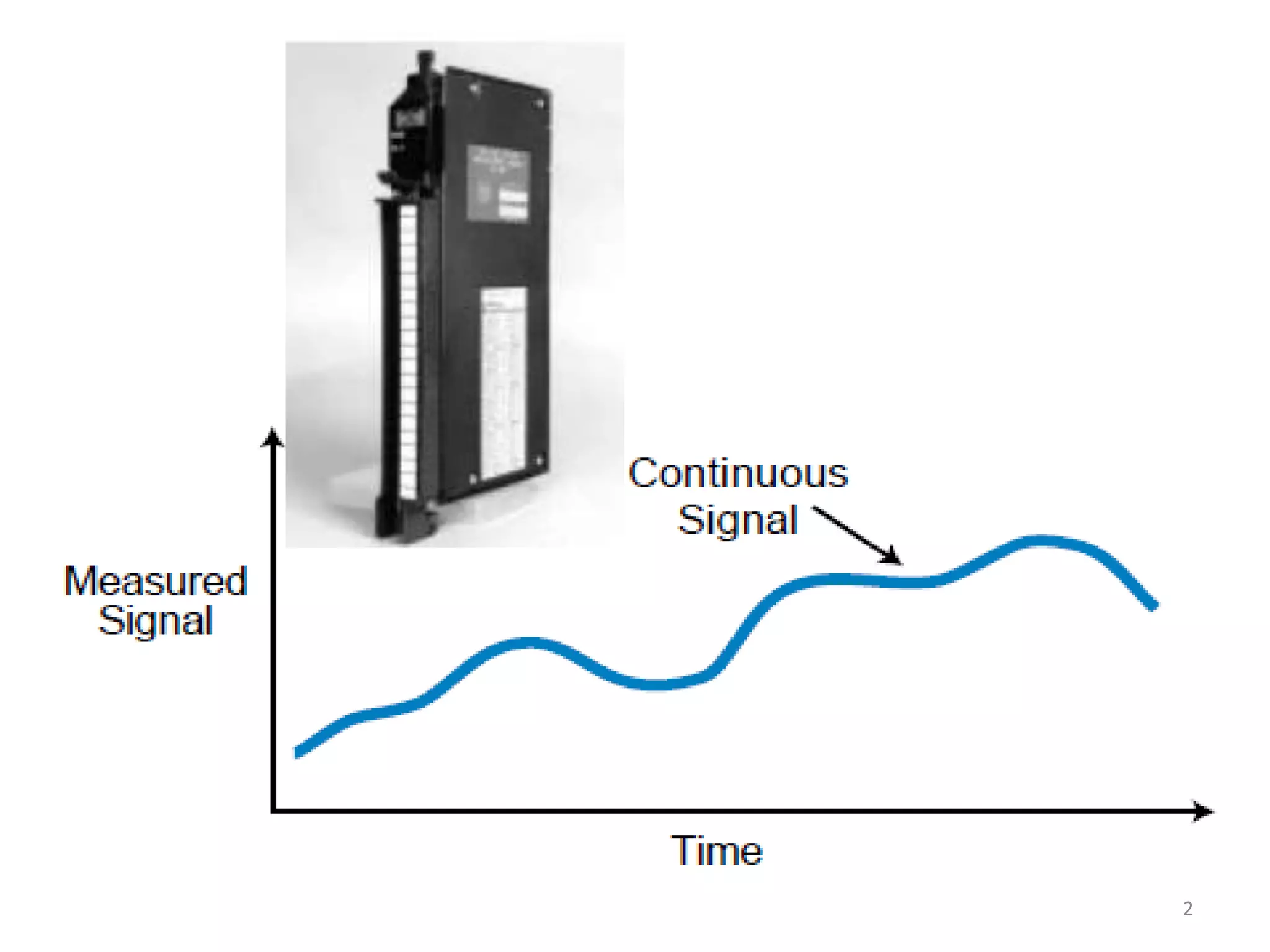
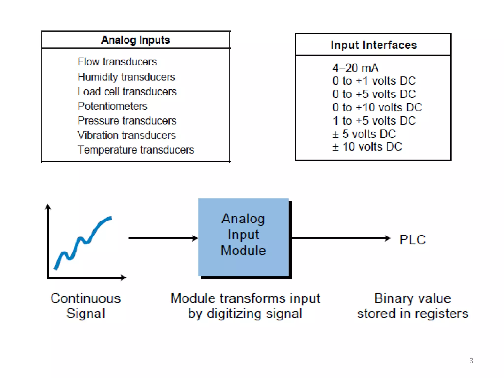
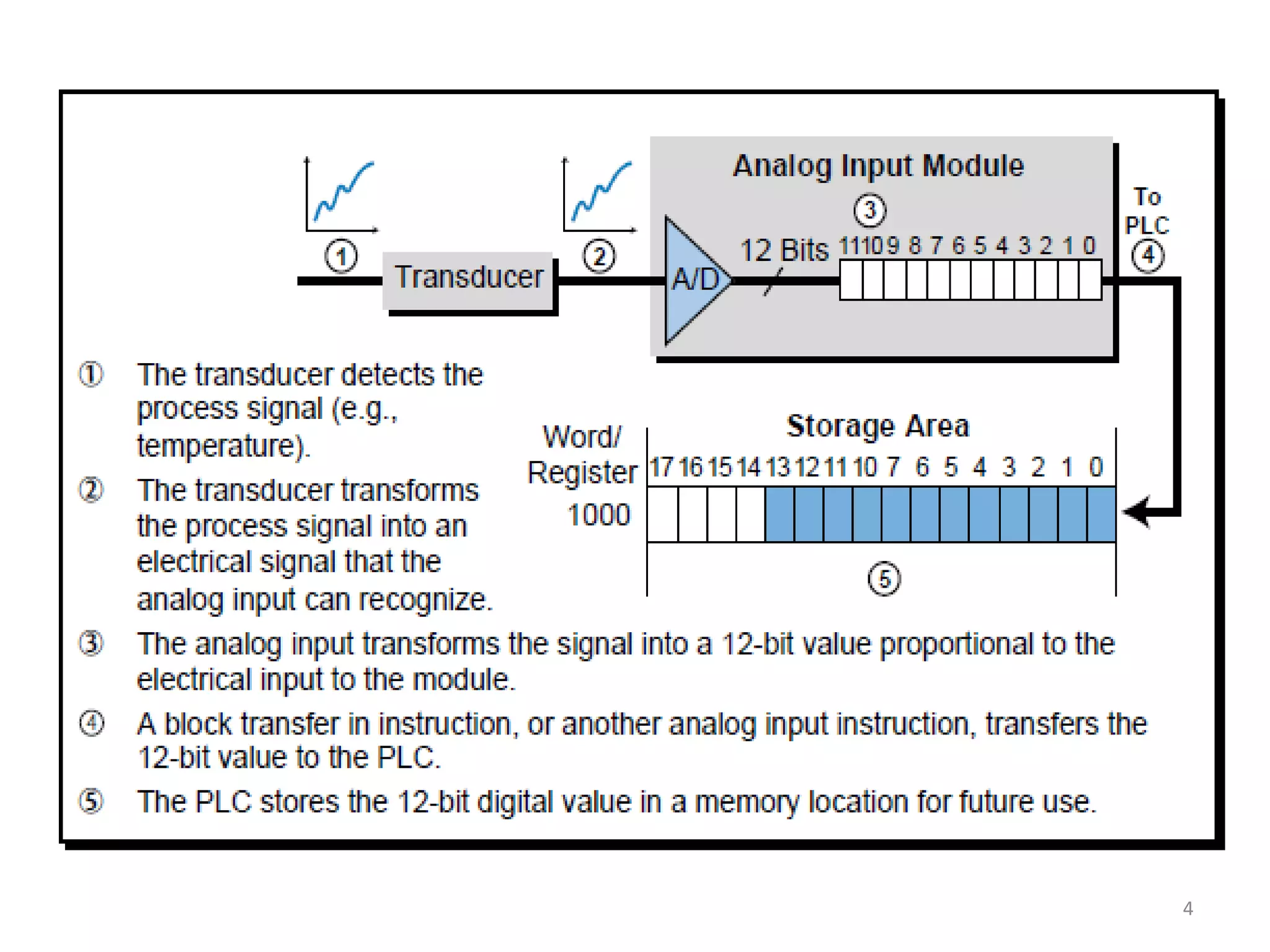
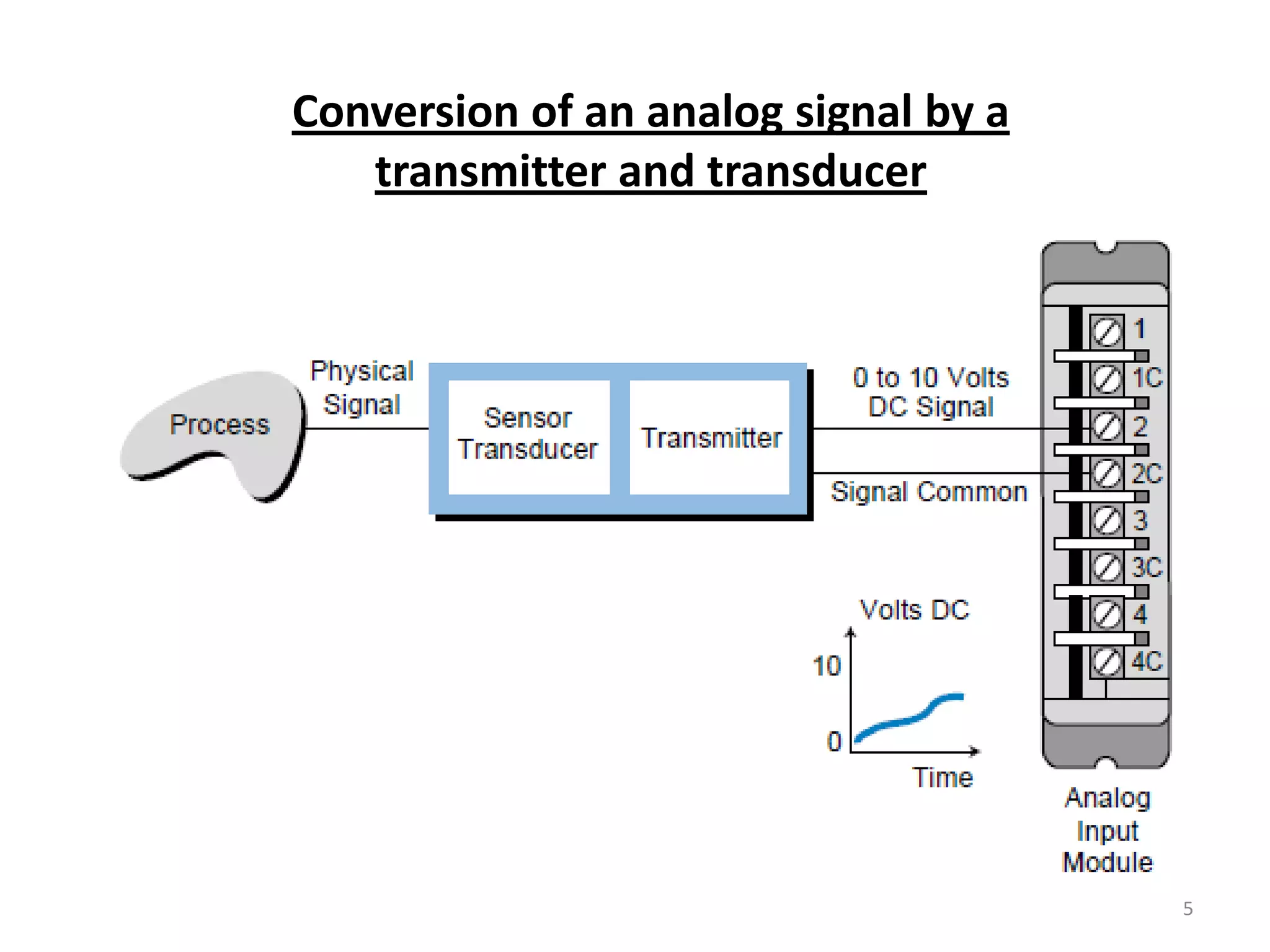
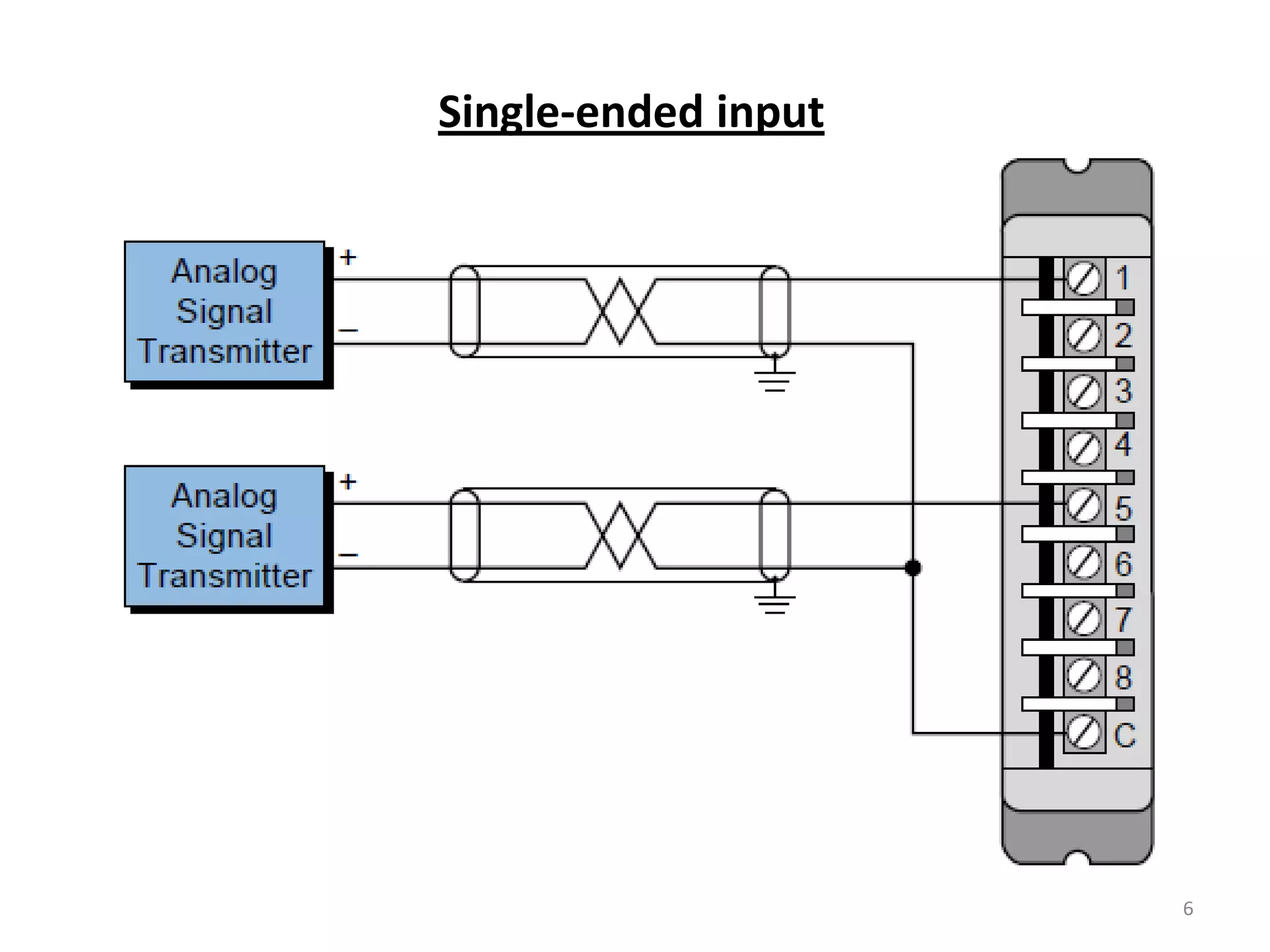
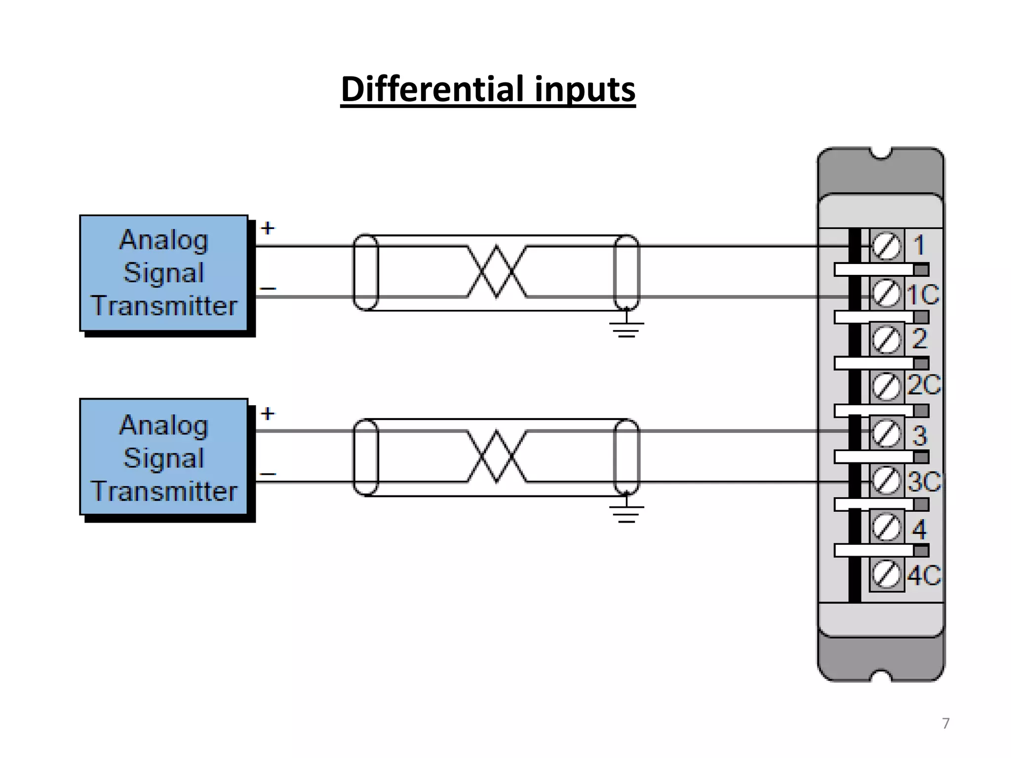
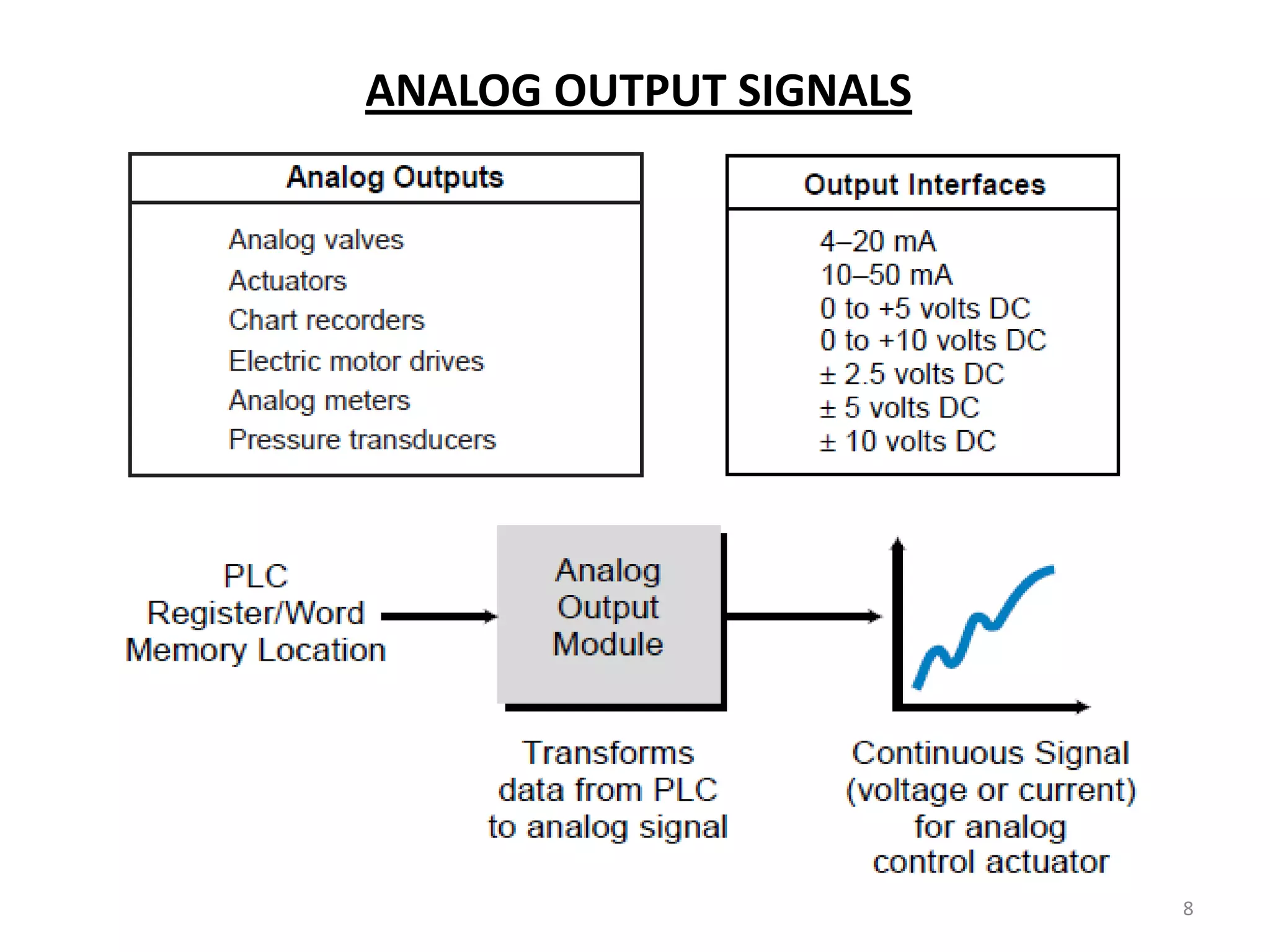
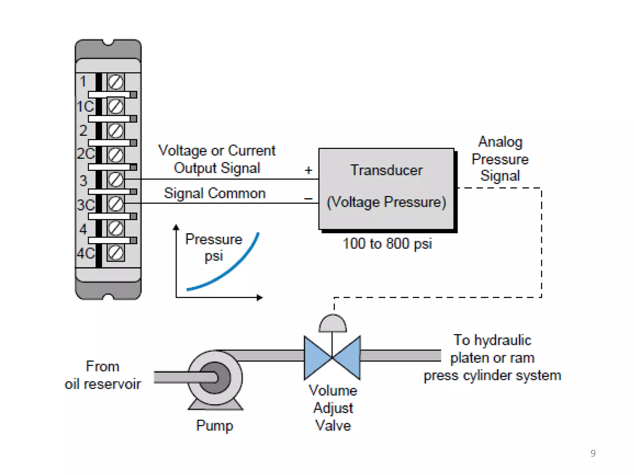
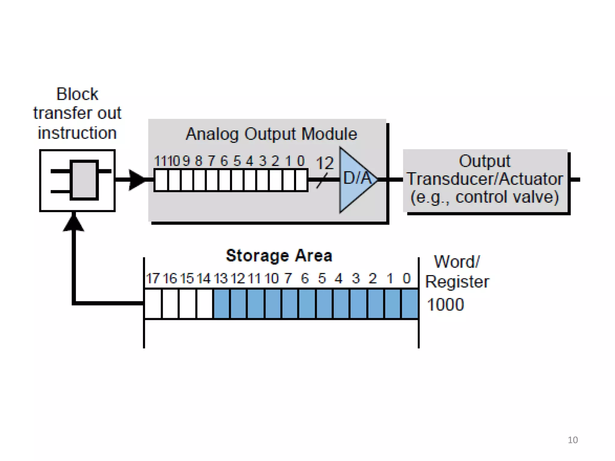
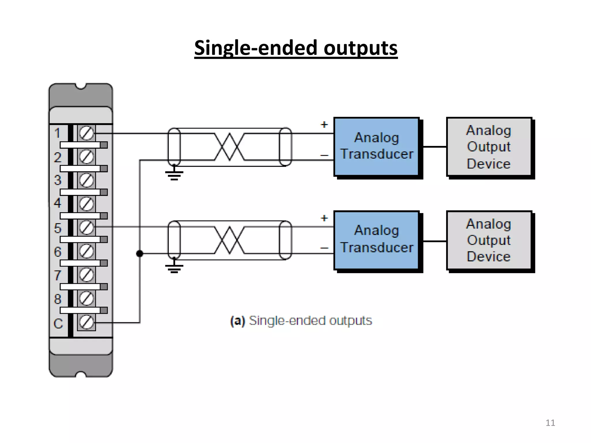
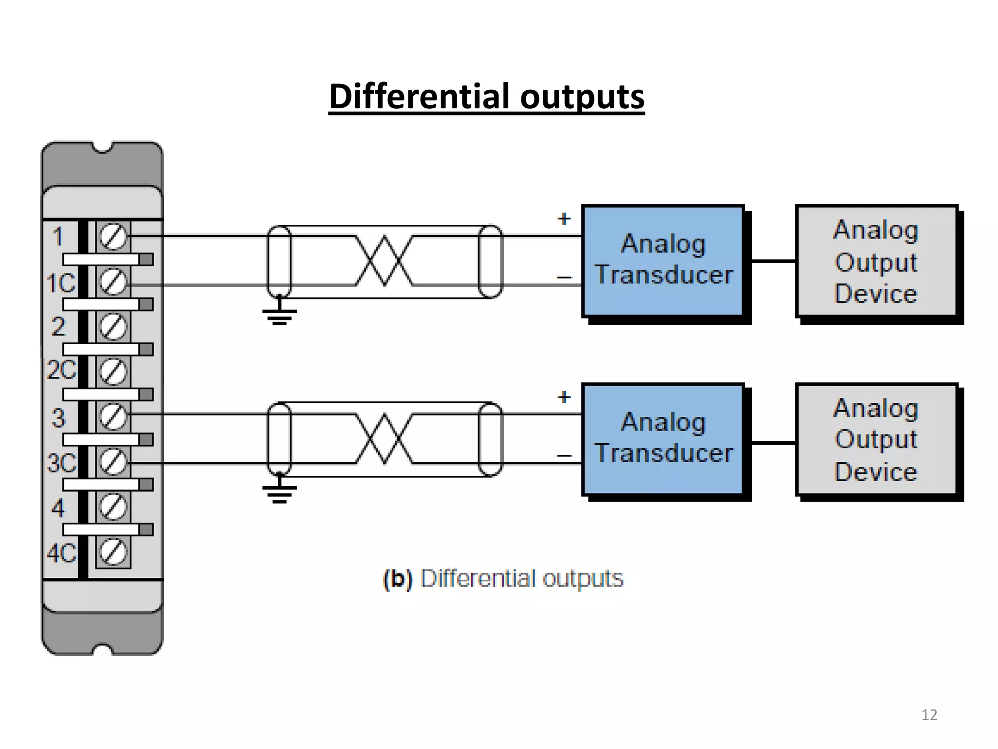
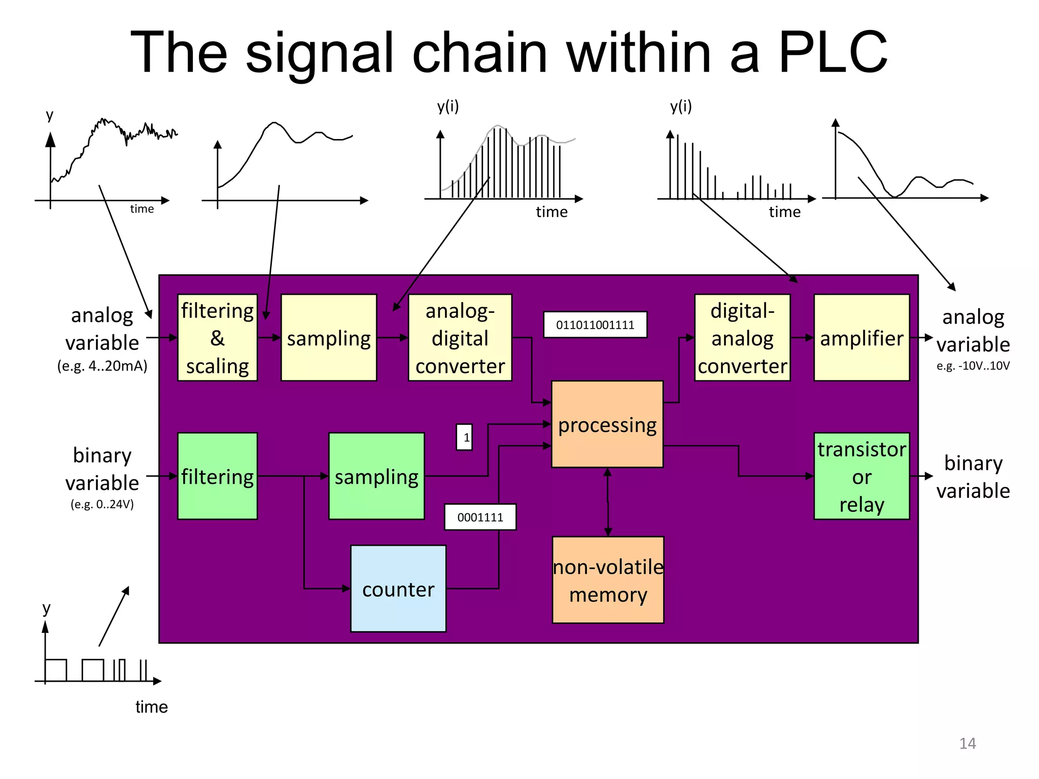
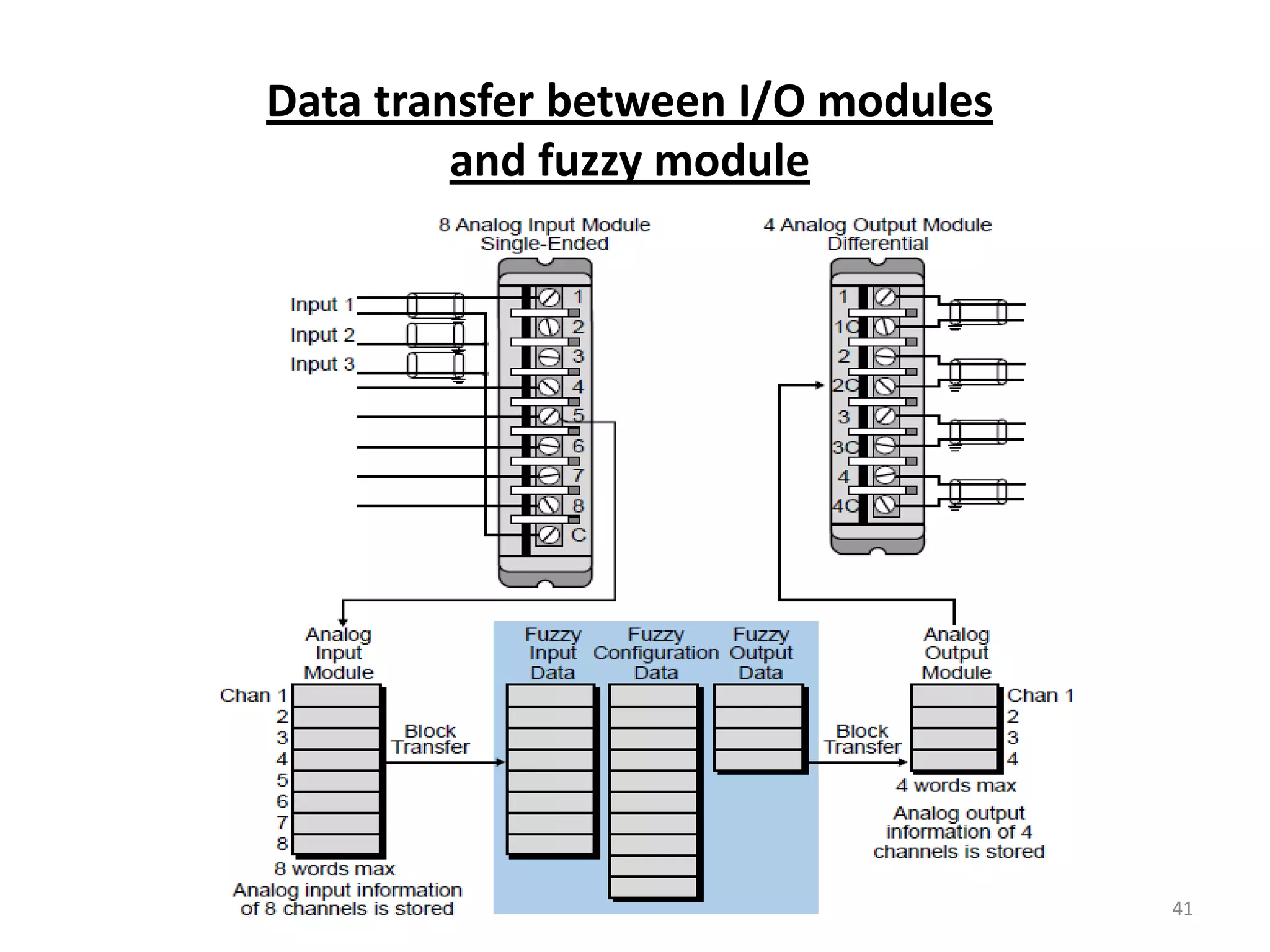
Discusses conversion of analog signals, including single-ended and differential inputs and outputs.
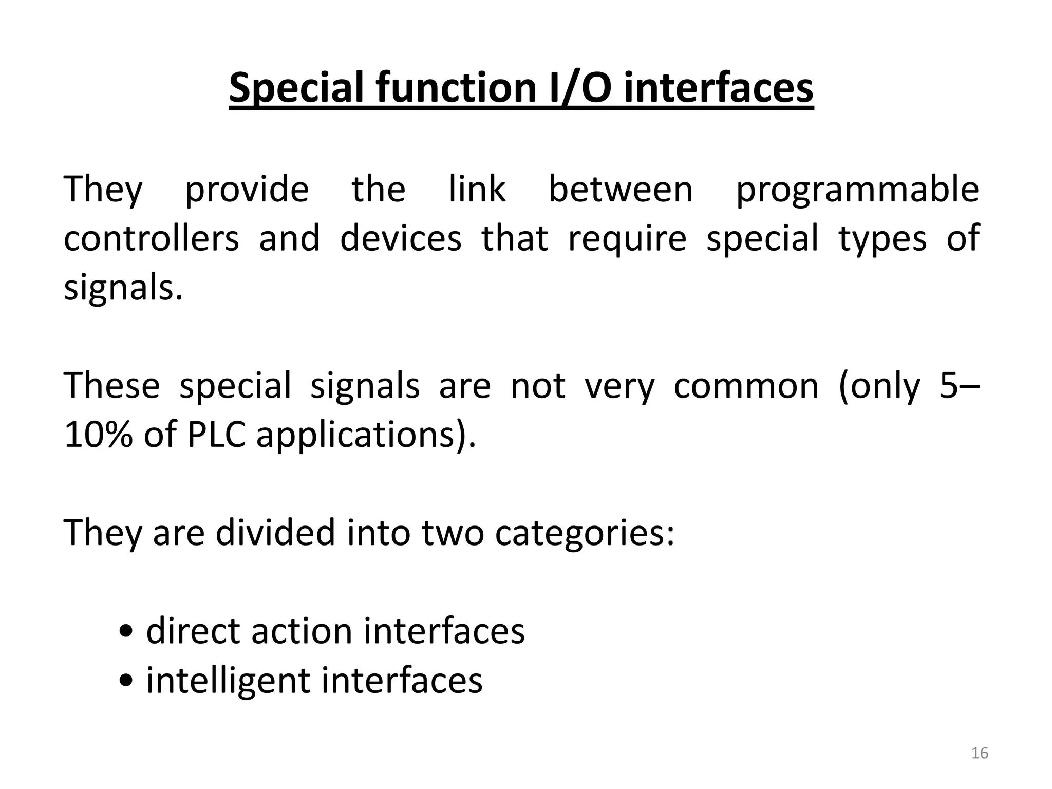
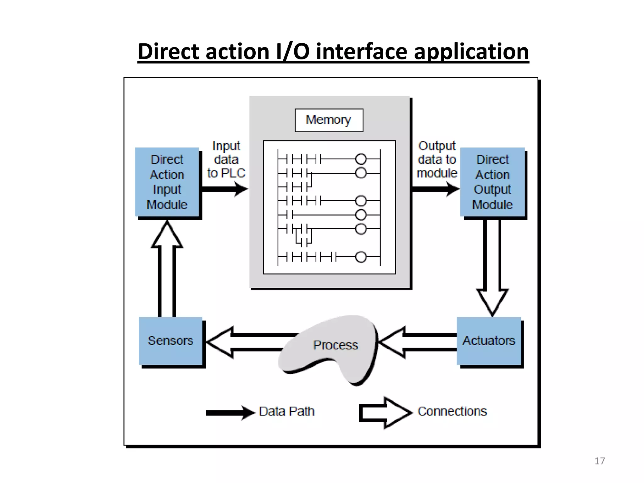
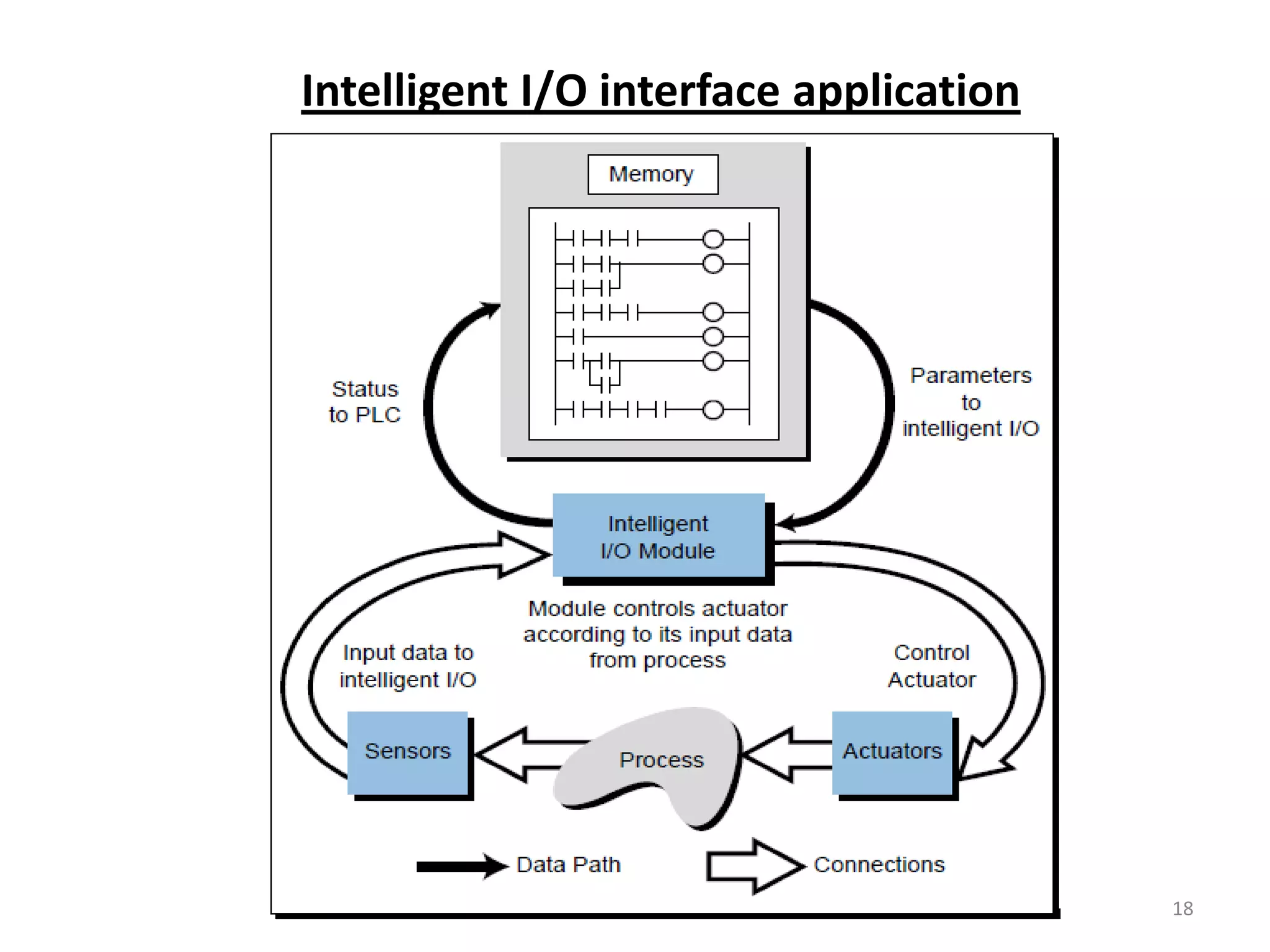
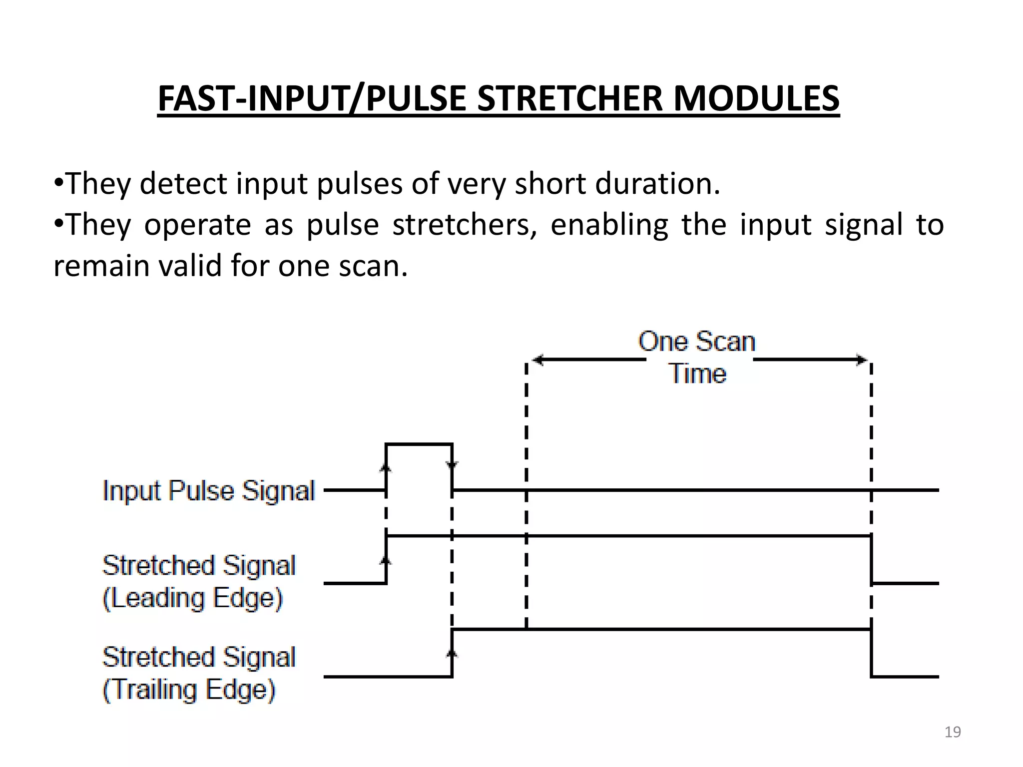
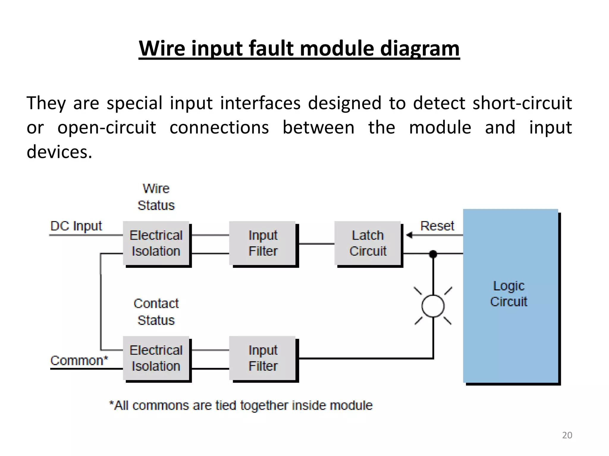
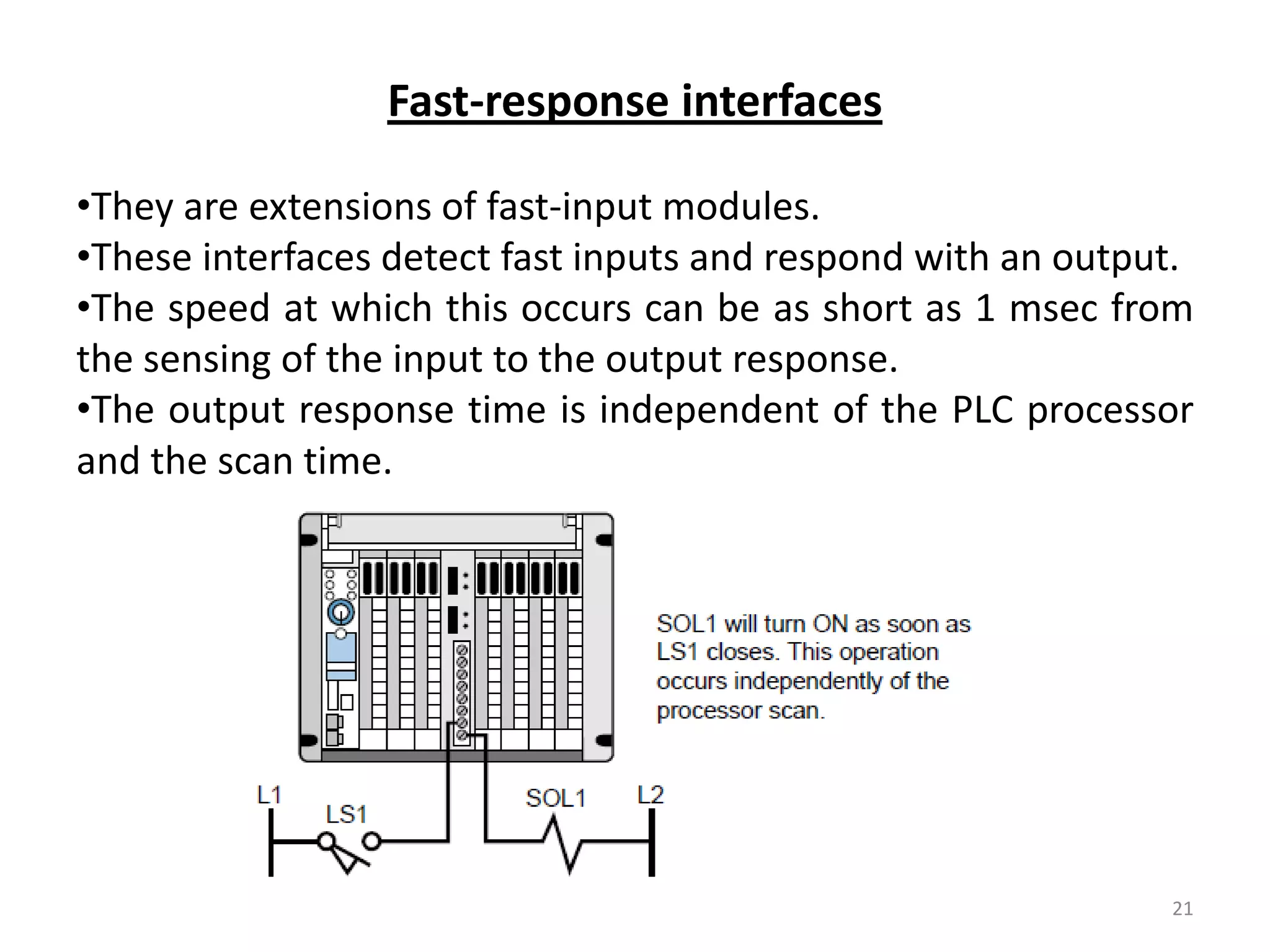
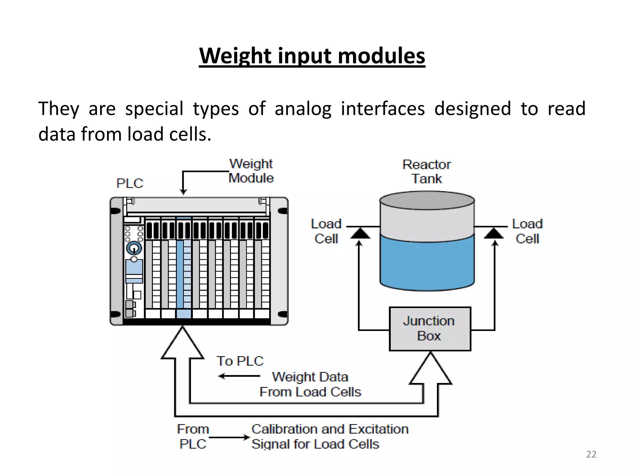
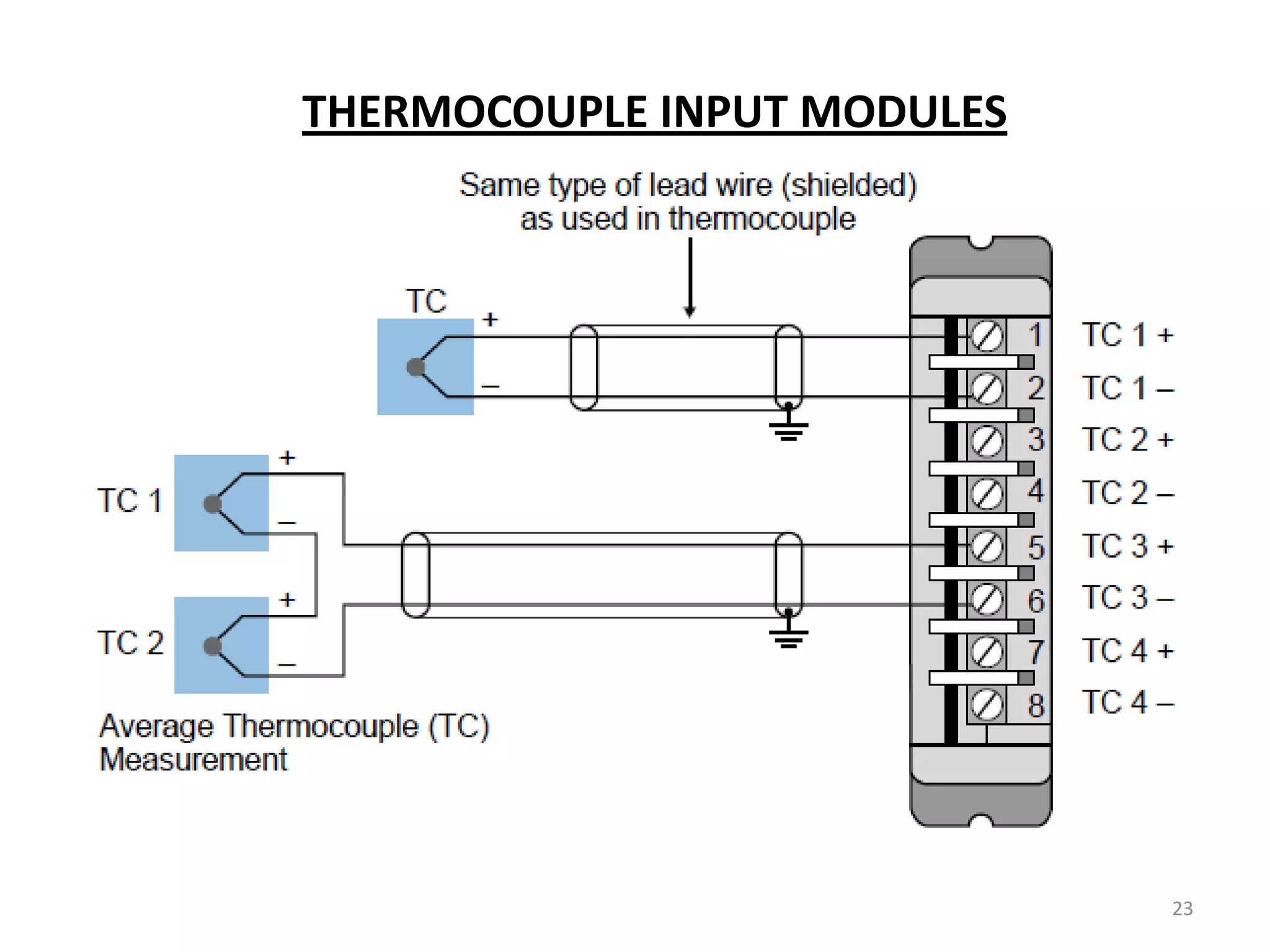
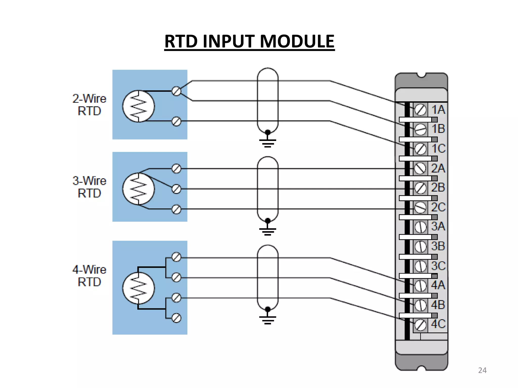
Explains special function I/O interfaces with categories, including direct, intelligent I/O, and modules for specific signal types.
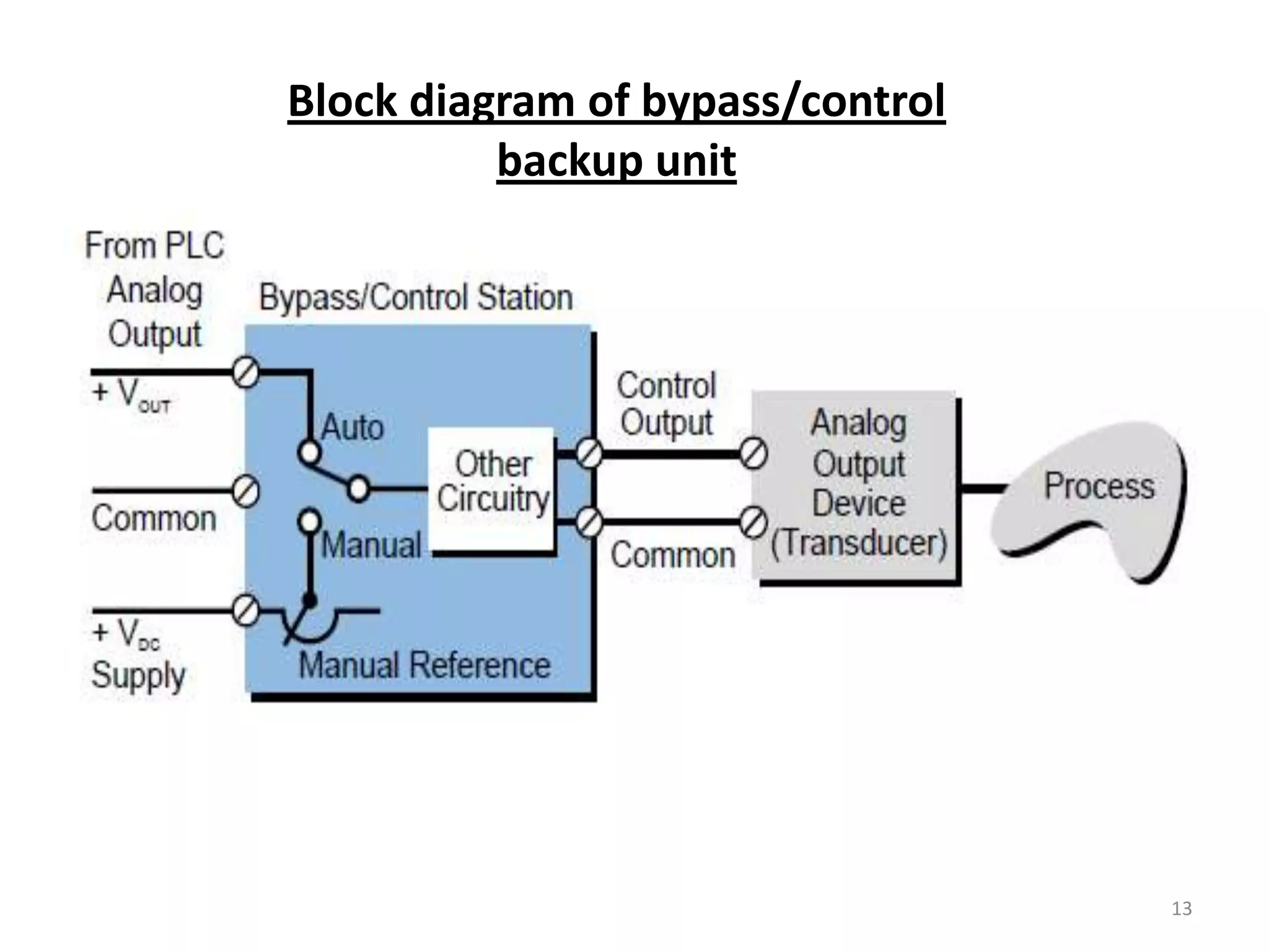
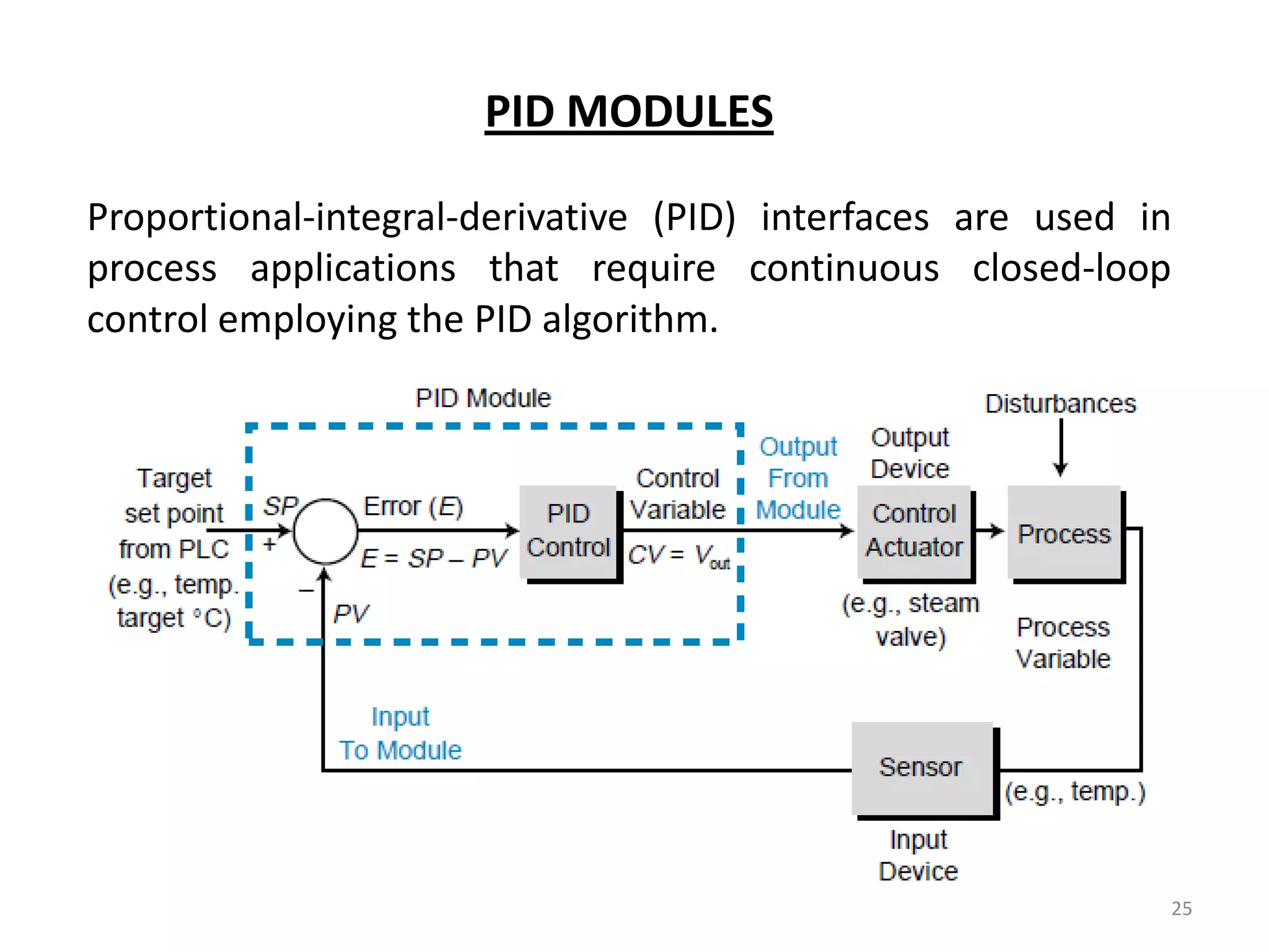
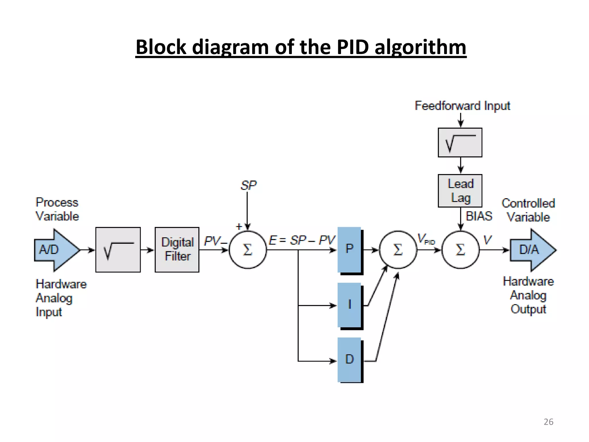
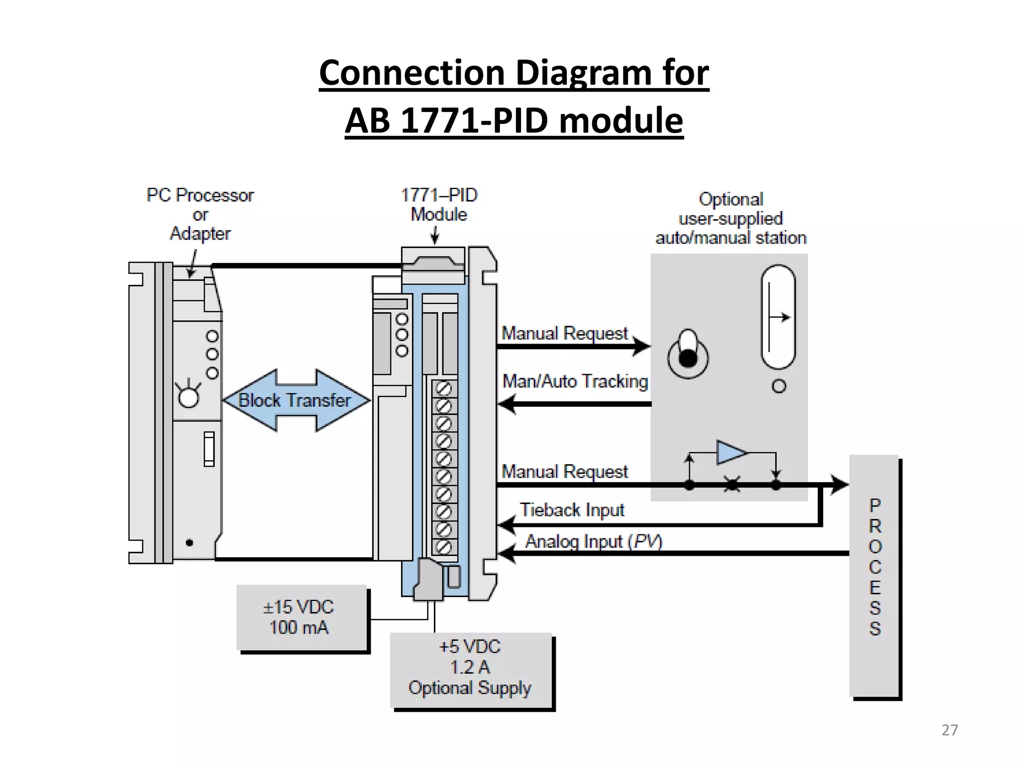
Covers PID modules and algorithms for process control, along with connection diagrams.
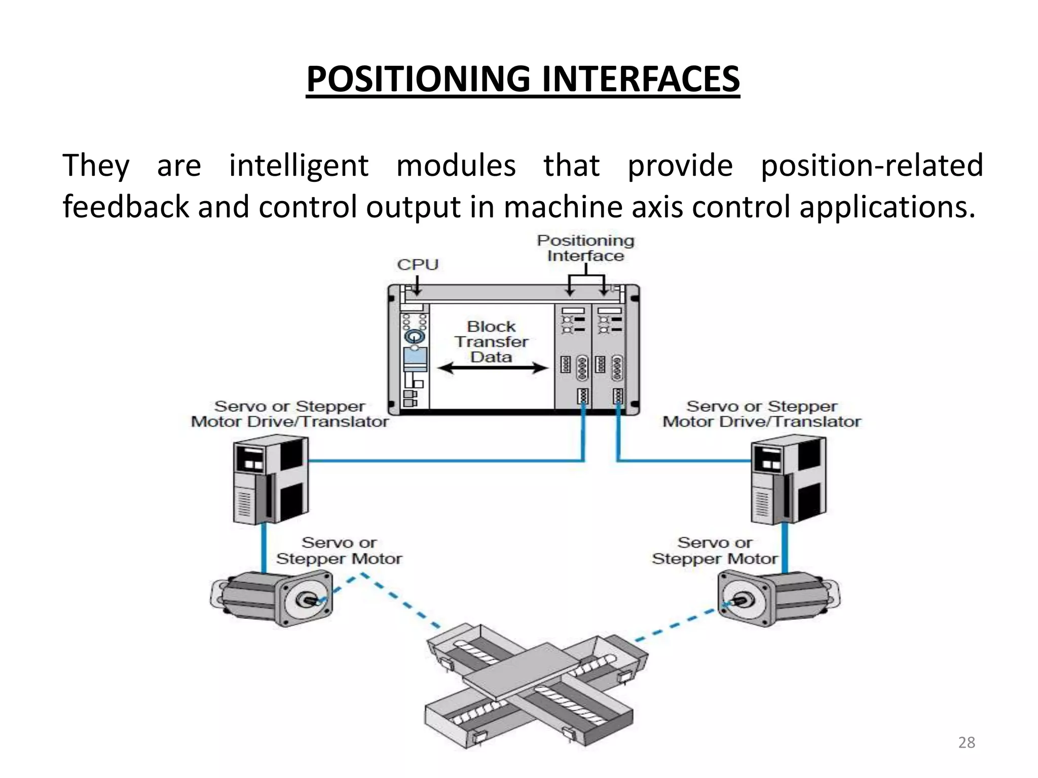
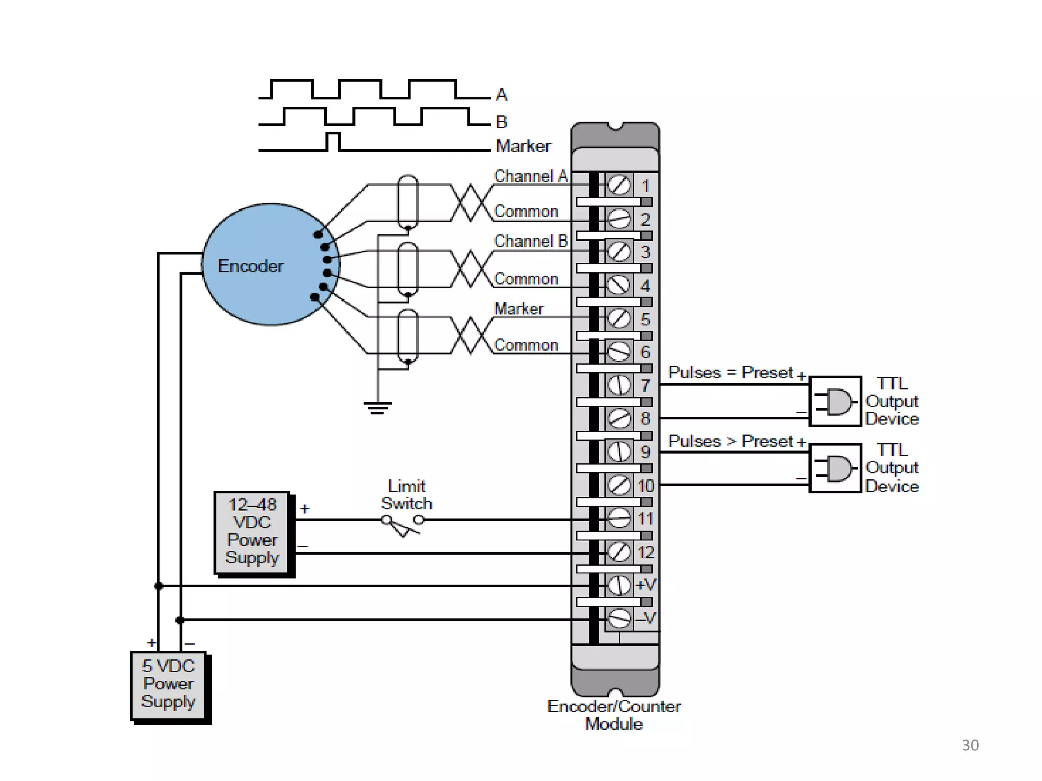
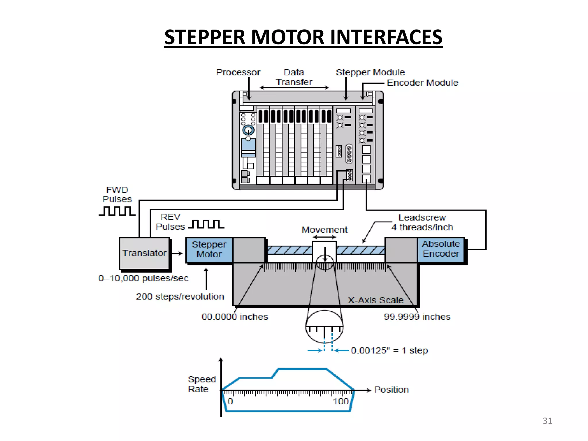
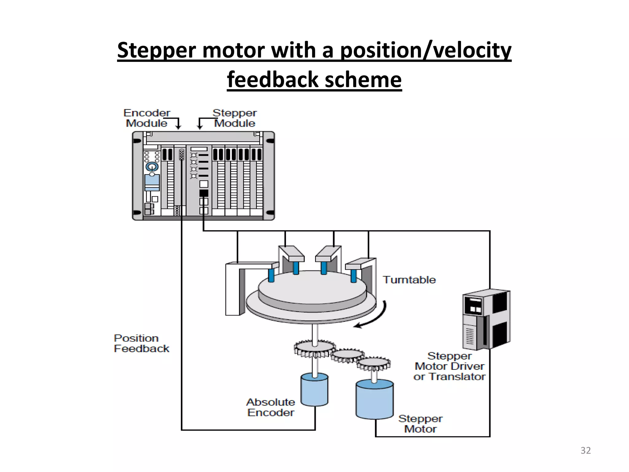
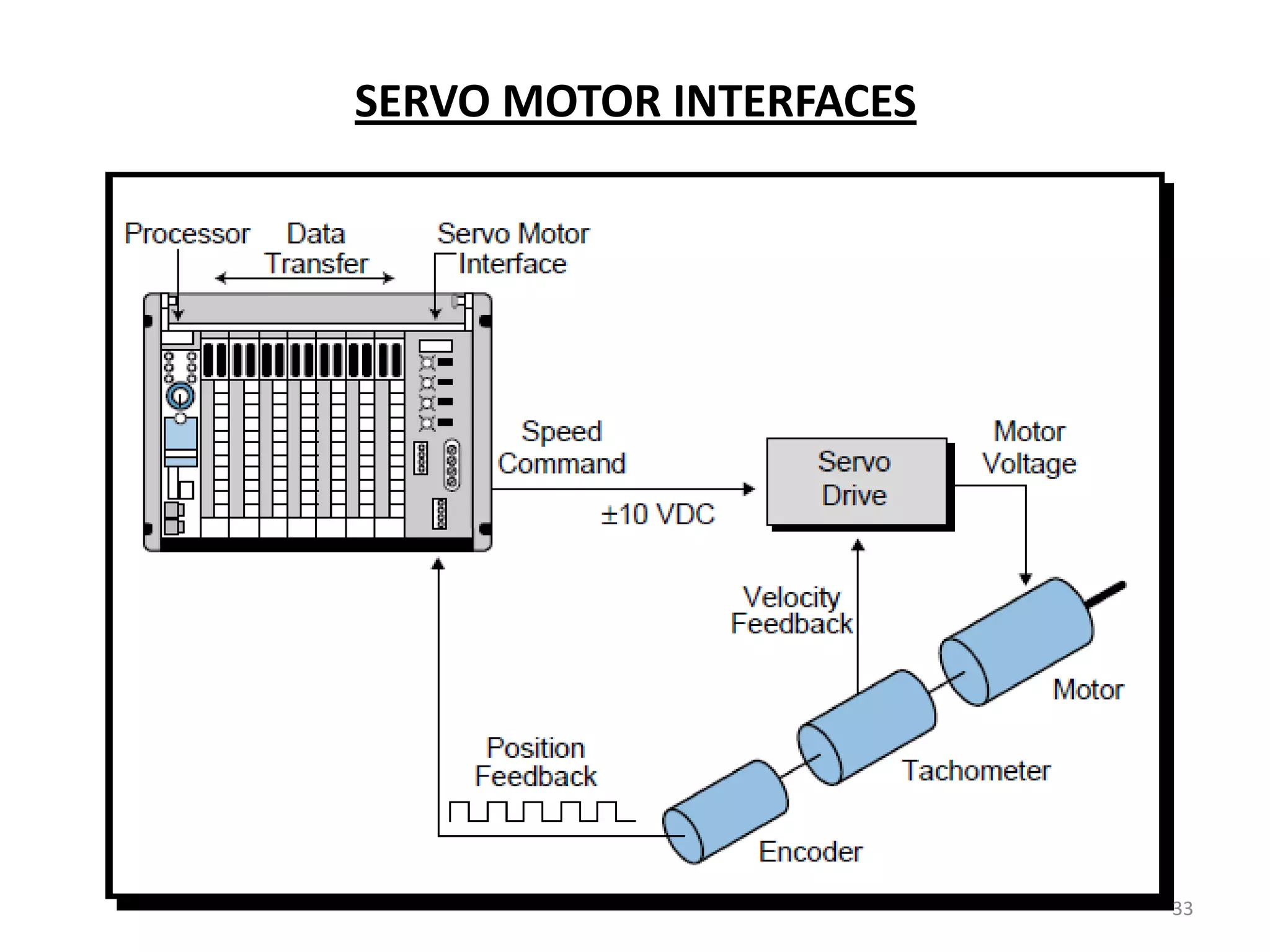
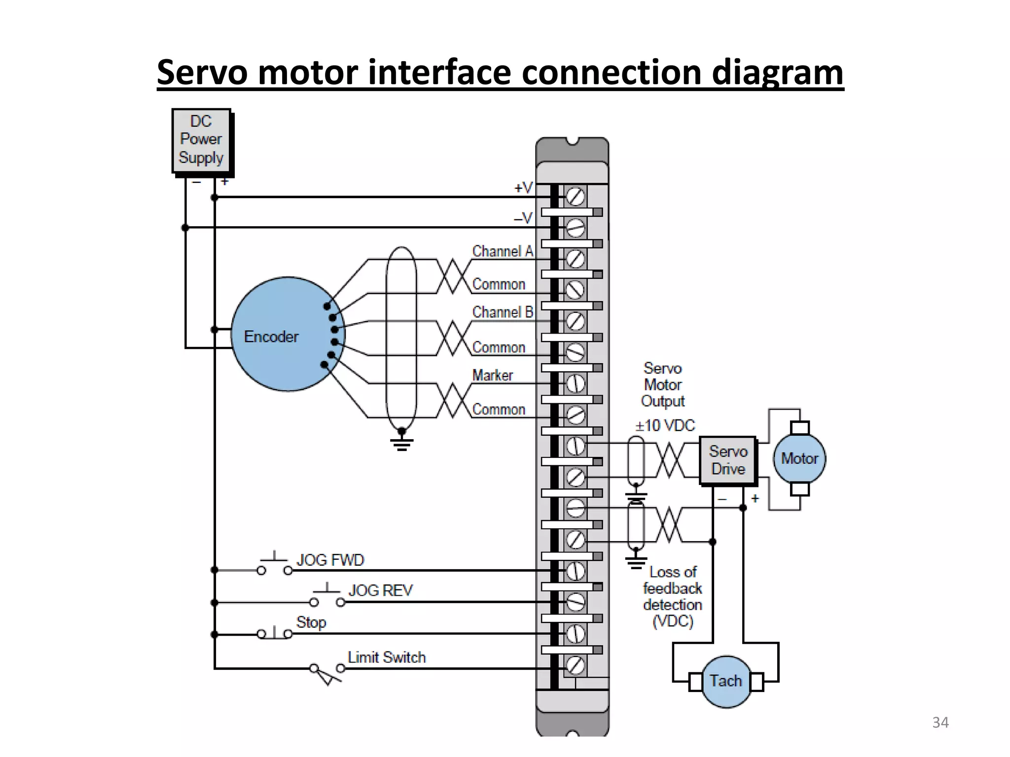
Describes intelligent modules for positioning control and motor interfaces, including stepper and servo motors.
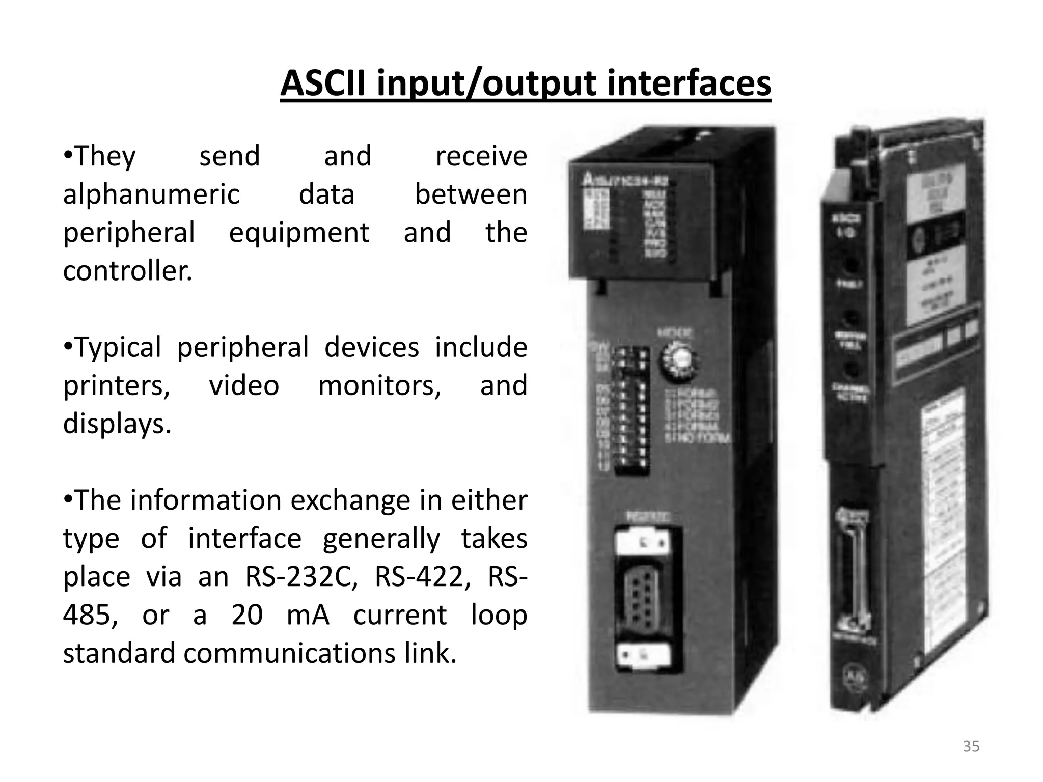
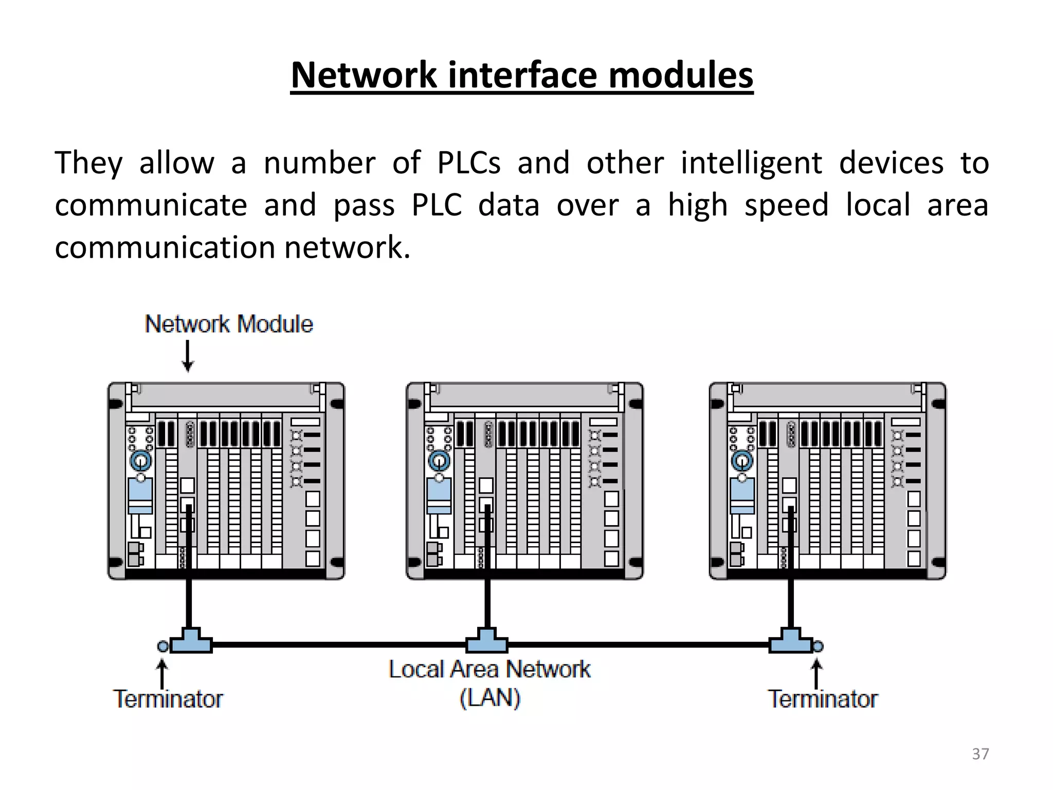
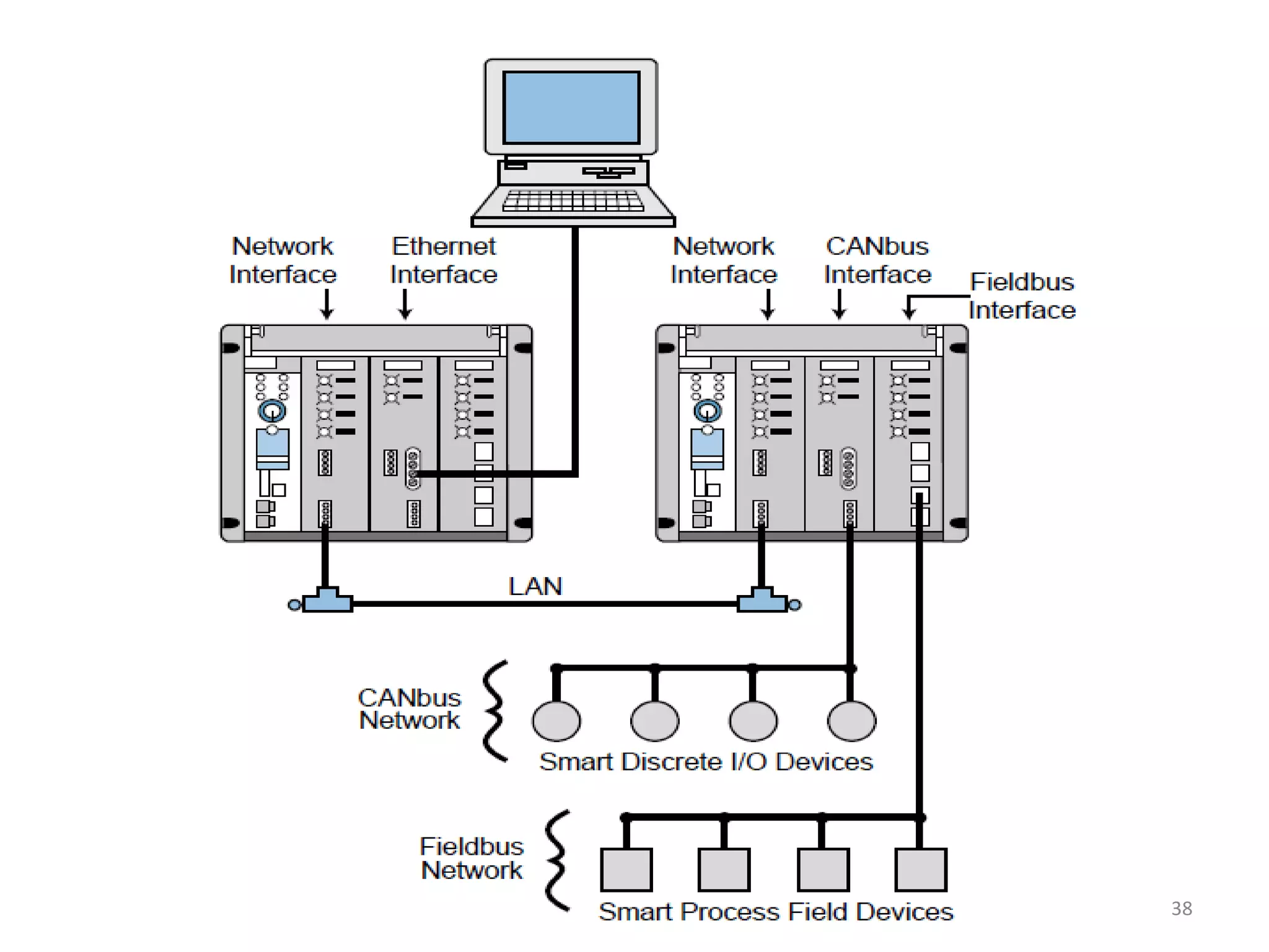
Details on ASCII, computer modules, and network interfaces for PLC communication and data processing.
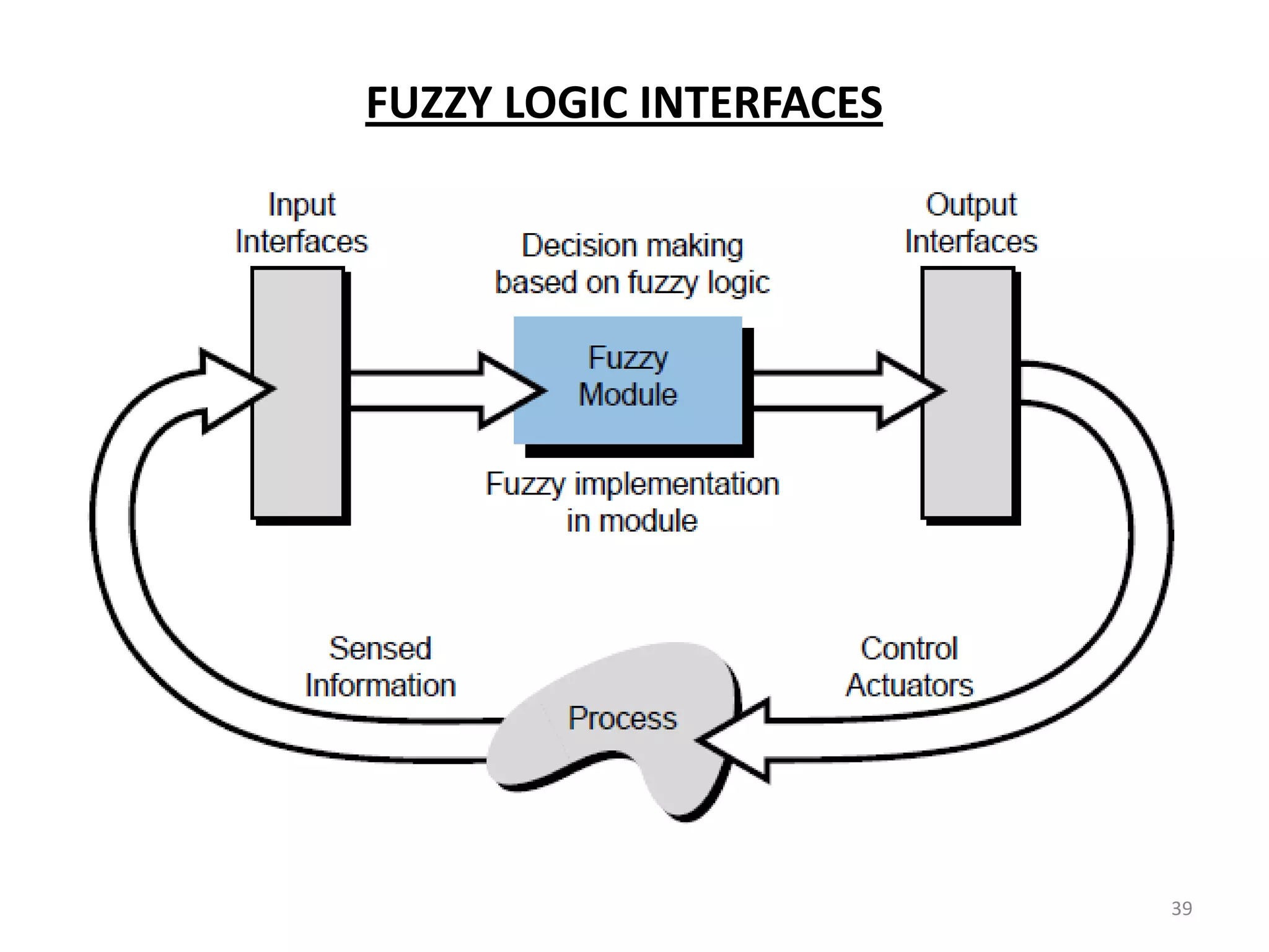
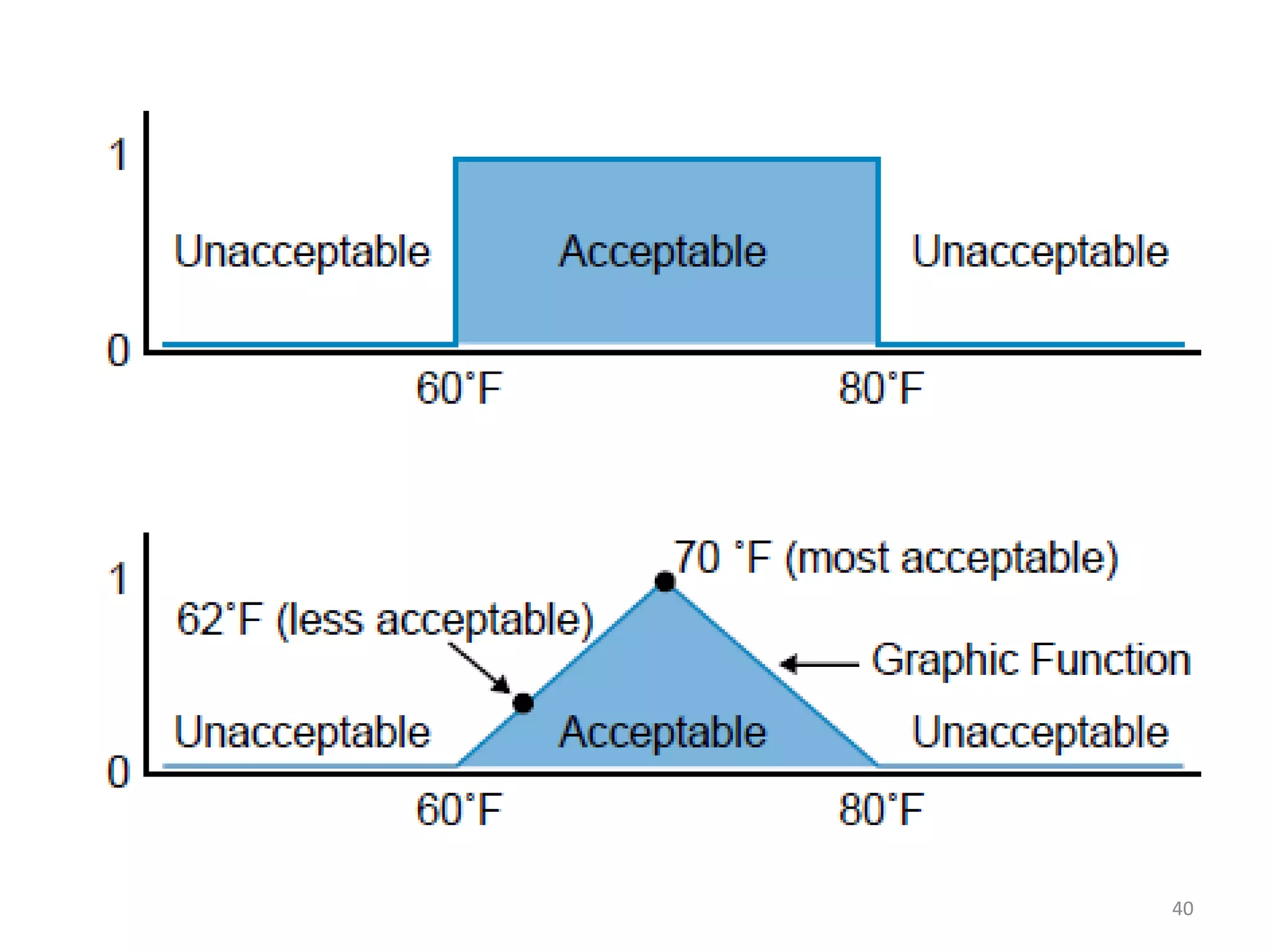
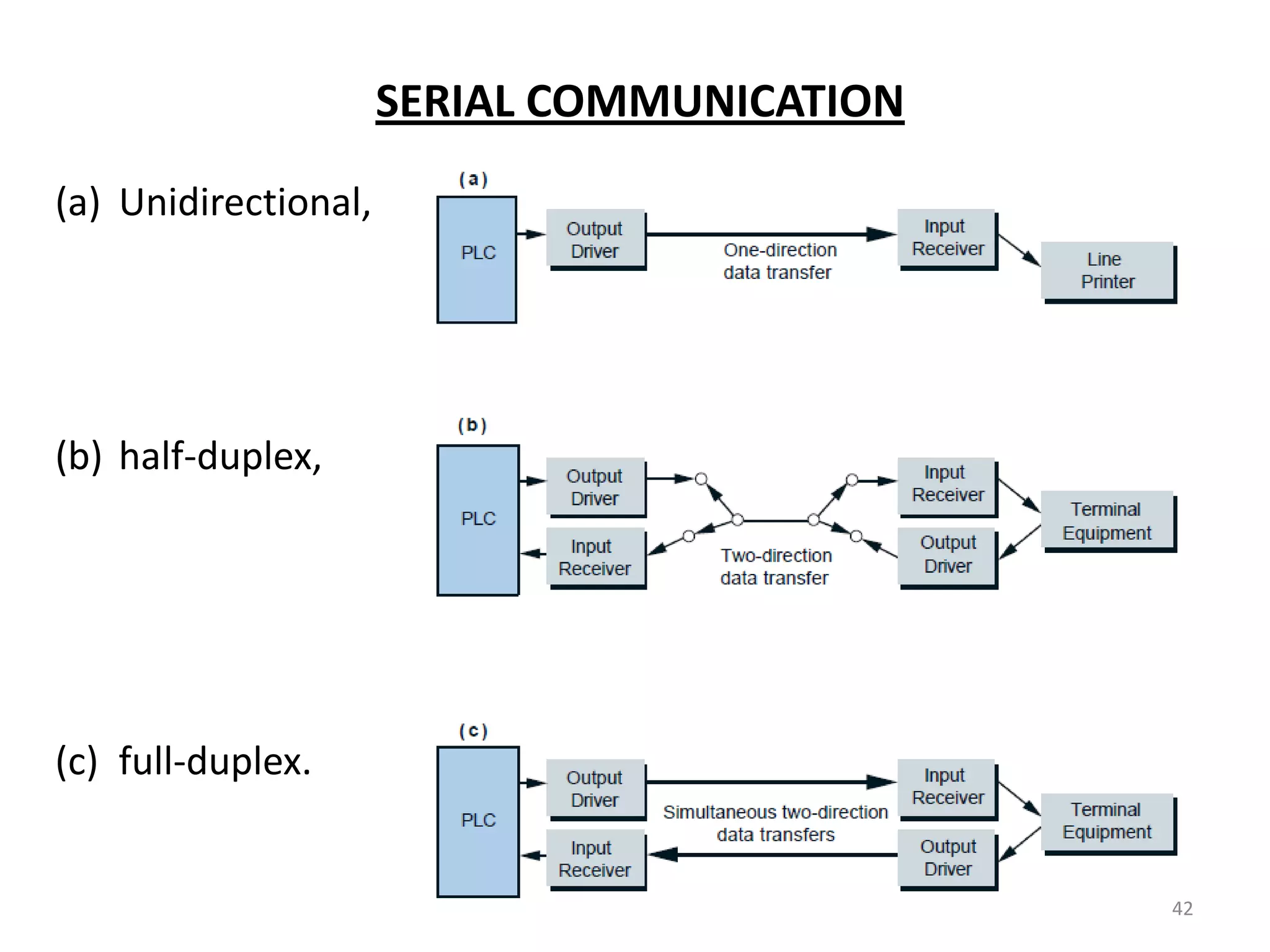
Introduces fuzzy logic interfaces and the types of serial communication protocols.