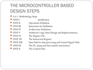
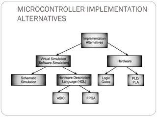
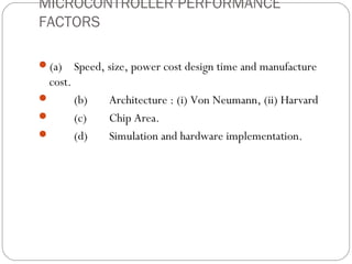
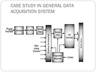
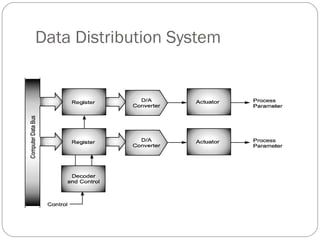
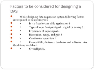
SlideShare a Scribd company logo
1 of 23
CHAPTER 6
 SYSTEM DESIGN
Microcontroller and applications
          ILLUSTRATED BY


     Varsha Patil
THE MICROCONTROLLER BASED
DESIGN STEPS
 6.4.1 Methodology Steps
 STEP I                  Justification
 STEP II       Operations Definition
 STEP III      Instruction Set Definition
 STEP IV       Architecture Definition
 STEP V        Arithmetic Logic Unit (Design and Implementation)
 STEP VI       The Register File
 STEP VII      The Instruction Register
 STEP VIII     Data Path for data processing and Control Signal Table
 STEP IX       The PC, Jump and data transfer instructions
 STEP X        The Control Unit
MICROCONTROLLER IMPLEMENTATION
ALTERNATIVES
Increased productivity yields shorter development cycles
 with more product features and reduced time to market,
Reduced Non-Recurring Engineering (NRE) costs,
Design reuse is enabled,
Increased flexibility to design changes,
MICROCONTROLLER PERFORMANCE
FACTORS

(a)     Speed, size, power cost design time and manufacture
 cost.
        (b)    Architecture : (i) Von Neumann, (ii) Harvard
        (c)    Chip Area.
        (d)    Simulation and hardware implementation.
CASE STUDY IN GENERAL DATA
ACQUISITION SYSTEM
Data Distribution System
Factors to be considered for designing a
DAS
       While designing data acquisition system following factors
  are required to be considered :
       •        Is it a fixed or a mobile application ?
       •        Type of input/output signal : digital or analog ?
       •        Frequency of input signal ?
       •        Resolution, range, and gain ?
       •        Continuous operation ?
       •        Compatibility between hardware and software. Are
  the drivers available ?
       •        Overall price.
Algorithm, Total Number of Lines required :
   (A)         Algorithm :
               1.                Start.
               2.                Select the channel.
               3.                A Low – High transition on ALE to latch in the address.
               4.                A Low – High transition on Start to reset the ADC’s SAR.
               5.                A High – Low transition on ALE.
               6.                A High – Low transition on start to start the conversion.
               7.                Wait for End of cycle (EOC) pin to become high.
               8.                Make Output Enable pin High.
               9.                Take Data from the ADC’s output.
               10.               Make Output Enable pin Low.
               11.               Stop.
   (B)         Total Number of Lines required :
               The total numbers of lines required are total 12 lines, which contain some of the lines like :
               •                 Data lines : 8 numbers.
               •                 ALE line : 1 number.
               •                 START line : 1 number
               •                 EOC line : 1 number
   Output Enable line : 1 number
               •                 We can directly connect the OE pin to Vcc. Moreover instead of polling for EOC just put some delay so
    instead of 12 lines we will require 10 lines.
               •                 We can also provide the clock through the controller thus eliminating the need of external circuit for
    clock.
9 CASE STUDY 2 : ROBOT DEVELOPMENT
Types of Robots
Technologies That Go to Make up a Robot
 3 Classes of Robots
6 Advantages of Robots
7 Disadvantages of Robots
Interfacing Diagram for AT89C2051
 and H-Bridge Driver L293D
(With 5 Volt Power Supply Arrangement)
LM324 Comparator IC Used for Sensing Black Strips

signaling.


                  Inputs                                Function
   Vin H = H          C = H; D = L          Turn Right
   Vin H = H          C = L; D = H          Turn Left
                           C=D              Fast Motor Stop
   Vin H = L          C = X; D = X          Free Running Motor Stop
                   L = Low, H = High, X = Don’t Care

   Use of L293 forms an H-Bridge for bidirectional DC motor driver
: Connection and Timing Diagram for Line
Tracking Sensor
CASE STUDY OF KEYBOARD CONTROLLED ROBOTIC CAR
USING 89C51 MICROCONTROLLER
Case I : Clockwise Direction :
       When A0 = high; A3 = high; & A1 = low; A2 = low.
       The motor rotates in clockwise direction.
 Case II : Anti-Clockwise Direction :
       When A0 = low; A3 = low; & A1 = high; A2 = high.
       The motor rotates in anti-clockwise direction.
 Case III : Motor Stops the Rotation
       When A0 = low; A3 = low; A1 = low; A2 = low
       The motor stops the rotation.
Circuit Diagram of IR Transmitter

 
              Fig. 6.20 : Circuit diagram of IR rtransmitterand Receiver
 What is TCP/IP ?                              (IMP)
           (a)         TCP/IP stands for Transmission Control Protocol/Internet Protocol.
          (b)          TCP/IP is the communication protocol for communication between
    computers on the Internet.
            (c)       A computer communication protocol is a description of the rules computers
    must follow to communicate with each other.
            (d)          TCP/IP defines how electronic devices (like computers) should be connected
    to the Internet, and how data should be transmitted between them.
 The TCP/IP Protocol Architecture(1)                        Main unit (2)           Data
  acquisition module
                 (3)               Data processing module
Data Processing Module and
The Moving Characteristics of the Wheel Control
Interfacing ATmega8535 with CMPS03
(Left) and the Wheel Rotation Counter (Right

More Related Content

What's hot

Microprocessor lab
Microprocessor labMicroprocessor lab
Microprocessor labkpaulraj
 
MIPI DevCon 2016: MIPI C-PHY - Introduction From Basic Theory to Practical Im...
MIPI DevCon 2016: MIPI C-PHY - Introduction From Basic Theory to Practical Im...MIPI DevCon 2016: MIPI C-PHY - Introduction From Basic Theory to Practical Im...
MIPI DevCon 2016: MIPI C-PHY - Introduction From Basic Theory to Practical Im...MIPI Alliance
 
A high speed dynamic ripple carry adder
A high speed dynamic ripple carry adderA high speed dynamic ripple carry adder
A high speed dynamic ripple carry addereSAT Journals
 
Microprocessor and Microcontroller Lab Manual!
Microprocessor and Microcontroller Lab Manual!Microprocessor and Microcontroller Lab Manual!
Microprocessor and Microcontroller Lab Manual!PRABHAHARAN429
 
Unit iv microcontrollers final
Unit iv microcontrollers finalUnit iv microcontrollers final
Unit iv microcontrollers finalSARITHA REDDY
 
Study on self resetting logic with gate diffusion input (SRL-GDI)
Study on self resetting logic with gate diffusion input (SRL-GDI)Study on self resetting logic with gate diffusion input (SRL-GDI)
Study on self resetting logic with gate diffusion input (SRL-GDI)shubham jha
 
8085 Paper Presentation slides,ppt,microprocessor 8085 ,guide, instruction set
8085 Paper Presentation slides,ppt,microprocessor 8085 ,guide, instruction set8085 Paper Presentation slides,ppt,microprocessor 8085 ,guide, instruction set
8085 Paper Presentation slides,ppt,microprocessor 8085 ,guide, instruction setSaumitra Rukmangad
 
Ec2308 microprocessor and_microcontroller__lab1
Ec2308 microprocessor and_microcontroller__lab1Ec2308 microprocessor and_microcontroller__lab1
Ec2308 microprocessor and_microcontroller__lab1v1i7n9i2
 
SAP II ARTICTURE ,SAP 2
SAP II ARTICTURE ,SAP 2SAP II ARTICTURE ,SAP 2
SAP II ARTICTURE ,SAP 2Apar Pramod
 
8051 basic programming
8051 basic programming8051 basic programming
8051 basic programmingANJUSHA R
 

What's hot (20)

Acc logic
Acc logicAcc logic
Acc logic
 
Microprocessor lab
Microprocessor labMicroprocessor lab
Microprocessor lab
 
Abc2
Abc2Abc2
Abc2
 
MIPI DevCon 2016: MIPI C-PHY - Introduction From Basic Theory to Practical Im...
MIPI DevCon 2016: MIPI C-PHY - Introduction From Basic Theory to Practical Im...MIPI DevCon 2016: MIPI C-PHY - Introduction From Basic Theory to Practical Im...
MIPI DevCon 2016: MIPI C-PHY - Introduction From Basic Theory to Practical Im...
 
Microprocessor File
Microprocessor FileMicroprocessor File
Microprocessor File
 
A high speed dynamic ripple carry adder
A high speed dynamic ripple carry adderA high speed dynamic ripple carry adder
A high speed dynamic ripple carry adder
 
Microprocessor and Microcontroller Lab Manual!
Microprocessor and Microcontroller Lab Manual!Microprocessor and Microcontroller Lab Manual!
Microprocessor and Microcontroller Lab Manual!
 
Unit iv microcontrollers final
Unit iv microcontrollers finalUnit iv microcontrollers final
Unit iv microcontrollers final
 
Traffic signal design study
Traffic signal design studyTraffic signal design study
Traffic signal design study
 
Study on self resetting logic with gate diffusion input (SRL-GDI)
Study on self resetting logic with gate diffusion input (SRL-GDI)Study on self resetting logic with gate diffusion input (SRL-GDI)
Study on self resetting logic with gate diffusion input (SRL-GDI)
 
Class10
Class10Class10
Class10
 
11 hr1a0401
11 hr1a040111 hr1a0401
11 hr1a0401
 
8085 Paper Presentation slides,ppt,microprocessor 8085 ,guide, instruction set
8085 Paper Presentation slides,ppt,microprocessor 8085 ,guide, instruction set8085 Paper Presentation slides,ppt,microprocessor 8085 ,guide, instruction set
8085 Paper Presentation slides,ppt,microprocessor 8085 ,guide, instruction set
 
Lec03
Lec03Lec03
Lec03
 
OPAL-RT RT14: MMC in RT-LAB
OPAL-RT RT14: MMC in RT-LABOPAL-RT RT14: MMC in RT-LAB
OPAL-RT RT14: MMC in RT-LAB
 
Ec2308 microprocessor and_microcontroller__lab1
Ec2308 microprocessor and_microcontroller__lab1Ec2308 microprocessor and_microcontroller__lab1
Ec2308 microprocessor and_microcontroller__lab1
 
SAP II ARTICTURE ,SAP 2
SAP II ARTICTURE ,SAP 2SAP II ARTICTURE ,SAP 2
SAP II ARTICTURE ,SAP 2
 
8085 instructions
8085 instructions8085 instructions
8085 instructions
 
Lec14
Lec14Lec14
Lec14
 
8051 basic programming
8051 basic programming8051 basic programming
8051 basic programming
 

Similar to Varsha patil AISSMS IOIT Pune mca te pu book

analog to digital converter and dac final
analog to digital converter and dac finalanalog to digital converter and dac final
analog to digital converter and dac finalDrVikasMahor
 
ADC and DAC interfacing.pdf
ADC and DAC interfacing.pdfADC and DAC interfacing.pdf
ADC and DAC interfacing.pdfVikasMahor3
 
Unit iii microcontrollers final1
Unit iii microcontrollers final1Unit iii microcontrollers final1
Unit iii microcontrollers final1Saritha Reddy
 
MPC of TWT based Transmitter
MPC of TWT based TransmitterMPC of TWT based Transmitter
MPC of TWT based TransmitterAbhishek Sutrave
 
IEEE Paper A SystemC AMS Model of an I2C Bus Controller
IEEE Paper A SystemC AMS Model  of an I2C Bus ControllerIEEE Paper A SystemC AMS Model  of an I2C Bus Controller
IEEE Paper A SystemC AMS Model of an I2C Bus ControllerDweapons Art
 
Interfacing with peripherals: analog to digital converters and digital to ana...
Interfacing with peripherals: analog to digital converters and digital to ana...Interfacing with peripherals: analog to digital converters and digital to ana...
Interfacing with peripherals: analog to digital converters and digital to ana...NimeshSingh27
 
combinational logic circuit and sequential logic circuit.pptx
combinational logic circuit and sequential logic circuit.pptxcombinational logic circuit and sequential logic circuit.pptx
combinational logic circuit and sequential logic circuit.pptxAhmedLakhwera
 
Industrial training report of embedded system and robotics
Industrial training report of embedded system and roboticsIndustrial training report of embedded system and robotics
Industrial training report of embedded system and roboticsPallavi Bharti
 
Analog to Digital Converters
Analog to Digital ConvertersAnalog to Digital Converters
Analog to Digital ConvertersAmitabh Shukla
 
Design of Low-Power High-Speed Truncation-Error-Tolerant Adder
Design of Low-Power High-Speed  Truncation-Error-Tolerant Adder Design of Low-Power High-Speed  Truncation-Error-Tolerant Adder
Design of Low-Power High-Speed Truncation-Error-Tolerant Adder Sravankumar Samboju
 
Embedded systems, 8051 microcontroller
Embedded systems, 8051 microcontrollerEmbedded systems, 8051 microcontroller
Embedded systems, 8051 microcontrollerAmandeep Alag
 
8085 microprocessor(1)
8085 microprocessor(1)8085 microprocessor(1)
8085 microprocessor(1)Reevu Pal
 
CLC and SLC with examples.pptx
CLC and SLC with examples.pptxCLC and SLC with examples.pptx
CLC and SLC with examples.pptxAhmedLakhwera
 
underground cable fault location using aruino,gsm&gps
underground cable fault location using aruino,gsm&gps underground cable fault location using aruino,gsm&gps
underground cable fault location using aruino,gsm&gps Mohd Sohail
 

Similar to Varsha patil AISSMS IOIT Pune mca te pu book (20)

analog to digital converter and dac final
analog to digital converter and dac finalanalog to digital converter and dac final
analog to digital converter and dac final
 
ADC and DAC interfacing.pdf
ADC and DAC interfacing.pdfADC and DAC interfacing.pdf
ADC and DAC interfacing.pdf
 
Unit iii microcontrollers final1
Unit iii microcontrollers final1Unit iii microcontrollers final1
Unit iii microcontrollers final1
 
MPC of TWT based Transmitter
MPC of TWT based TransmitterMPC of TWT based Transmitter
MPC of TWT based Transmitter
 
IEEE Paper A SystemC AMS Model of an I2C Bus Controller
IEEE Paper A SystemC AMS Model  of an I2C Bus ControllerIEEE Paper A SystemC AMS Model  of an I2C Bus Controller
IEEE Paper A SystemC AMS Model of an I2C Bus Controller
 
Interfacing with peripherals: analog to digital converters and digital to ana...
Interfacing with peripherals: analog to digital converters and digital to ana...Interfacing with peripherals: analog to digital converters and digital to ana...
Interfacing with peripherals: analog to digital converters and digital to ana...
 
combinational logic circuit and sequential logic circuit.pptx
combinational logic circuit and sequential logic circuit.pptxcombinational logic circuit and sequential logic circuit.pptx
combinational logic circuit and sequential logic circuit.pptx
 
Analog to Digital Converter
Analog to Digital ConverterAnalog to Digital Converter
Analog to Digital Converter
 
Badal sharma
Badal sharmaBadal sharma
Badal sharma
 
project 3 full report
project 3 full reportproject 3 full report
project 3 full report
 
Industrial training report of embedded system and robotics
Industrial training report of embedded system and roboticsIndustrial training report of embedded system and robotics
Industrial training report of embedded system and robotics
 
Analog to Digital Converters
Analog to Digital ConvertersAnalog to Digital Converters
Analog to Digital Converters
 
Design of Low-Power High-Speed Truncation-Error-Tolerant Adder
Design of Low-Power High-Speed  Truncation-Error-Tolerant Adder Design of Low-Power High-Speed  Truncation-Error-Tolerant Adder
Design of Low-Power High-Speed Truncation-Error-Tolerant Adder
 
Embedded systems, 8051 microcontroller
Embedded systems, 8051 microcontrollerEmbedded systems, 8051 microcontroller
Embedded systems, 8051 microcontroller
 
EMBEDDED SYSTEM BASICS
EMBEDDED SYSTEM BASICSEMBEDDED SYSTEM BASICS
EMBEDDED SYSTEM BASICS
 
Ijecet 06 09_011
Ijecet 06 09_011Ijecet 06 09_011
Ijecet 06 09_011
 
8085 microprocessor(1)
8085 microprocessor(1)8085 microprocessor(1)
8085 microprocessor(1)
 
CLC and SLC with examples.pptx
CLC and SLC with examples.pptxCLC and SLC with examples.pptx
CLC and SLC with examples.pptx
 
8085 microprocessor
8085 microprocessor8085 microprocessor
8085 microprocessor
 
underground cable fault location using aruino,gsm&gps
underground cable fault location using aruino,gsm&gps underground cable fault location using aruino,gsm&gps
underground cable fault location using aruino,gsm&gps
 

Varsha patil AISSMS IOIT Pune mca te pu book

  • 1. CHAPTER 6 SYSTEM DESIGN Microcontroller and applications ILLUSTRATED BY Varsha Patil
  • 2. THE MICROCONTROLLER BASED DESIGN STEPS  6.4.1 Methodology Steps  STEP I Justification  STEP II Operations Definition  STEP III Instruction Set Definition  STEP IV Architecture Definition  STEP V Arithmetic Logic Unit (Design and Implementation)  STEP VI The Register File  STEP VII The Instruction Register  STEP VIII Data Path for data processing and Control Signal Table  STEP IX The PC, Jump and data transfer instructions  STEP X The Control Unit
  • 4. Increased productivity yields shorter development cycles with more product features and reduced time to market, Reduced Non-Recurring Engineering (NRE) costs, Design reuse is enabled, Increased flexibility to design changes,
  • 5. MICROCONTROLLER PERFORMANCE FACTORS (a) Speed, size, power cost design time and manufacture cost.  (b) Architecture : (i) Von Neumann, (ii) Harvard  (c) Chip Area.  (d) Simulation and hardware implementation.
  • 6. CASE STUDY IN GENERAL DATA ACQUISITION SYSTEM
  • 8. Factors to be considered for designing a DAS  While designing data acquisition system following factors are required to be considered :  • Is it a fixed or a mobile application ?  • Type of input/output signal : digital or analog ?  • Frequency of input signal ?  • Resolution, range, and gain ?  • Continuous operation ?  • Compatibility between hardware and software. Are the drivers available ?  • Overall price.
  • 9.
  • 10. Algorithm, Total Number of Lines required :  (A) Algorithm :  1. Start.  2. Select the channel.  3. A Low – High transition on ALE to latch in the address.  4. A Low – High transition on Start to reset the ADC’s SAR.  5. A High – Low transition on ALE.  6. A High – Low transition on start to start the conversion.  7. Wait for End of cycle (EOC) pin to become high.  8. Make Output Enable pin High.  9. Take Data from the ADC’s output.  10. Make Output Enable pin Low.  11. Stop.  (B) Total Number of Lines required :  The total numbers of lines required are total 12 lines, which contain some of the lines like :  • Data lines : 8 numbers.  • ALE line : 1 number.  • START line : 1 number  • EOC line : 1 number  Output Enable line : 1 number  • We can directly connect the OE pin to Vcc. Moreover instead of polling for EOC just put some delay so instead of 12 lines we will require 10 lines.  • We can also provide the clock through the controller thus eliminating the need of external circuit for clock.
  • 11.
  • 12. 9 CASE STUDY 2 : ROBOT DEVELOPMENT Types of Robots Technologies That Go to Make up a Robot  3 Classes of Robots 6 Advantages of Robots 7 Disadvantages of Robots
  • 13. Interfacing Diagram for AT89C2051 and H-Bridge Driver L293D (With 5 Volt Power Supply Arrangement)
  • 14. LM324 Comparator IC Used for Sensing Black Strips 
  • 15. signaling. Inputs Function Vin H = H C = H; D = L Turn Right Vin H = H C = L; D = H Turn Left C=D Fast Motor Stop Vin H = L C = X; D = X Free Running Motor Stop L = Low, H = High, X = Don’t Care Use of L293 forms an H-Bridge for bidirectional DC motor driver
  • 16. : Connection and Timing Diagram for Line Tracking Sensor
  • 17. CASE STUDY OF KEYBOARD CONTROLLED ROBOTIC CAR USING 89C51 MICROCONTROLLER
  • 18. Case I : Clockwise Direction :  When A0 = high; A3 = high; & A1 = low; A2 = low.  The motor rotates in clockwise direction.  Case II : Anti-Clockwise Direction :  When A0 = low; A3 = low; & A1 = high; A2 = high.  The motor rotates in anti-clockwise direction.  Case III : Motor Stops the Rotation  When A0 = low; A3 = low; A1 = low; A2 = low  The motor stops the rotation.
  • 19.
  • 20. Circuit Diagram of IR Transmitter     Fig. 6.20 : Circuit diagram of IR rtransmitterand Receiver
  • 21.  What is TCP/IP ? (IMP)  (a) TCP/IP stands for Transmission Control Protocol/Internet Protocol.  (b) TCP/IP is the communication protocol for communication between computers on the Internet.  (c) A computer communication protocol is a description of the rules computers must follow to communicate with each other.  (d) TCP/IP defines how electronic devices (like computers) should be connected to the Internet, and how data should be transmitted between them.  The TCP/IP Protocol Architecture(1) Main unit (2) Data acquisition module  (3) Data processing module
  • 22. Data Processing Module and The Moving Characteristics of the Wheel Control
  • 23. Interfacing ATmega8535 with CMPS03 (Left) and the Wheel Rotation Counter (Right