Downloaded 664 times
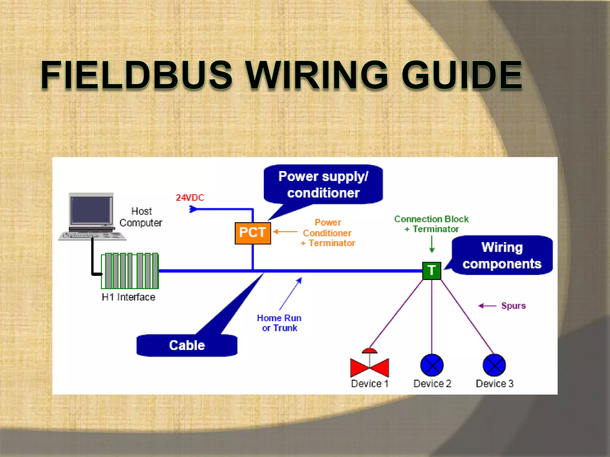
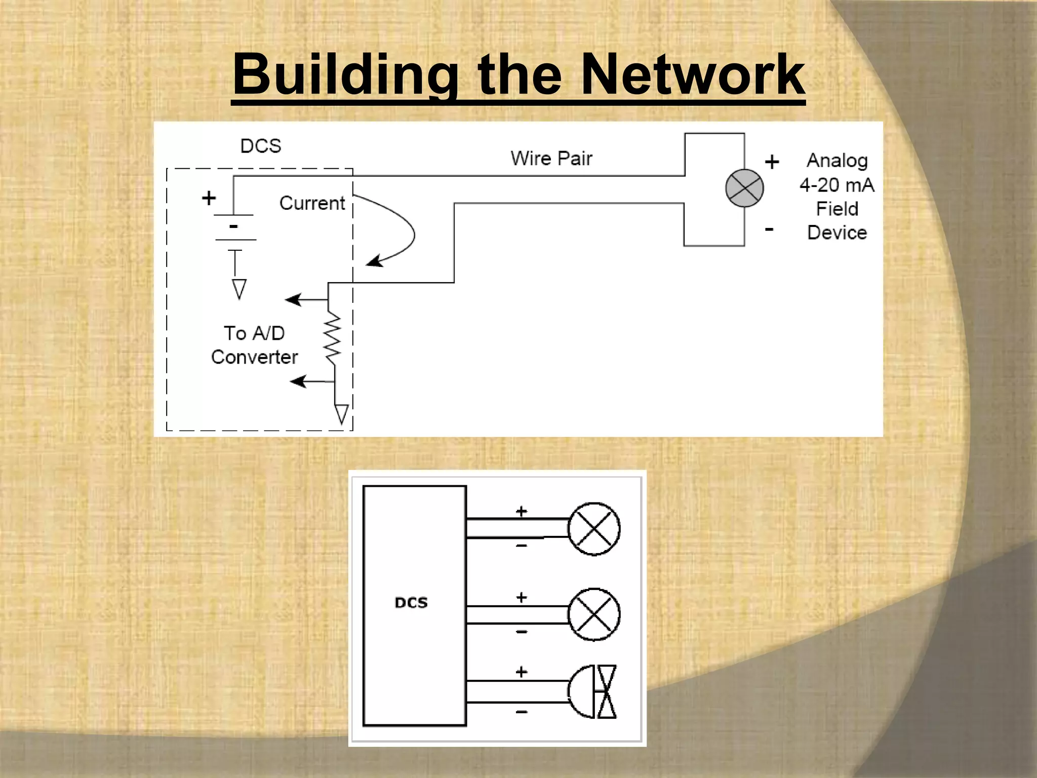
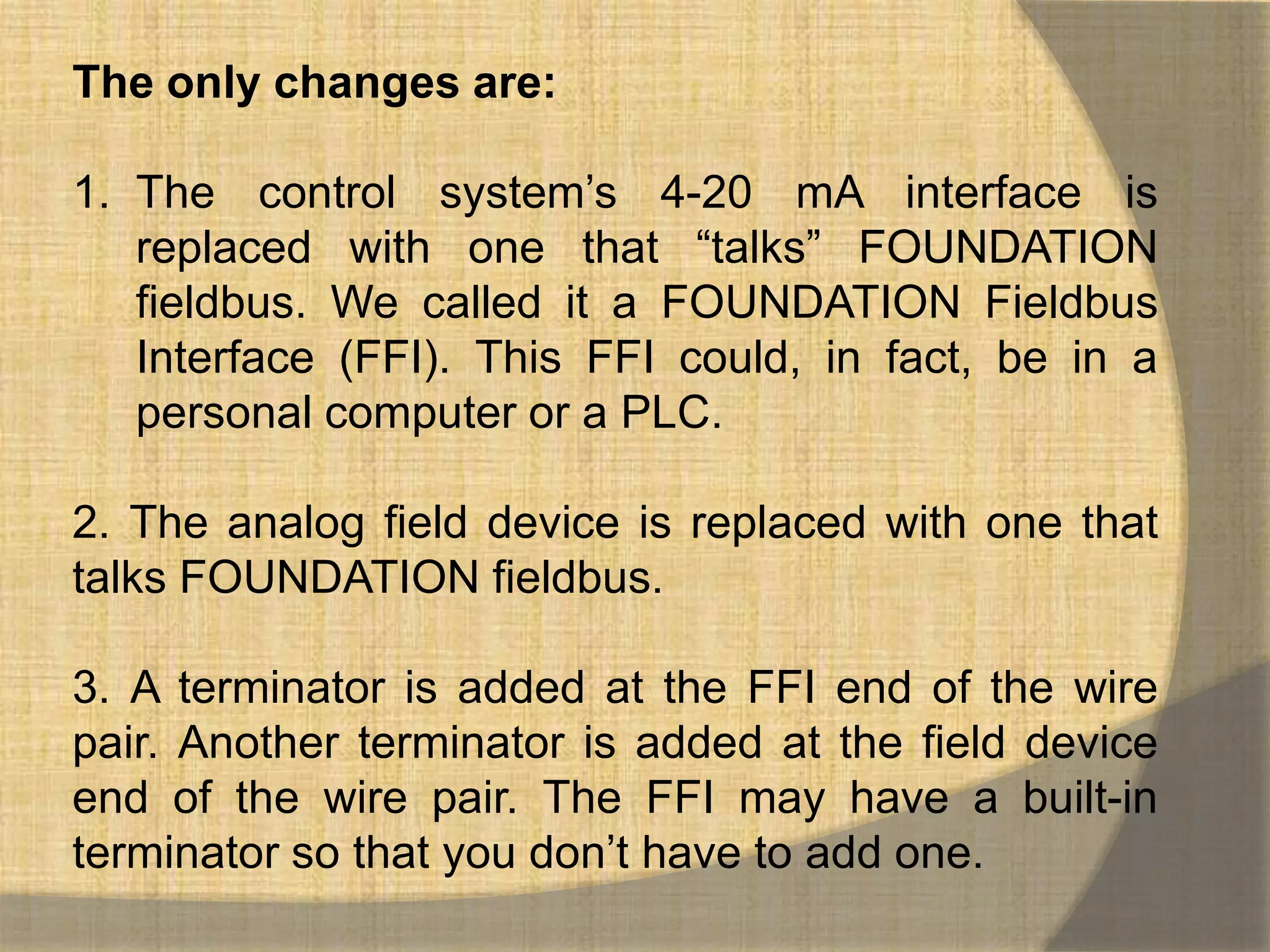
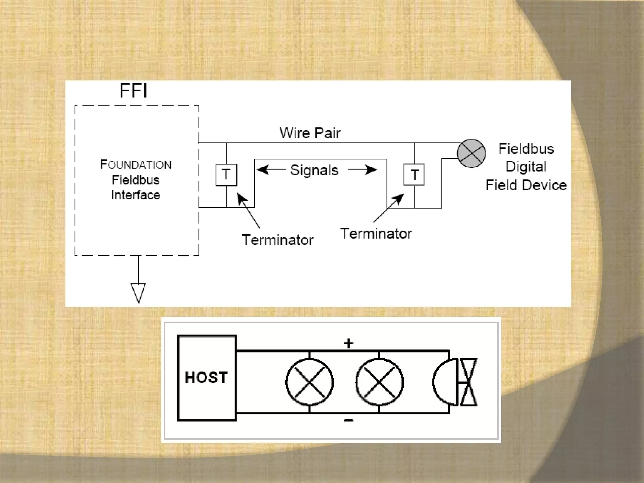
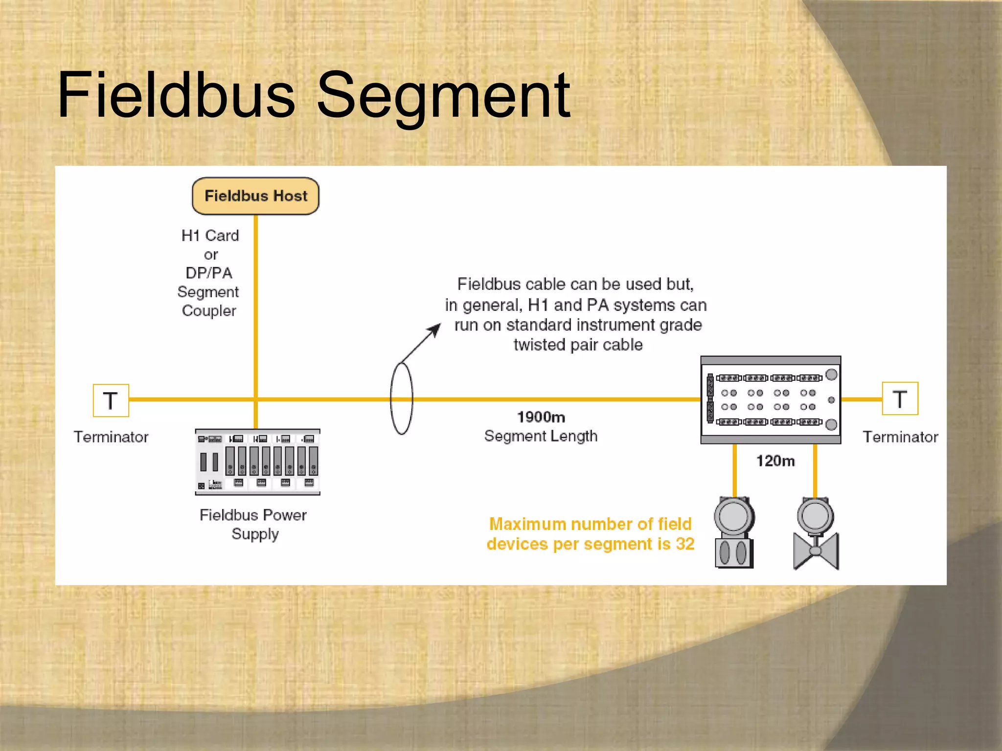
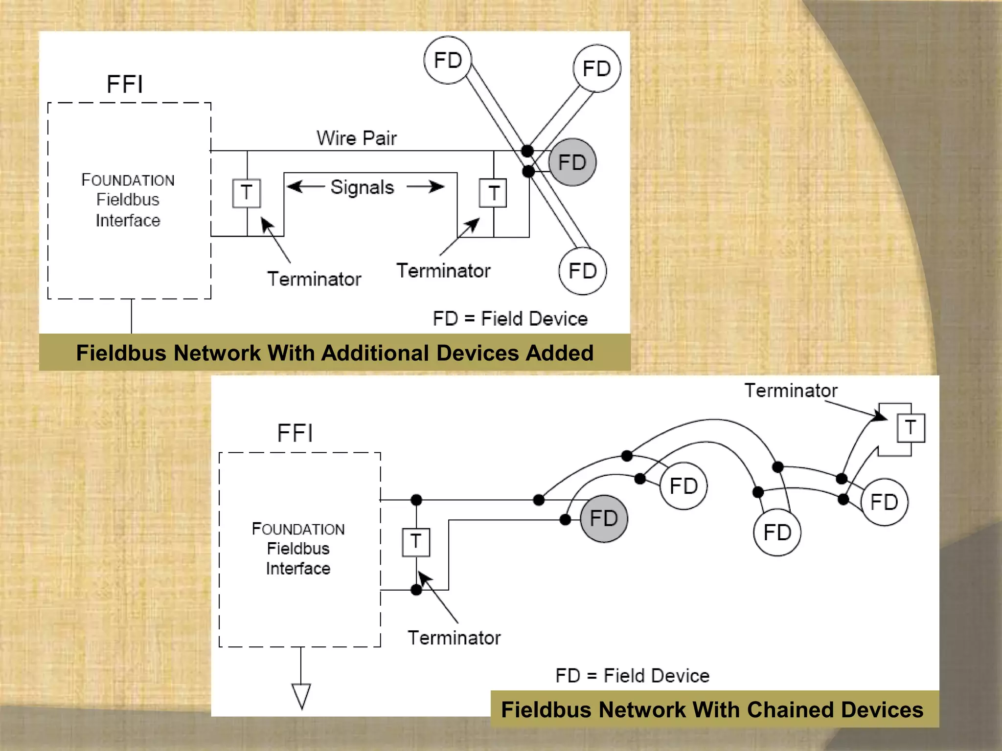
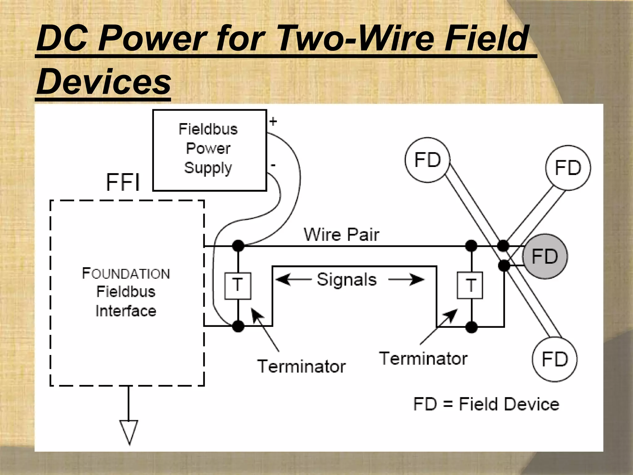
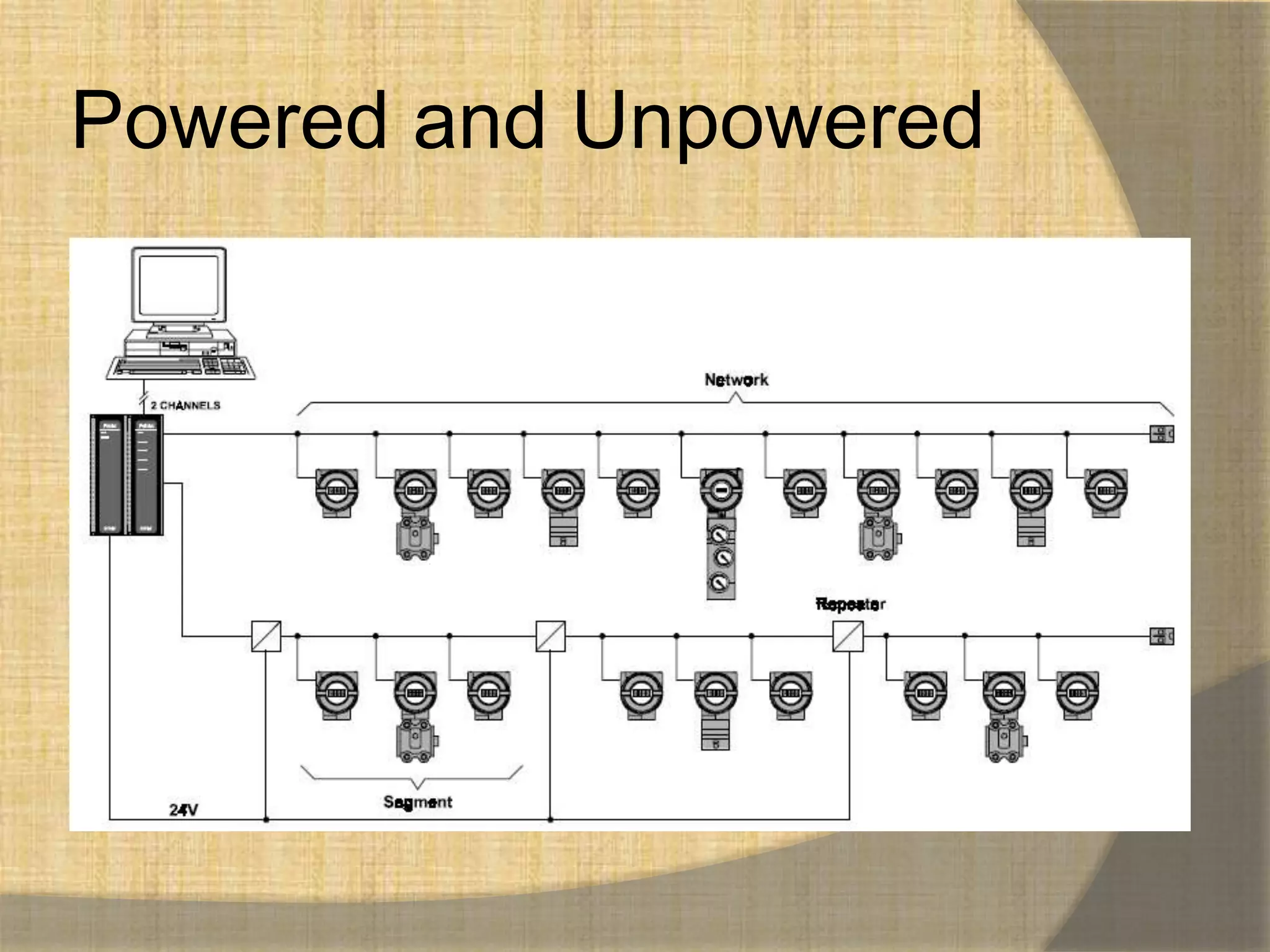
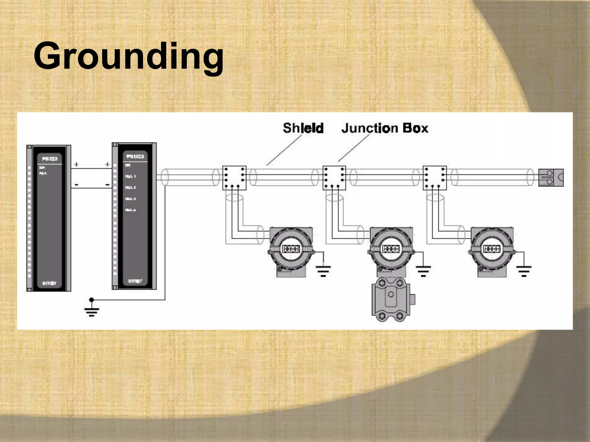


1. Fieldbus networks replace traditional 4-20 mA analog signals with digital communication over twisted-pair wiring. 2. The key changes are replacing the analog control system and field devices with digital ones that communicate over FOUNDATION fieldbus, and adding terminators to the wire pairs. 3. Devices can be connected in a bus, tree, daisy chain, or point-to-point topology with optional repeaters, bridges or gateways to extend the network or connect different segments.


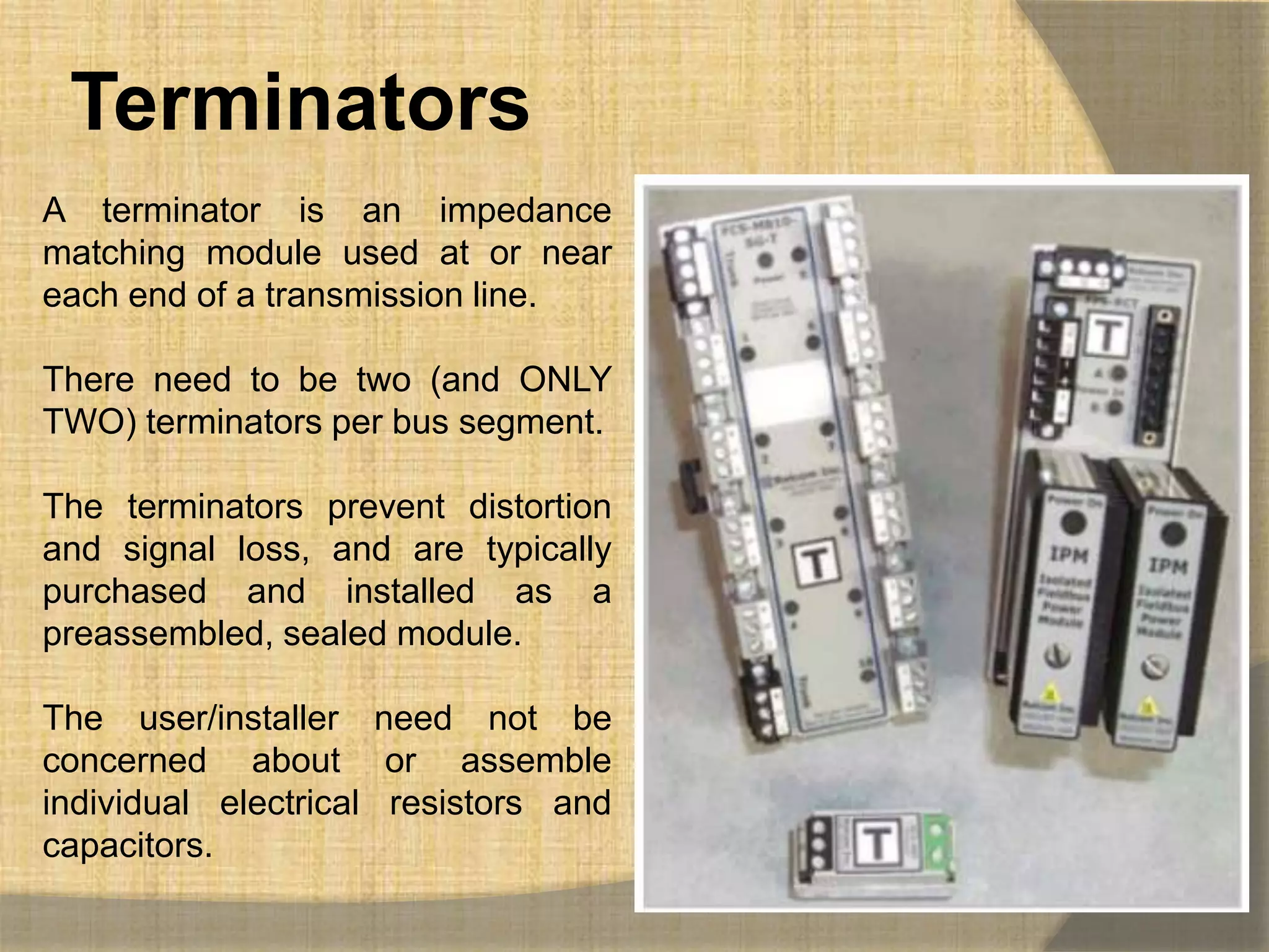
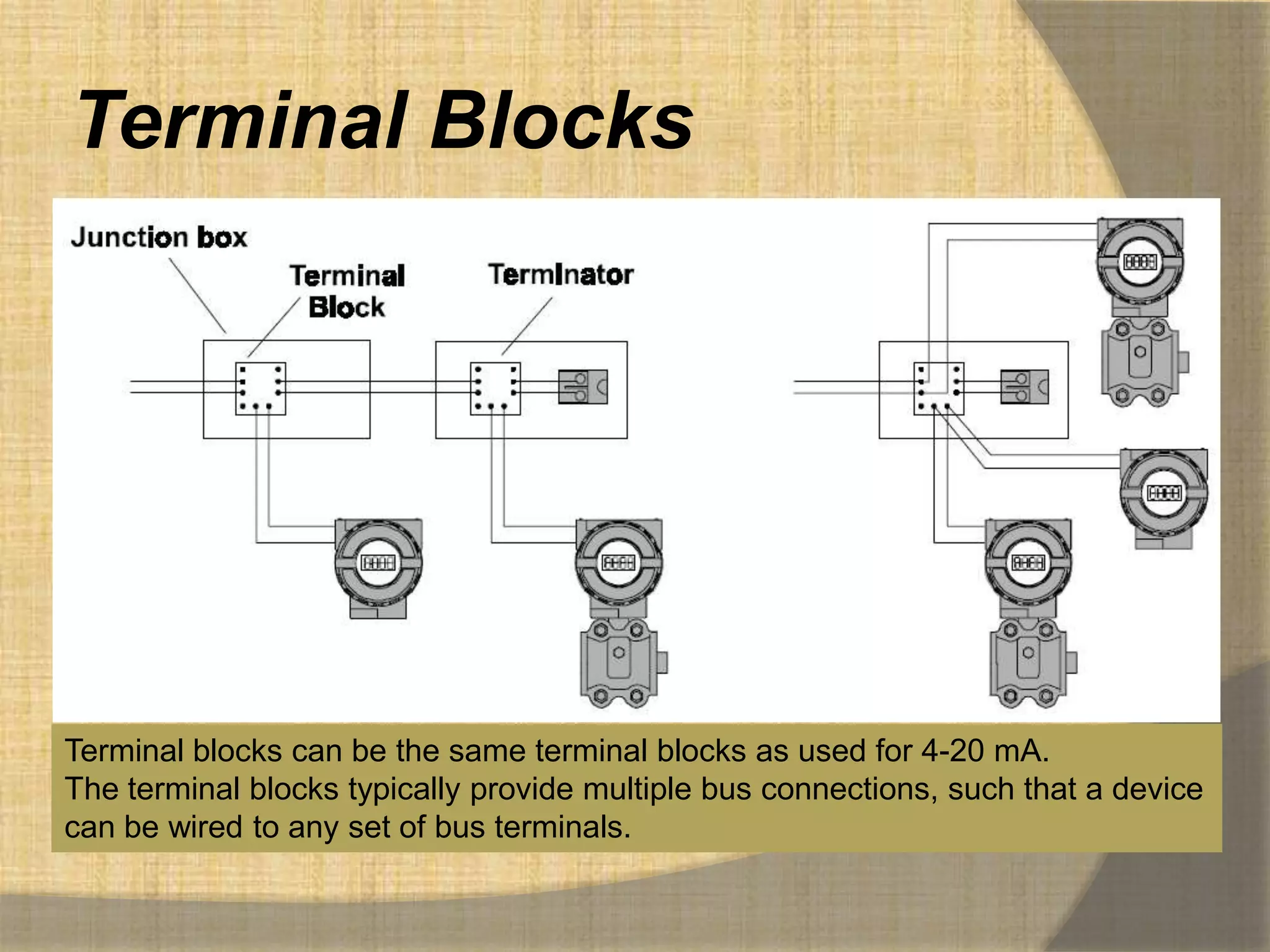
![Using%20 modbus%20for%20process[1]](https://cdn.slidesharecdn.com/ss_thumbnails/using20modbus20for20process1-140402073109-phpapp01-thumbnail.jpg?width=640&height=640&fit=bounds)


