Downloaded 1,320 times
![Slide No 5
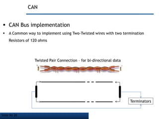
CAN – “Bus Topology”
What is a Network Topology
It is the arrangement of various elements [Links, Nodes, Etc.]
for a Network [a telecommunication n/w] to exchange Data
So CAN is a BUS Topology](https://image.slidesharecdn.com/controlledareanetworkbasic1-140710022319-phpapp01/85/Controller-Area-Network-Basic-Level-Presentation-5-320.jpg)
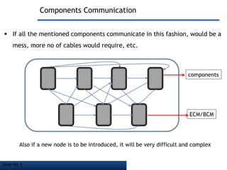
![Slide No 6
Vehicle Bus Topology
What is a Vehicle Bus
An internal communications network that interconnects components inside a
vehicle [e.g. automobile, bus, train, industrial or agricultural vehicle, etc.]
components
Internal Communication
Network](https://image.slidesharecdn.com/controlledareanetworkbasic1-140710022319-phpapp01/85/Controller-Area-Network-Basic-Level-Presentation-6-320.jpg)
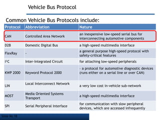
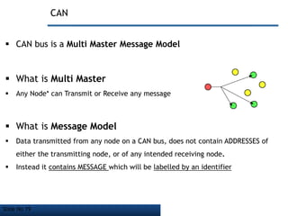
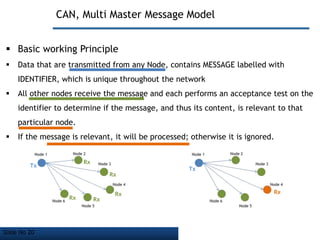


The document discusses Controller Area Network (CAN) bus, which is a vehicle bus standard that allows microcontrollers and devices to communicate with each other within a vehicle without a host computer. Key points: - CAN bus uses a serial communication protocol and multi-master message model to allow nodes to transmit and receive messages. - It employs a bus topology where nodes are connected to a single cable with termination resistors at each end to eliminate signal reflections. - CAN bus is used widely in automotive applications but also in other industries like shipping, manufacturing, etc. due to its robustness, error detection and flexibility.


