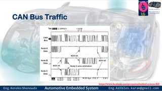
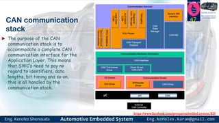
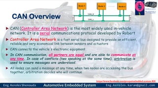
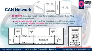
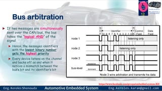
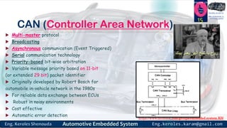
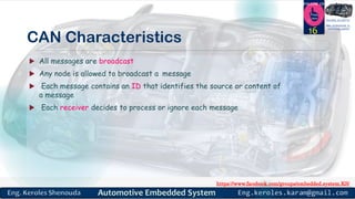
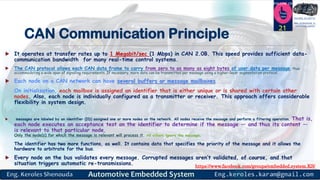
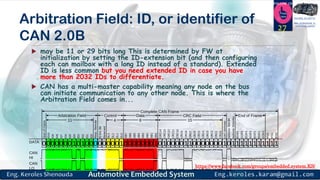
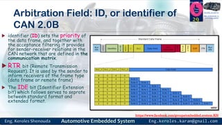
Controller Area Network (CAN) is a serial communication protocol that is most commonly used in automotive applications. It allows microcontrollers and devices to communicate with each other in real-time. CAN uses a multi-master broadcast communication style where nodes can transmit messages at any time and all nodes receive all messages. It uses priority-based arbitration to determine which message is transmitted when two nodes transmit simultaneously. CAN provides efficient, reliable, and economical communication between sensors, actuators and electronic control units in automotive and other embedded systems applications.


![https://www.facebook.com/groups/embedded.system.KS/
Follow us
Press
here
#LEARN_IN DEPTH
#Be_professional_in
embedded_system
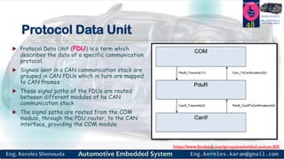
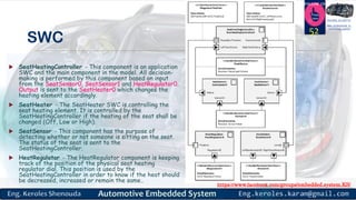
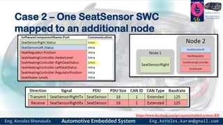
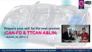
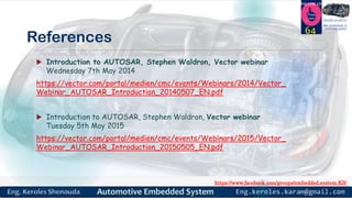
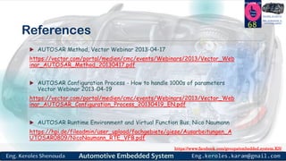
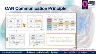
Bit Rate / Bus Length
1M bit/sec 40 meters (131 feet)
500K bit/sec 100 meters (328 feet)
250K bit/sec 200 meters (656 feet)
125K bit/sec 500 meters (1640 feet)
11
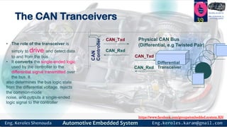
Bus lines
assumed to be
an electrical
medium
(e.g. twisted pair)
40 100 1000 10,000
CAN Bus Length [m]
0 10 200
1000
500
10
5
Bit Rate
[kbps]
20
50
200
100](https://image.slidesharecdn.com/automotiveembeddedsystemspart7v1-180403092053/85/Automotive-embedded-systems-part7-v1-11-320.jpg)
![https://www.facebook.com/groups/embedded.system.KS/
Follow us
Press
here
#LEARN_IN DEPTH
#Be_professional_in
embedded_system
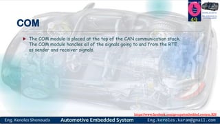
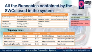
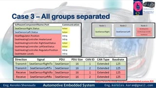
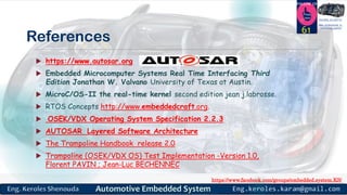
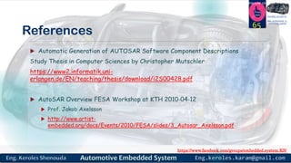
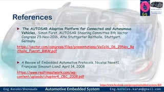
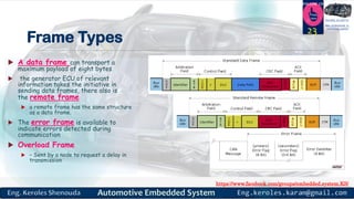
Data Flow in CAN
Transmitting Node
MCU Firmware
Identifier [id_n]
Data [values_x]
CAN Peripheral
Tx Mail Box [id_n]
Data [values_x]
Rx Mail Box [id_c]
Rx Mail Box [id_b]
CAN Transceiver
Node Configured to
receive identifier
MCU Firmware
Identifier [id_n]
Data [values_x]
CAN Peripheral
Data [values_x]
CAN Transceiver
Rx Mail Box [id_c]
Rx Mail Box [id_b]
Rx Mail Box [id_n]
Node not Configured to
receive identifier
MCU Firmware
CAN Peripheral
CAN Transceiver
Rx Mail Box [id_d]
Rx Mail Box [id_b]
Rx Mail Box [id_c]
Rx Mail Box [id_a]
Data Frame is broadcast to the bus ][value ]id n_[ x_
17](https://image.slidesharecdn.com/automotiveembeddedsystemspart7v1-180403092053/85/Automotive-embedded-systems-part7-v1-17-320.jpg)
![https://www.facebook.com/groups/embedded.system.KS/
Follow us
Press
here
#LEARN_IN DEPTH
#Be_professional_in
embedded_system
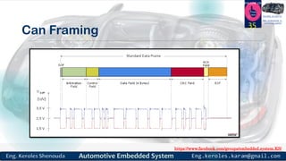
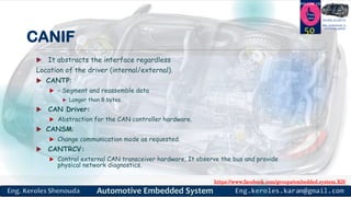
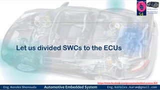
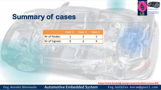
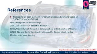
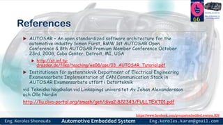
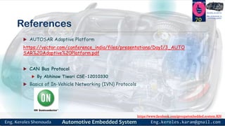
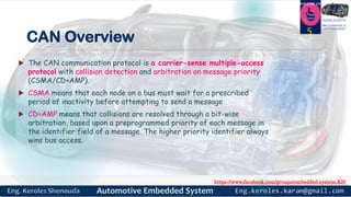
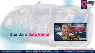
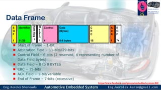
Start Of Frame [SOF]
SOF: CAN has a multi-master capability, meaning any node on the bus
can initiate communication to any node configured to receive. This is
done with a Start of Frame. A single dominant bit while the bus is idle
indicates a transmitting node is starting a frame.
All nodes on the bus will synchronize their bit timing to the leading
edge of SOF.
26](https://image.slidesharecdn.com/automotiveembeddedsystemspart7v1-180403092053/85/Automotive-embedded-systems-part7-v1-26-320.jpg)

![https://www.facebook.com/groups/embedded.system.KS/
Follow us
Press
here
#LEARN_IN DEPTH
#Be_professional_in
embedded_system
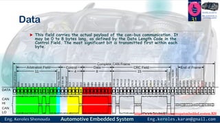
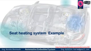
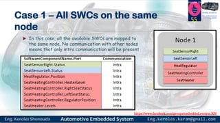
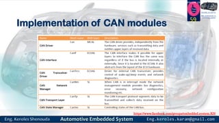
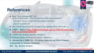
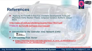
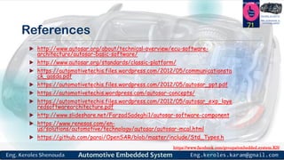
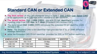
Control Field
The Control Field consists of six bits
- 1 are reserved
- 4 are the Data Length Code which indicates number of data bytes in
the data field [0-8 bytes being valid sizes]
- DLC codes not shown in the figure are reserved
30](https://image.slidesharecdn.com/automotiveembeddedsystemspart7v1-180403092053/85/Automotive-embedded-systems-part7-v1-30-320.jpg)