Downloaded 157 times


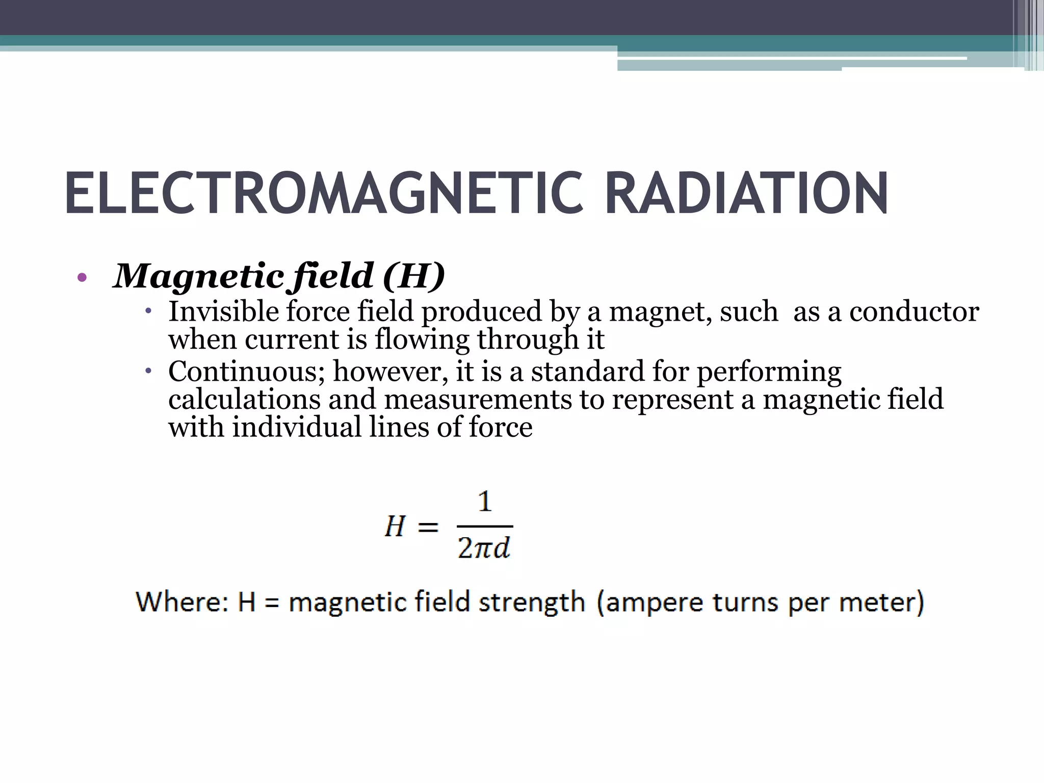


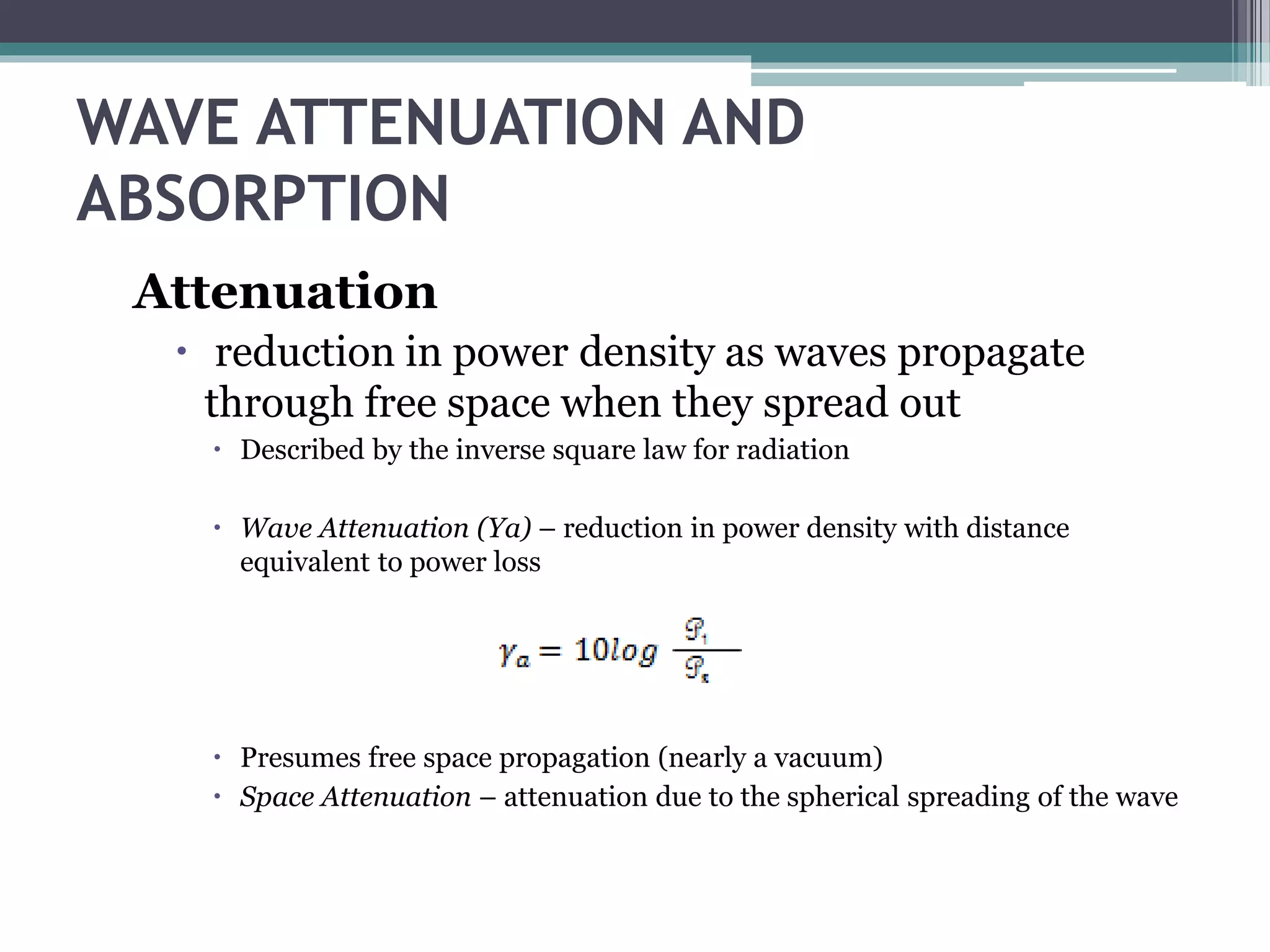


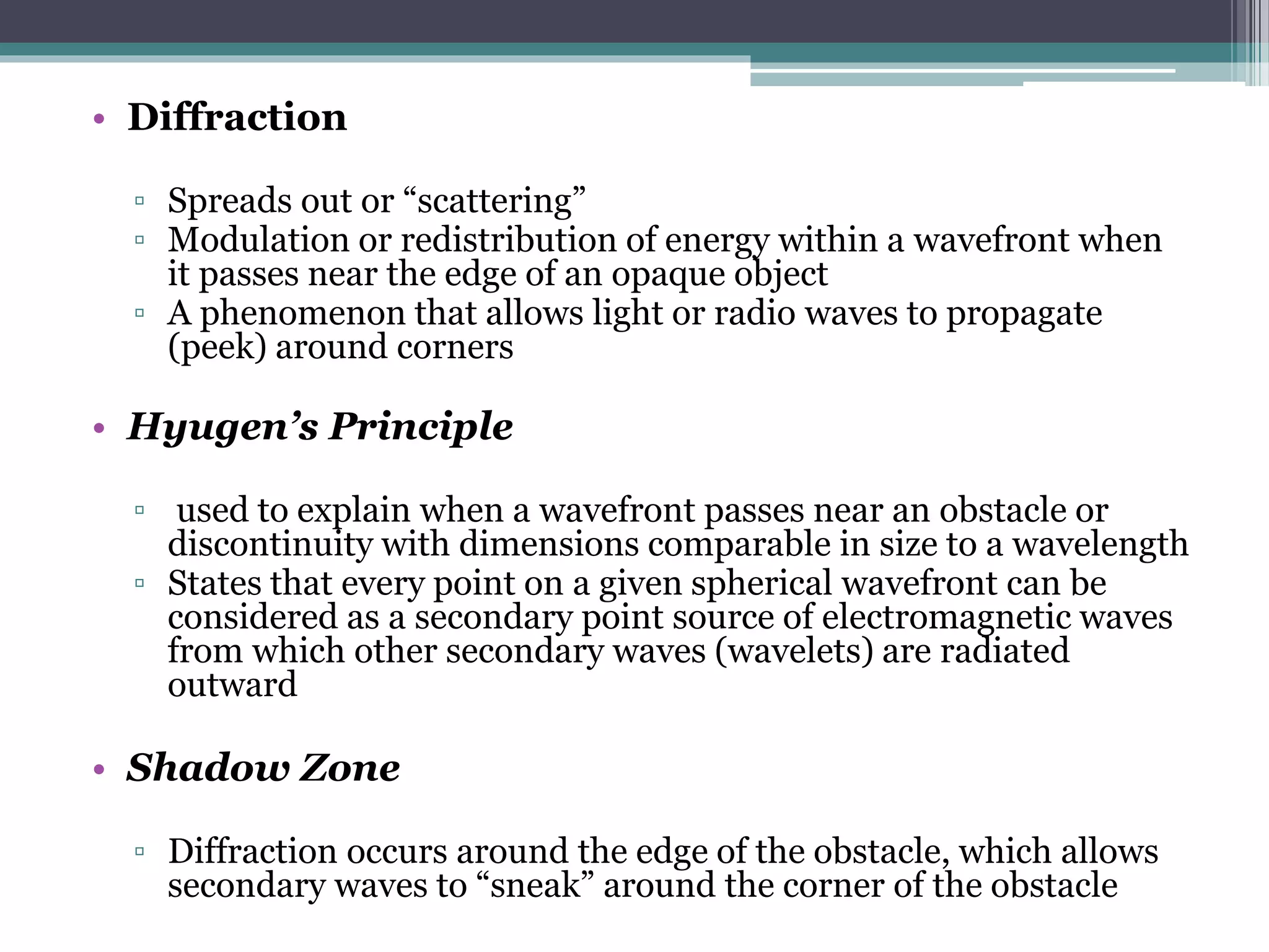


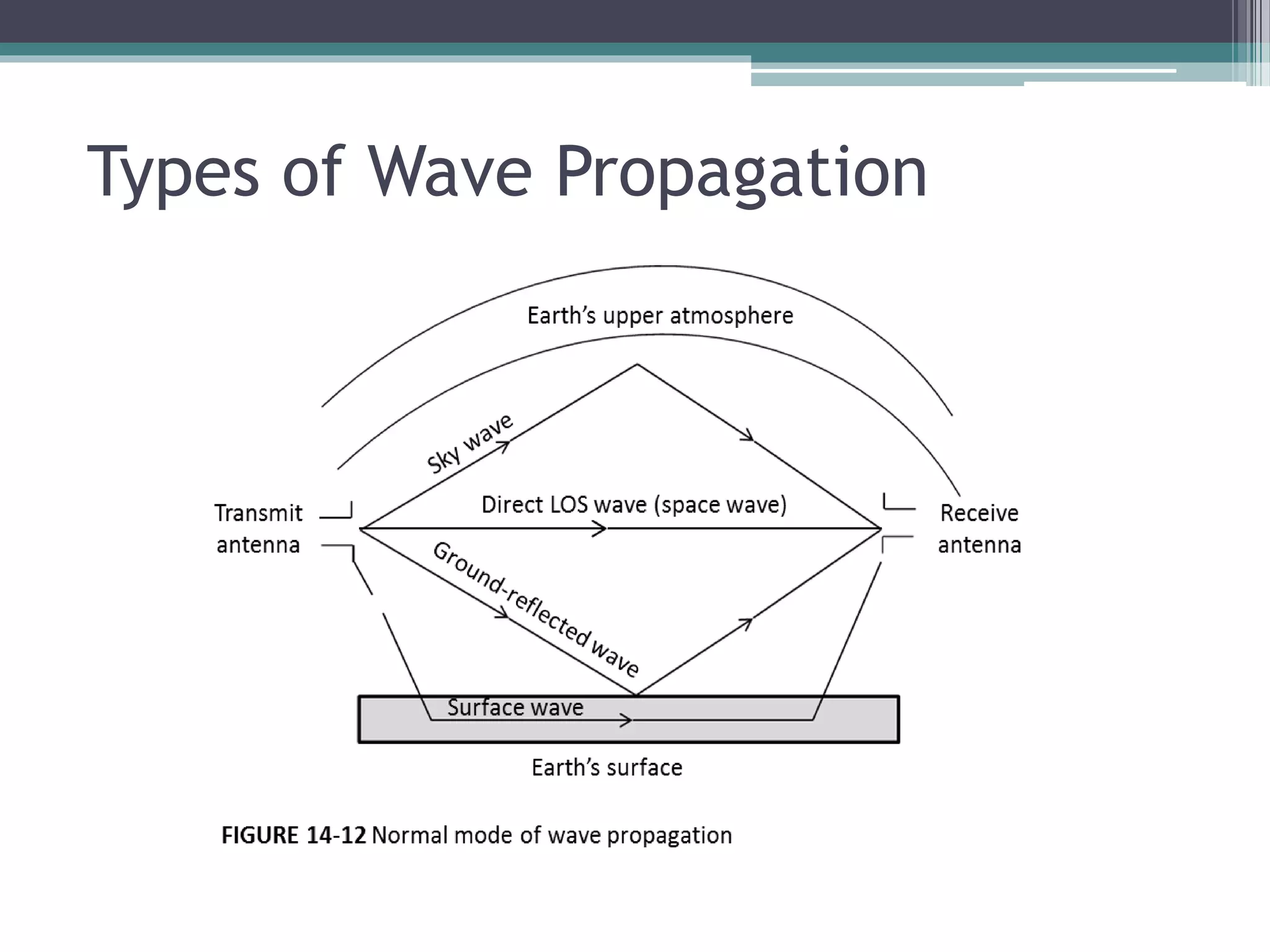


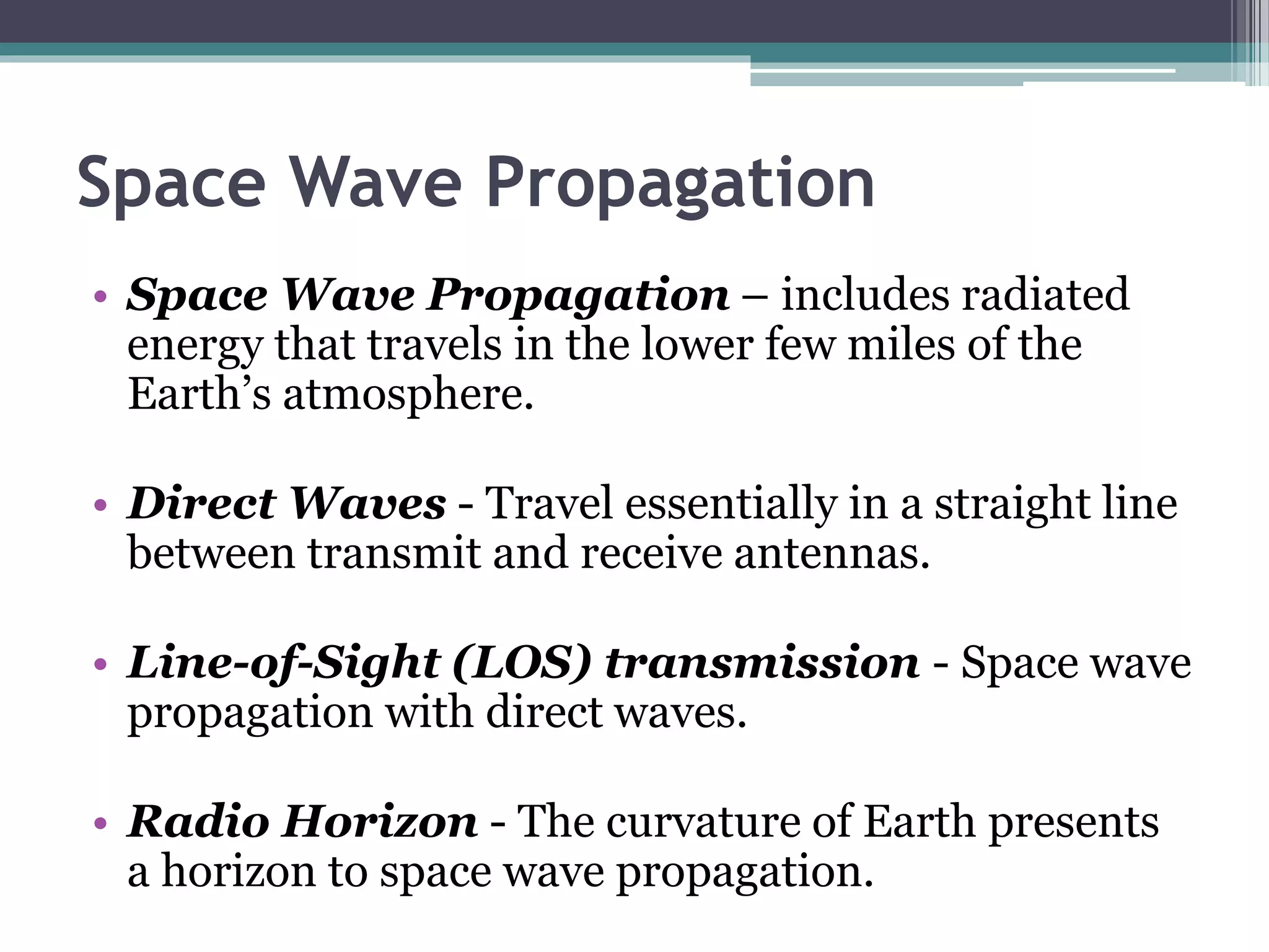

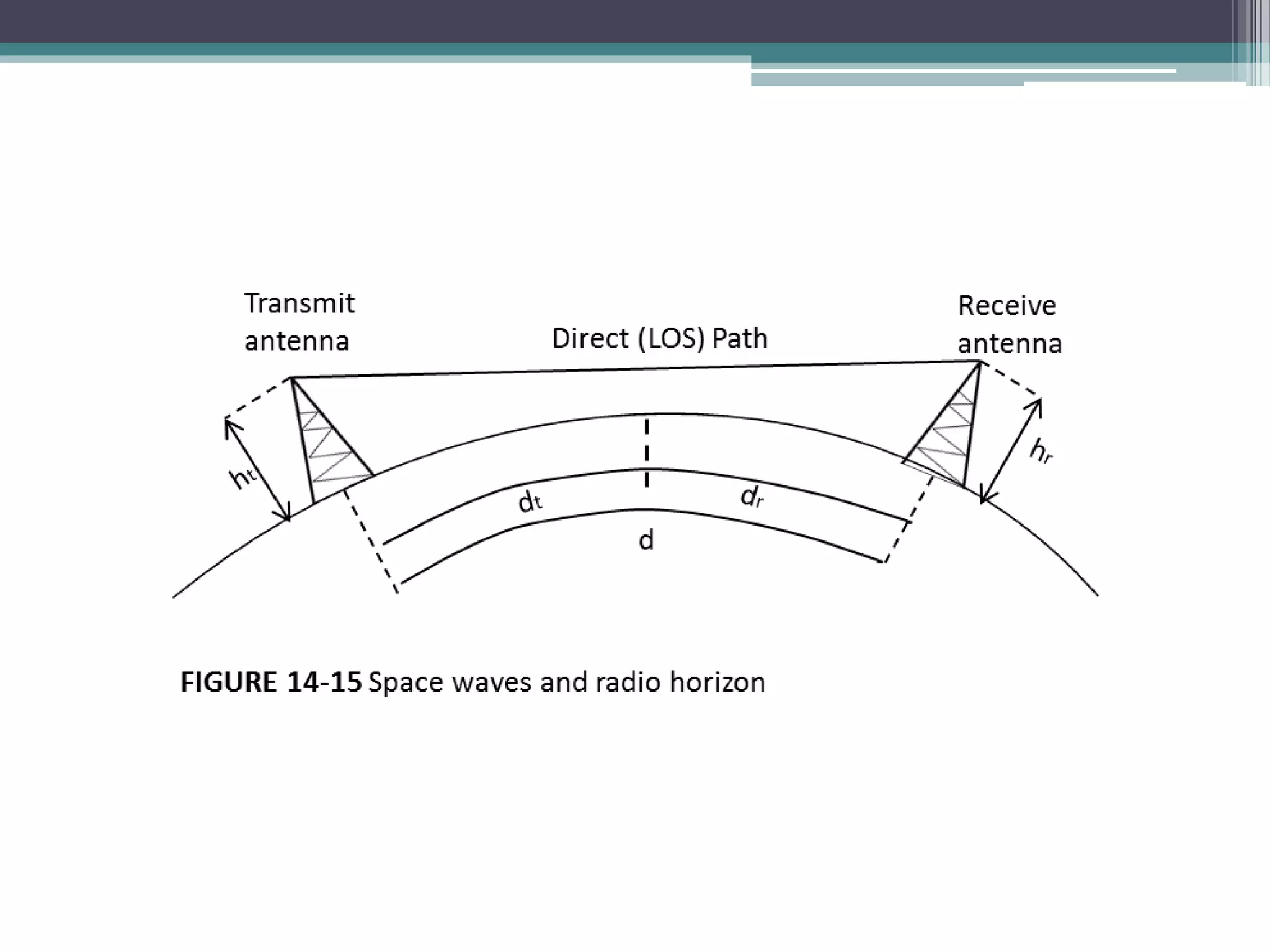
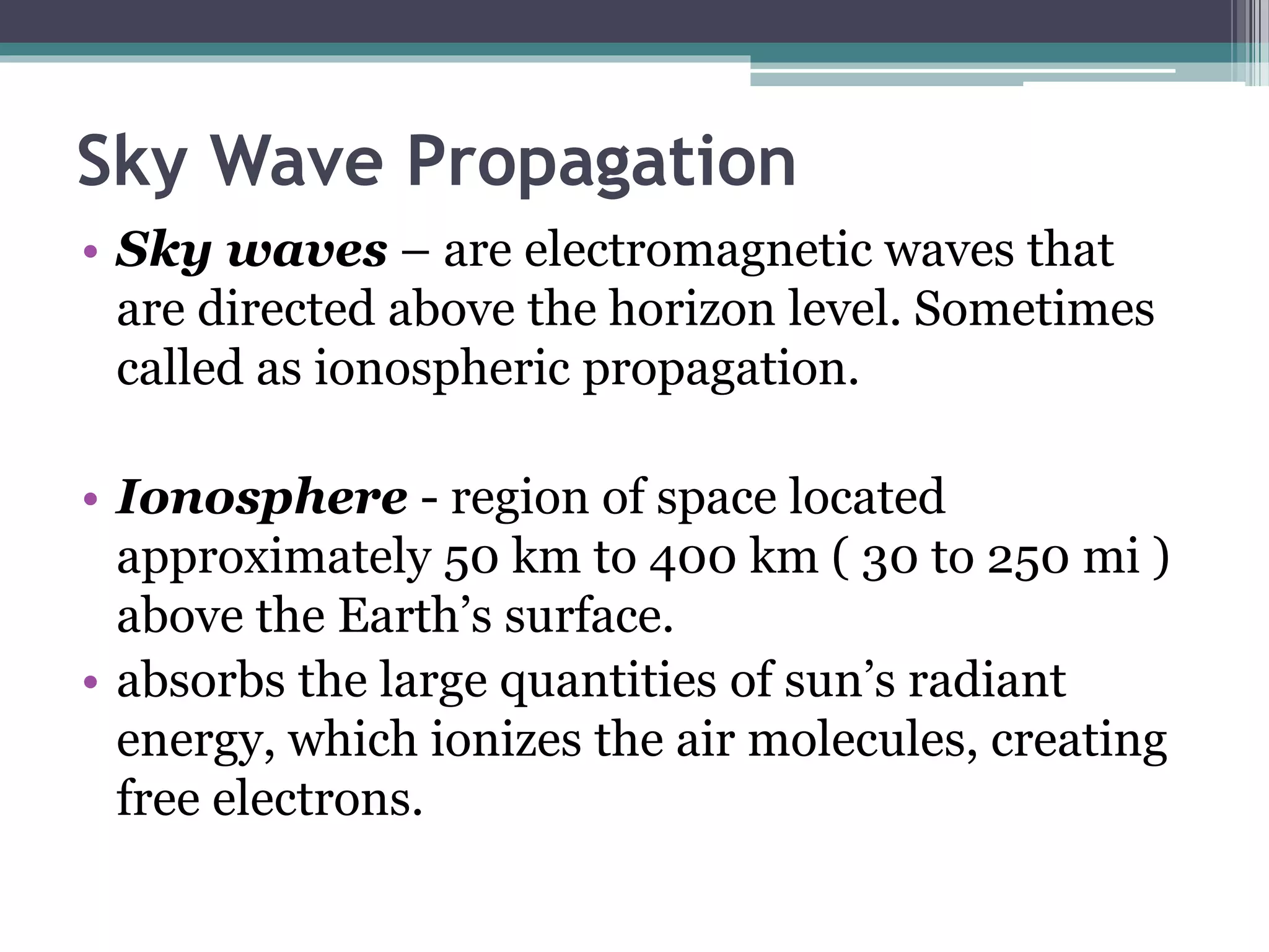


This document discusses electromagnetic wave propagation. It begins by defining electromagnetic waves and their properties like frequency, intensity, and direction of travel. It then discusses different types of electromagnetic waves like radio waves. Key concepts covered include polarization, rays and wavefronts, the electric and magnetic fields, characteristic impedance, inverse square law, attenuation, refraction, reflection, diffraction, interference, and terrestrial propagation through surface waves and sky waves. Sky wave propagation is explained in detail, covering the ionosphere layers, critical frequency, critical angle, virtual height, and skip distance.


![3_Antenna Array [Modlue 4] (1).pdf](https://cdn.slidesharecdn.com/ss_thumbnails/3antennaarraymodlue41-220419112111-thumbnail.jpg?width=640&height=640&fit=bounds)