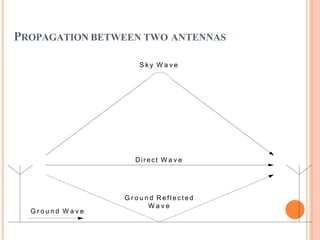
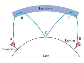
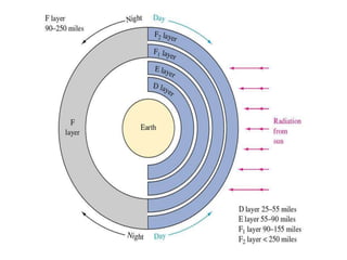
A
PRESENTATION
ON
W
A
VE PROPAGATION
MAXWELL'S EQUATIONS
 Electrical field lines may either start and end on
charges, or are continuous in nature.
 Magnetic field lines are continuous in nature.
 An electric field is produced by a time-varying
magnetic field
 A magnetic field is produced by a time-varying
electric field or by a current
The higher frequencies:
The more radio waves resamble the properties of
light
At lower frequencies:
Electrical properties of obstacles are important but
we tend to express these in terms of optical
properties
If the wave length is of the same order of
magnitude, diffraction or surface effects dominate
PROPAGATION MECHANISMS
MODES OF PROPAGATION
 Ground wave propagation
 Space wave propagation
 Sky wave propagation
 Tropospheric scattering propagation
PROPAGATION BETWEEN TWO ANTENNAS
Direct W a v e
G r o u n d R e f l e c t e d
W a v e
G r o u n d W a v e
S k y W a v e
ELECTRICAL TO MAGNETIC CONVERSION
 The antennas are the transducers
The transmitting antenna changes the electrical
energy into electromagnetic or waves
The receiving antenna changes the electromagnetic
energy back into electrical energy
 These electromagnetic waves propagate at
rates ranging from 150kHz to 300GHz
ELECTROMAGNETIC WAVES
 Consist of
Magnetic wave
Electrical wave
 Most of the energy is returned to the circuit.
 If it isn’t, then some it must be “set free” or radiated.
Radiated energy is not desirable.
TRANSVERSE WAVES
 Transverse waves are those whose direction of
propagation is perpendicular to
electrical field and the magnetic
both the
field The
electrical field and the magnetic fields lie in
planes that are perpendicular to each other.
 Thus the direction of propagation will be in the z
plane or third dimension
POLARIZATION OF THE ELECTRICAL FIELD
 The polarization of the electrical field is determined by the
direction of oscillations.
If the oscillations are in the vertical direction then the polarization is said to
be vertical.
If the oscillations are in the horizontal direction then the is said to be
horizontal.
 Thus a “vertical” antenna will result in a vertically polarized
wave.
 A vertical antenna is one that consists of a vertical tower, wire, or
rod, usually a quarter wavelength in length that is fed at the
ground and uses the ground as a reflecting surface.
WAVEFRONTS
 A wavefront is a Plane joining all points of equal phase in a
wave.
 Take a point in space. Imagine waves radiating outward in all
directions from this point. The result would resemble a
sphere. The point of radiation is called the isotropic point
source.
 Since the power at any point away from the isotropic point is
inversely proportional to the square of the distance from the
point, then the power decreases rapidly the further away from
the point you need.
 Although the wavefront is curved in shape, from a distance
small sections appear planar and can be thought of as plane
wavefronts.
CHARACTERISTIC IMPEDANCE OF FREE SPACE
 In free space:
= 1.26 x 10⁻⁶ H/m
= 8.85 x 10⁻¹² F/m
= 377
FOUR TYPES OF WAVES
Incident
Reflected
Refracted
Diffracted
REFLECTION
 Reflection is the abrupt reversal in direction.
 Caused by any conductive medium such as
Metal surface
Earth’s surface
 There will normally be a shift in phase
 Coefficient of reflection is less than 1
COMPLETE REFLECTION
 Complete reflection will occur only in perfect conductors
and when the electric field is perpendicular to the
reflecting element or medium
 Coefficient of Reflection will be 1
 Coefficient of Reflection is the ratio of the reflected
wave intensity to the incident wave intensity
RADIO-FREQUENCY INTERFERENCE
 If the radiated energy comes from another radio
transmitter, then it is considered Radio- Frequency
Interference (RFI)
 The transmitting antenna should be specifically
designed to prevent the energy from being
returned to the circuit.
 It is desirable that the antenna “free” the energy in
order that it might radiate into space
ELECTRICAL FIELDS PARALLEL TO THE
CONDUCTOR
 When the E fields are parallel to the conductor or
conducting medium, the electrical energy is absorbed by the
medium thus acting like a short
REFRACTION
 Occurs when the waves pass from one medium to another
whose densities are different
 Coefficient of reflection is less than 1
 The angle of incidence and the angle of refraction is
related by Snell’s Law
DIFFRACTION
 Waves traveling in straight lines bend around
obstacles
 Based on Huygen’s principle (1690)
Each point on a wavefront can be thought of as an
isotropic point or a source of secondary spherical energy
 Concepts explains why radio waves can be heard
behind tall mountains or buildings that are normally
considered to block line of sight transmissions
Ground and Space Waves
GROUND WAVES
 Radio wave that travels along the earth’s surface (surface
wave)
 Vertically polarized
 Changes in terrain have strong effect
 Attenuation directly related to surface impedances
More conductive the more attenuated
Better over water
 Attenuation related to frequency
Loses increase with increase in frequency
Not very effective at frequencies above 2Mhz
Very reliable communication link
Reception is not affected by daily or seasonal weather changes
 Used to communicate with submarines
 ELF (30 to 300 Hz) propagation is utilized
FIGURE 12-6 DIRECT AND GROUND REFLECTED SPACE WAVES.
Gary M. Miller, Jeffrey S. Beasley
Modern Electronic Communication, 7e
Copyright ©2002 by Pearson Education, Inc.
Upper Saddle River, New Jersey 07458
All rights reserved.
SPACE WAVE
 Two types
Direct
Ground reflected
DIRECT
 Limited to “line-of sight” transmission distances
 Antenna height and curvature of earth are
factors
limiting
 Radio horizon is about 80% greater than line of sight
because of diffraction effects
FIGURE 12-7 RADIO HORIZON FOR DIRECT SPACE WAVES.
Gary M. Miller, Jeffrey S. Beasley
Modern Electronic Communication, 7e
Copyright ©2002 by Pearson Education, Inc.
Upper Saddle River, New Jersey 07458
All rights reserved.
REFLECTED
 Part of the signal from the transmitter is bounced off the
ground and reflected back to the receiving antenna
 Can cause problems if the phase between the direct wave
and the reflected wave are not in phase
 Detuning the antenna so that the reflected wave is too
weak to receive
Sky Waves
FIGURE 12-9 SKY-WAVE PROPAGATION.
Gary M. Miller, Jeffrey S. Beasley
Modern Electronic Communication, 7e
Copyright ©2002 by Pearson Education, Inc.
Upper Saddle River, New Jersey 07458
All rights reserved.
SKY WAVE
 Radio waves radiated from the transmitting
antenna in a direction toward the ionosphere
 Long distance transmissions
 Sky wave strike the ionosphere, is refracted
back to ground, strike the ground, reflected
back toward the ionosphere, etc until it
reaches the receiving antenna
 Skipping is he refraction and reflection of sky
waves
ATMOSPHERIC PHENOMENON
 Three layers:
Troposphere: earth’s surface to about 6.5 mi
Stratosphere: extends from the troposphere upwards for about
23 mi
Ionosphere: extends from the stratosphere upwards for about
250mi
Beyond this layer is free space
FIGURE 12-10 LAYERS F THE IONOSPHERE.
Gary M. Miller, Jeffrey S. Beasley
Modern Electronic Communication, 7e
Copyright ©2002 by Pearson Education, Inc.
Upper Saddle River, New Jersey 07458
All rights reserved.
STRATOSPHERE
 Temperature in the stratosphere is believed to be fairly
constant and is not subject to temperature changes or
inversions and will not cause significant refractions
 This is called an isothermal region
 The ionic density in the ionosphere varies
from very dense at the border between the
ionosphere and stratosphere to very low
density as it approaches free space
 The ions in the far reaches of the ionosphere
are easily susceptible to the sun’s radiation
with the susceptibility reducing as one
approaches the stratosphere
IONOSPHERE
 Three layers
D: low frequencies can be refracted but the high frequencies
tend to pass on through
E: signals as high as 20MHz can be refracted while higher
ones pass through
F: during the day light hours there are two layers:
 F1 and F2
 F: during the night hours the ionization
layer is relatively constant and the higher
frequencies can be refracted
 During the night hours, the D and E layers
virtually disappear and signals that would be
refracted at lower levels now are refracted
at higher levels.
 This results in greater skip distances and
better reception at greater distances than in
the daytime hours.
IONOSPHERE
 The layers that form the ionosphere vary greatly in
altitude, density, and thickness with the varying
degrees of solar activity.
 The upper portion of the F layer is most affected
by sunspots or solar disturbances
 There is a greater concentration of solar radiation
during peak sunspot activity.
 The greater radiation activity the more dense the F
layer and the higher the F layer becomes and the
greater the skip distance
FIGURE 12-11 RELATIONSHIP OF FREQUENCY TO REFRACTION BY THE IONOSPHERE.
Gary M. Miller, Jeffrey S. Beasley
Modern Electronic Communication, 7e Upper Saddle River, New Jersey 0745
Copyright ©2002 by Pearson Education, Inc.
8
.
All rights reserved
FIGURE 12-12 RELATIONSHIP OF FREQUENCY TO CRITICAL ANGLE.
Gary M. Miller, Jeffrey S. Beasley
Modern Electronic Communication, 7e
Copyright ©2002 by Pearson Education, Inc.
Upper Saddle River, New Jersey 07458
All rights reserved.
SOLAR CYCLE
 Every 11 years the sun undergoes a period of activity called
the "solar maximum", followed by a period of quiet called
the "solar minimum".
 During the solar maximum there are many sunspots, solar
flares, and coronal mass ejections, all of which can affect
communication The Sun goes through a periodic rise and fall
in activity which affects HF communications; solar cycles
vary in length from 9 to 14 years.
 At solar minimum, only the lower frequencies of the HF
band will be supported by the ionosphere, while at solar
maximum the higher frequencies will successfully
propagate, figure 1.4. This is because there is more radiation
being emitted from the Sun at solar maximum, producing
more electrons in the ionosphere which allows the use of
higher frequenciesand weather here on Earth.
•
 One way we track solar activity is by observing sunspots.
Sunspots are relatively cool areas that appear as dark
blemishes on the face of the sun. They are formed when
magnetic field lines just below the sun's surface are twisted
and poke though the solar photosphere. The twisted
magnetic field above sunspots are sites where solar flares
are observed to occur, and we are now beginning to
understand the connection between solar flares and
sunspots.
During solar maximum there are many sunspots,
and during solar minimum there are few. The plot
at right shows the number of sunspots observed
during the last two solar cycles. The last maximum
occurred around 1989, and the next is predicted to
fall in the year 2000. This plot is updated monthly.
Click here for a plot of sunspot numbers from the
year 1749 through the present.
HOW DO SUNSPOTS AFFECT EARTH
 The Earth is affected by both solar flares and
sunspots. Solar flares emit high-speed particles
which cause auroras, known in the northern
hemisphere as Northern Lights. The image
shown here is a real-time satellite image of the
Earth's auroral region above the North Pole. From
the ground auroras appear as shimmering
curtains of red and green light in the sky.
HOW DOES HF RADIO WORK OVER LONG DISTANCES?
 An HF signal transmitted from the earth may travel som
way through the ionosphere before being "bent" back down
towards the ground. This occurs due to the interaction
between the HF signal and electrically charged particles in
the ionosphere. The signal can then "bounce" off the
ground back into the ionosphere, return to the earth again,
and so on. The distance a given HF signal will travel
depends on the frequency, transmitter power, take-off
angle relative to the ground and the state of the
ionosphere through which it is travelling.
e
 For any given distance and time, there will be a certain
range of HF frequencies that are most likely to provide
successful communications; frequencies outside that range
will work poorly or not at all. Simply increasing the power of
an HF signal will not help if the frequency is too high for the
distance required. Increasing the power may help if the
frequency is too low, but using a higher, more suitable
frequency is the best option. The highest frequency which
may be used for reliable HF communications is known as
the Maximum Usable
Frequency (MUF).
HOW DO CONDITIONS AFFECTING THE USE OF
HF RADIO VARY OVER TIME?
 Extreme Ultraviolet (EUV) radiation from the sun creates the
ionosphere. The EUV radiation arises from the bright and
hot regions which overlie sunspots (areas of strong
magnetic fields on the sun's surface). As the sun
progresses through its eleven year cycle of activity, the
number and size of sunspots will vary, as will the level of
EUV radiation. Changes to the ionosphere that result from
this mean that conditions affecting the use of HF radio will
also change over the solar cycle.
 At the low point of the solar cycle, only the lower
frequency HF signals can be transmitted over a
given distance. At the peak of the cycle, the higher
frequencies in the HF band can be transmitted over
the same distance. Other factors important in
determining the range of usable HF frequencies
include the seasons, the time of day and the
relative locations of the transmit and receive points
WHAT KIND OF DISTURBANCES CAN DEGRADE HF
COMMUNICATIONS?
 Short-Wave Fadeouts - short lived (up to two hours)
disturbances, in which solar flare activity results in the
absorption of lower frequency HF signals. These will only
affect signals passing through the daylight ionosphere
 Ionospheric Storms - large scale changes in the chemical
composition of the ionosphere resulting in changes to the
MUF. Decreased MUFs restrict the frequencies available
for use over a given distance. Ionospheric storms normall
last for one to two days.
y
TERMS
 Critical Frequency:
The highest frequency that will be returned to the earth when
transmitted vertically under given ionospheric conditions
 Critical Angle:
The highest angle with respect to a vertical line at which a radio
wave of a specified frequency can be propagated and still be
returned to the earth from the ionosphere
 Maximum usable frequency (MUF)
The highest frequency that is returned to the earth from the
ionosphere between two specific points on earth
 Optimum Working frequency:
The frequency that provides for the most consistent
communication path via sky waves
 Quiet Zone or Skip Zone:
The space between the point where the ground wave is
completely dissipated and the point where the first sky wave is
received
 Fading:
Variations in signal strength that may occur at the receiver
over a period of time.
 Tropospheric Scattering
Signals are aimed at the troposphere rather than the
ionosphere
350 Mhz to 10GHz for paths up to 400 mi
Received signal = 10-6 th of the transmittedpower
Fading a problem
Satellite communicatons
TERMS
 Synchronous orbit—
when a satellite’s position remains fixed
with respect to the earth’s rotation
 Uplink—
transmission of signals to the satellite
 Downlink—
receiving signals from a satellite
 Transponder—
electronic system on a satellite that performs
reception, frequency translation, and
retransmission of received signals
GPS SYSTEMS
 Global Positioning System
Provides pinpoint geographic location information
Originally used by the government and law
enforcement
The satellites transmit position data signals and the
receiver processes and computes the time to receive
each one
By using four or more satellites allows the receiver to
determine exact latitude and longitude.
FDMA
 Frequency division multiplex access
 Early GPS systems
 Several channels
 Earth station sends a signal requesting permission to
transmit, a control signal responds with the available
frequency to transmit on.
TDMA
 Time division multiplex access
 Single satellite to service multiple earth stations
simultaneously
 All stations use the same carrier but transmit one or mor
traffic bursts in nonoverlapping time frames
e
TDMA ADVANTAGES
1. Single carrier for the transponder to operate on
1. Less subject to intermodulation problems
2. Can operate at a higher power output with smaller
range of frequencies
2. Achieve selectivity
1. Simpler
2. Less expensive
3. Suited to digital communications
CDMA
 Code division multiple access
 Allows use of one carrier
 Each station uses a different binary sequence to
modulate the carrier
 Control uses a correlator that separates and distributes
the signals to appropriate downlink
VSAT
 Very small aperture terminal fixed satellite
communication systems
 Allow multiple inexpensive stations to be linked to
a large central installation
 Kmart has VSATs at over 2000 stores linked to a
mainframe computer in Mi.
 Allows them to
Verify checks and credit cards
Convey data such as inventory
Gary M. Miller, Jeffrey S. Beasley
Modern Electronic Communication, 7e Upper Saddle River, New Jersey 0745
Copyright ©2002 by Pearson Education, Inc.
8
.
All rights reserved

WAVE PROPAGATION - Copy.pptx

  • 1.
  • 2.
    MAXWELL'S EQUATIONS  Electricalfield lines may either start and end on charges, or are continuous in nature.  Magnetic field lines are continuous in nature.  An electric field is produced by a time-varying magnetic field  A magnetic field is produced by a time-varying electric field or by a current
  • 3.
    The higher frequencies: Themore radio waves resamble the properties of light At lower frequencies: Electrical properties of obstacles are important but we tend to express these in terms of optical properties If the wave length is of the same order of magnitude, diffraction or surface effects dominate PROPAGATION MECHANISMS
  • 4.
    MODES OF PROPAGATION Ground wave propagation  Space wave propagation  Sky wave propagation  Tropospheric scattering propagation
  • 5.
    PROPAGATION BETWEEN TWOANTENNAS Direct W a v e G r o u n d R e f l e c t e d W a v e G r o u n d W a v e S k y W a v e
  • 6.
    ELECTRICAL TO MAGNETICCONVERSION  The antennas are the transducers The transmitting antenna changes the electrical energy into electromagnetic or waves The receiving antenna changes the electromagnetic energy back into electrical energy  These electromagnetic waves propagate at rates ranging from 150kHz to 300GHz
  • 7.
    ELECTROMAGNETIC WAVES  Consistof Magnetic wave Electrical wave  Most of the energy is returned to the circuit.  If it isn’t, then some it must be “set free” or radiated. Radiated energy is not desirable.
  • 8.
    TRANSVERSE WAVES  Transversewaves are those whose direction of propagation is perpendicular to electrical field and the magnetic both the field The electrical field and the magnetic fields lie in planes that are perpendicular to each other.  Thus the direction of propagation will be in the z plane or third dimension
  • 9.
    POLARIZATION OF THEELECTRICAL FIELD  The polarization of the electrical field is determined by the direction of oscillations. If the oscillations are in the vertical direction then the polarization is said to be vertical. If the oscillations are in the horizontal direction then the is said to be horizontal.  Thus a “vertical” antenna will result in a vertically polarized wave.  A vertical antenna is one that consists of a vertical tower, wire, or rod, usually a quarter wavelength in length that is fed at the ground and uses the ground as a reflecting surface.
  • 10.
    WAVEFRONTS  A wavefrontis a Plane joining all points of equal phase in a wave.  Take a point in space. Imagine waves radiating outward in all directions from this point. The result would resemble a sphere. The point of radiation is called the isotropic point source.  Since the power at any point away from the isotropic point is inversely proportional to the square of the distance from the point, then the power decreases rapidly the further away from the point you need.  Although the wavefront is curved in shape, from a distance small sections appear planar and can be thought of as plane wavefronts.
  • 11.
    CHARACTERISTIC IMPEDANCE OFFREE SPACE  In free space: = 1.26 x 10⁻⁶ H/m = 8.85 x 10⁻¹² F/m = 377
  • 12.
    FOUR TYPES OFWAVES Incident Reflected Refracted Diffracted
  • 13.
    REFLECTION  Reflection isthe abrupt reversal in direction.  Caused by any conductive medium such as Metal surface Earth’s surface  There will normally be a shift in phase  Coefficient of reflection is less than 1
  • 14.
    COMPLETE REFLECTION  Completereflection will occur only in perfect conductors and when the electric field is perpendicular to the reflecting element or medium  Coefficient of Reflection will be 1  Coefficient of Reflection is the ratio of the reflected wave intensity to the incident wave intensity
  • 15.
    RADIO-FREQUENCY INTERFERENCE  Ifthe radiated energy comes from another radio transmitter, then it is considered Radio- Frequency Interference (RFI)  The transmitting antenna should be specifically designed to prevent the energy from being returned to the circuit.  It is desirable that the antenna “free” the energy in order that it might radiate into space
  • 16.
    ELECTRICAL FIELDS PARALLELTO THE CONDUCTOR  When the E fields are parallel to the conductor or conducting medium, the electrical energy is absorbed by the medium thus acting like a short
  • 17.
    REFRACTION  Occurs whenthe waves pass from one medium to another whose densities are different  Coefficient of reflection is less than 1  The angle of incidence and the angle of refraction is related by Snell’s Law
  • 18.
    DIFFRACTION  Waves travelingin straight lines bend around obstacles  Based on Huygen’s principle (1690) Each point on a wavefront can be thought of as an isotropic point or a source of secondary spherical energy  Concepts explains why radio waves can be heard behind tall mountains or buildings that are normally considered to block line of sight transmissions
  • 19.
  • 20.
    GROUND WAVES  Radiowave that travels along the earth’s surface (surface wave)  Vertically polarized  Changes in terrain have strong effect  Attenuation directly related to surface impedances More conductive the more attenuated Better over water
  • 21.
     Attenuation relatedto frequency Loses increase with increase in frequency Not very effective at frequencies above 2Mhz Very reliable communication link Reception is not affected by daily or seasonal weather changes
  • 22.
     Used tocommunicate with submarines  ELF (30 to 300 Hz) propagation is utilized
  • 23.
    FIGURE 12-6 DIRECTAND GROUND REFLECTED SPACE WAVES. Gary M. Miller, Jeffrey S. Beasley Modern Electronic Communication, 7e Copyright ©2002 by Pearson Education, Inc. Upper Saddle River, New Jersey 07458 All rights reserved.
  • 24.
    SPACE WAVE  Twotypes Direct Ground reflected
  • 25.
    DIRECT  Limited to“line-of sight” transmission distances  Antenna height and curvature of earth are factors limiting  Radio horizon is about 80% greater than line of sight because of diffraction effects
  • 26.
    FIGURE 12-7 RADIOHORIZON FOR DIRECT SPACE WAVES. Gary M. Miller, Jeffrey S. Beasley Modern Electronic Communication, 7e Copyright ©2002 by Pearson Education, Inc. Upper Saddle River, New Jersey 07458 All rights reserved.
  • 27.
    REFLECTED  Part ofthe signal from the transmitter is bounced off the ground and reflected back to the receiving antenna  Can cause problems if the phase between the direct wave and the reflected wave are not in phase  Detuning the antenna so that the reflected wave is too weak to receive
  • 28.
  • 29.
    FIGURE 12-9 SKY-WAVEPROPAGATION. Gary M. Miller, Jeffrey S. Beasley Modern Electronic Communication, 7e Copyright ©2002 by Pearson Education, Inc. Upper Saddle River, New Jersey 07458 All rights reserved.
  • 30.
    SKY WAVE  Radiowaves radiated from the transmitting antenna in a direction toward the ionosphere  Long distance transmissions  Sky wave strike the ionosphere, is refracted back to ground, strike the ground, reflected back toward the ionosphere, etc until it reaches the receiving antenna  Skipping is he refraction and reflection of sky waves
  • 31.
    ATMOSPHERIC PHENOMENON  Threelayers: Troposphere: earth’s surface to about 6.5 mi Stratosphere: extends from the troposphere upwards for about 23 mi Ionosphere: extends from the stratosphere upwards for about 250mi Beyond this layer is free space
  • 32.
    FIGURE 12-10 LAYERSF THE IONOSPHERE. Gary M. Miller, Jeffrey S. Beasley Modern Electronic Communication, 7e Copyright ©2002 by Pearson Education, Inc. Upper Saddle River, New Jersey 07458 All rights reserved.
  • 33.
    STRATOSPHERE  Temperature inthe stratosphere is believed to be fairly constant and is not subject to temperature changes or inversions and will not cause significant refractions  This is called an isothermal region
  • 34.
     The ionicdensity in the ionosphere varies from very dense at the border between the ionosphere and stratosphere to very low density as it approaches free space  The ions in the far reaches of the ionosphere are easily susceptible to the sun’s radiation with the susceptibility reducing as one approaches the stratosphere
  • 35.
    IONOSPHERE  Three layers D:low frequencies can be refracted but the high frequencies tend to pass on through E: signals as high as 20MHz can be refracted while higher ones pass through F: during the day light hours there are two layers:  F1 and F2
  • 36.
     F: duringthe night hours the ionization layer is relatively constant and the higher frequencies can be refracted  During the night hours, the D and E layers virtually disappear and signals that would be refracted at lower levels now are refracted at higher levels.  This results in greater skip distances and better reception at greater distances than in the daytime hours.
  • 37.
    IONOSPHERE  The layersthat form the ionosphere vary greatly in altitude, density, and thickness with the varying degrees of solar activity.  The upper portion of the F layer is most affected by sunspots or solar disturbances  There is a greater concentration of solar radiation during peak sunspot activity.  The greater radiation activity the more dense the F layer and the higher the F layer becomes and the greater the skip distance
  • 38.
    FIGURE 12-11 RELATIONSHIPOF FREQUENCY TO REFRACTION BY THE IONOSPHERE. Gary M. Miller, Jeffrey S. Beasley Modern Electronic Communication, 7e Upper Saddle River, New Jersey 0745 Copyright ©2002 by Pearson Education, Inc. 8 . All rights reserved
  • 39.
    FIGURE 12-12 RELATIONSHIPOF FREQUENCY TO CRITICAL ANGLE. Gary M. Miller, Jeffrey S. Beasley Modern Electronic Communication, 7e Copyright ©2002 by Pearson Education, Inc. Upper Saddle River, New Jersey 07458 All rights reserved.
  • 40.
    SOLAR CYCLE  Every11 years the sun undergoes a period of activity called the "solar maximum", followed by a period of quiet called the "solar minimum".  During the solar maximum there are many sunspots, solar flares, and coronal mass ejections, all of which can affect communication The Sun goes through a periodic rise and fall in activity which affects HF communications; solar cycles vary in length from 9 to 14 years.  At solar minimum, only the lower frequencies of the HF band will be supported by the ionosphere, while at solar maximum the higher frequencies will successfully propagate, figure 1.4. This is because there is more radiation being emitted from the Sun at solar maximum, producing more electrons in the ionosphere which allows the use of higher frequenciesand weather here on Earth.
  • 41.
  • 42.
     One waywe track solar activity is by observing sunspots. Sunspots are relatively cool areas that appear as dark blemishes on the face of the sun. They are formed when magnetic field lines just below the sun's surface are twisted and poke though the solar photosphere. The twisted magnetic field above sunspots are sites where solar flares are observed to occur, and we are now beginning to understand the connection between solar flares and sunspots.
  • 43.
    During solar maximumthere are many sunspots, and during solar minimum there are few. The plot at right shows the number of sunspots observed during the last two solar cycles. The last maximum occurred around 1989, and the next is predicted to fall in the year 2000. This plot is updated monthly. Click here for a plot of sunspot numbers from the year 1749 through the present.
  • 44.
    HOW DO SUNSPOTSAFFECT EARTH  The Earth is affected by both solar flares and sunspots. Solar flares emit high-speed particles which cause auroras, known in the northern hemisphere as Northern Lights. The image shown here is a real-time satellite image of the Earth's auroral region above the North Pole. From the ground auroras appear as shimmering curtains of red and green light in the sky.
  • 45.
    HOW DOES HFRADIO WORK OVER LONG DISTANCES?  An HF signal transmitted from the earth may travel som way through the ionosphere before being "bent" back down towards the ground. This occurs due to the interaction between the HF signal and electrically charged particles in the ionosphere. The signal can then "bounce" off the ground back into the ionosphere, return to the earth again, and so on. The distance a given HF signal will travel depends on the frequency, transmitter power, take-off angle relative to the ground and the state of the ionosphere through which it is travelling. e
  • 46.
     For anygiven distance and time, there will be a certain range of HF frequencies that are most likely to provide successful communications; frequencies outside that range will work poorly or not at all. Simply increasing the power of an HF signal will not help if the frequency is too high for the distance required. Increasing the power may help if the frequency is too low, but using a higher, more suitable frequency is the best option. The highest frequency which may be used for reliable HF communications is known as the Maximum Usable Frequency (MUF).
  • 47.
    HOW DO CONDITIONSAFFECTING THE USE OF HF RADIO VARY OVER TIME?  Extreme Ultraviolet (EUV) radiation from the sun creates the ionosphere. The EUV radiation arises from the bright and hot regions which overlie sunspots (areas of strong magnetic fields on the sun's surface). As the sun progresses through its eleven year cycle of activity, the number and size of sunspots will vary, as will the level of EUV radiation. Changes to the ionosphere that result from this mean that conditions affecting the use of HF radio will also change over the solar cycle.
  • 48.
     At thelow point of the solar cycle, only the lower frequency HF signals can be transmitted over a given distance. At the peak of the cycle, the higher frequencies in the HF band can be transmitted over the same distance. Other factors important in determining the range of usable HF frequencies include the seasons, the time of day and the relative locations of the transmit and receive points
  • 49.
    WHAT KIND OFDISTURBANCES CAN DEGRADE HF COMMUNICATIONS?  Short-Wave Fadeouts - short lived (up to two hours) disturbances, in which solar flare activity results in the absorption of lower frequency HF signals. These will only affect signals passing through the daylight ionosphere
  • 50.
     Ionospheric Storms- large scale changes in the chemical composition of the ionosphere resulting in changes to the MUF. Decreased MUFs restrict the frequencies available for use over a given distance. Ionospheric storms normall last for one to two days. y
  • 51.
    TERMS  Critical Frequency: Thehighest frequency that will be returned to the earth when transmitted vertically under given ionospheric conditions  Critical Angle: The highest angle with respect to a vertical line at which a radio wave of a specified frequency can be propagated and still be returned to the earth from the ionosphere
  • 52.
     Maximum usablefrequency (MUF) The highest frequency that is returned to the earth from the ionosphere between two specific points on earth  Optimum Working frequency: The frequency that provides for the most consistent communication path via sky waves
  • 53.
     Quiet Zoneor Skip Zone: The space between the point where the ground wave is completely dissipated and the point where the first sky wave is received  Fading: Variations in signal strength that may occur at the receiver over a period of time.
  • 54.
     Tropospheric Scattering Signalsare aimed at the troposphere rather than the ionosphere 350 Mhz to 10GHz for paths up to 400 mi Received signal = 10-6 th of the transmittedpower Fading a problem
  • 55.
  • 56.
    TERMS  Synchronous orbit— whena satellite’s position remains fixed with respect to the earth’s rotation  Uplink— transmission of signals to the satellite  Downlink— receiving signals from a satellite  Transponder— electronic system on a satellite that performs reception, frequency translation, and retransmission of received signals
  • 57.
    GPS SYSTEMS  GlobalPositioning System Provides pinpoint geographic location information Originally used by the government and law enforcement The satellites transmit position data signals and the receiver processes and computes the time to receive each one By using four or more satellites allows the receiver to determine exact latitude and longitude.
  • 58.
    FDMA  Frequency divisionmultiplex access  Early GPS systems  Several channels  Earth station sends a signal requesting permission to transmit, a control signal responds with the available frequency to transmit on.
  • 59.
    TDMA  Time divisionmultiplex access  Single satellite to service multiple earth stations simultaneously  All stations use the same carrier but transmit one or mor traffic bursts in nonoverlapping time frames e
  • 60.
    TDMA ADVANTAGES 1. Singlecarrier for the transponder to operate on 1. Less subject to intermodulation problems 2. Can operate at a higher power output with smaller range of frequencies 2. Achieve selectivity 1. Simpler 2. Less expensive 3. Suited to digital communications
  • 61.
    CDMA  Code divisionmultiple access  Allows use of one carrier  Each station uses a different binary sequence to modulate the carrier  Control uses a correlator that separates and distributes the signals to appropriate downlink
  • 62.
    VSAT  Very smallaperture terminal fixed satellite communication systems  Allow multiple inexpensive stations to be linked to a large central installation  Kmart has VSATs at over 2000 stores linked to a mainframe computer in Mi.  Allows them to Verify checks and credit cards Convey data such as inventory
  • 63.
    Gary M. Miller,Jeffrey S. Beasley Modern Electronic Communication, 7e Upper Saddle River, New Jersey 0745 Copyright ©2002 by Pearson Education, Inc. 8 . All rights reserved