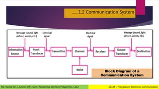
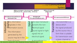
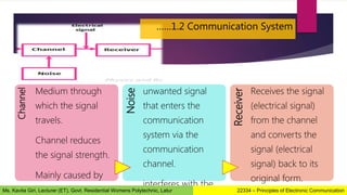
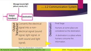
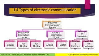
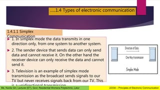
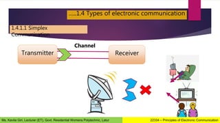
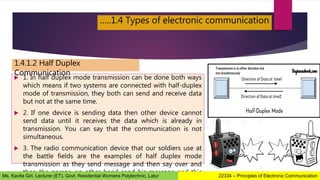
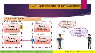
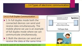
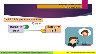
Chapter 1
BASICS OF ELECTRONICS
COMMUNICATION
12 MARKS
08 HOURS
Ms. Kavita Giri
Lecturer (ET)
Government Residential Womens
Polytechnic, Latur
Contents
1.1 The elements of basic electronic communication systems.
1.2 Electromagnetic spectrum – different bands and their applications.
1.3 Transmission modes – simplex, half duplex, full duplex
Synchronous and Asynchronous
1.4 Sources of Noise
1.5 Definition of noise figure and SNR.
22334 – Principles of Electronic Communication
Ms. Kavita Giri, Lecturer (ET), Govt. Residential Womens Polytechnic, Latur
Learning Outcomes
 After completion of this chapter you should be able to:
 Define different terms related to electronic communication.
 Describe the functioning of communication system.
 Identify the various bands in the EM spectrum.
 Identify the various forms of electronic communication.
 Classify different types of noise based on its source.
22334 – Principles of Electronic Communication
Ms. Kavita Giri, Lecturer (ET), Govt. Residential Womens Polytechnic, Latur
1.1 Introduction to electronic communication
 The word communication arises from the Latin word
“commūnicāre”, which means ‘to share’.
 Communication is the basic step for the exchange of information.
 For example, a baby in a cradle, communicates with a cry that she
needs her mother. A cow moos loudly when it is in danger. A
person communicates with the help of a language.
 Communication is the bridge to share.
22334 – Principles of Electronic Communication
Ms. Kavita Giri, Lecturer (ET), Govt. Residential Womens Polytechnic, Latur
 Communication can be defined as
the process of exchange of
information through means such as
words, actions, signs, etc., between
two or more individuals.
….1.1 Introduction to electronic
communication
22334 – Principles of Electronic Communication
Ms. Kavita Giri, Lecturer (ET), Govt. Residential Womens Polytechnic, Latur
 For any living being, while co-existing, there occurs the necessity of exchange
of some information.
 Whenever a need for exchange of information arises, some means of
communication should exist.
 While the means of communication, can be anything such as gestures, signs,
symbols, or a language, the need for communication is inevitable.
 Language and gestures play an important role in human communication,
while sounds and actions are important for animal communication.
 However, when some message has to be conveyed, a communication has to
be established.
1.1.2 Need for
communication
22334 – Principles of Electronic Communication
Ms. Kavita Giri, Lecturer (ET), Govt. Residential Womens Polytechnic, Latur
1.1.3 Elements of communication system
Sender
(Transmitter)
Channel Receiver
Person who sends
the message
Source of
information
Sends the message by
speaking, writing or by
doing gestures
Medium through which
message signal travels
channel could
be ‘air’
sender sends the message
signal (sound waves
containing message)
through the air medium
person who receives
the message
has no information
to share but
receives
all TV sets and radios are
receivers.
22334 – Principles of Electronic Communication
Ms. Kavita Giri, Lecturer (ET), Govt. Residential Womens Polytechnic, Latur
1.1.3 Elements of communication system
22334 – Principles of Electronic Communication
Ms. Kavita Giri, Lecturer (ET), Govt. Residential Womens Polytechnic, Latur
1.2 Communication System
 Communication means sending, receiving and processing of
information between two or more devices.
 Some examples of communication system include radio
broadcasting, television broadcasting, radio telegraphy, mobile
communication, computer communication etc.
A collection of elements (devices) which works together to
establish a communication between the sender and receiver is
called a communication system.
22334 – Principles of Electronic Communication
Ms. Kavita Giri, Lecturer (ET), Govt. Residential Womens Polytechnic, Latur
……1.2 Communication System
Block Diagram of a
Communication System
22334 – Principles of Electronic Communication
Ms. Kavita Giri, Lecturer (ET), Govt. Residential Womens Polytechnic, Latur
Information
Source
This information
originates in the
information source.
The information
generated by the
source may be in the
form of sound
Input
Transducer
The input transducer
converts the non-
electrical signal
(sound signal or light
signal) into an
electrical signal.
A microphone is a
Transmitter
The transmitter is a
device which
the signal produced
by the source into a
form that is suitable
for transmission over
a given channel or
……1.2 Communication
System
22334 – Principles of Electronic Communication
Ms. Kavita Giri, Lecturer (ET), Govt. Residential Womens Polytechnic, Latur
Channel
Medium through
which the signal
travels.
Channel reduces
the signal strength.
Mainly caused by
the addition of
Noise
unwanted signal
that enters the
communication
system via the
communication
channel.
interferes with the
Receiver
Receives the signal
(electrical signal)
from the channel
and converts the
signal (electrical
signal) back to its
original form.
……1.2 Communication System
22334 – Principles of Electronic Communication
Ms. Kavita Giri, Lecturer (ET), Govt. Residential Womens Polytechnic, Latur
Output
Transducer
Converts the electrical
signal into a non-
electrical signal (sound
signal, light signal, or
both sound and light
signal).
The loudspeaker converts
Destination
Final Stage
Humans at some place are
considered as the destination.
A destination is a place where
humans consume the
information.
……1.2 Communication System
22334 – Principles of Electronic Communication
Ms. Kavita Giri, Lecturer (ET), Govt. Residential Womens Polytechnic, Latur
1.3 The Electromagnetic spectrum
Radiation
• Whenever a high frequency current flows through a conductor,
the power measured on both the ends is not same.
• A part of the power is dissipated in the resistance of conductor
and a part of it escapes into the free space. This escaped part is
radiation.
Propagation
• This radiated power then propagates in the free space in the
form of electromagnetic waves (EM).
The process of signal travel from transmitter to receiver has been divided into two parts as:
22334 – Principles of Electronic Communication
Ms. Kavita Giri, Lecturer (ET), Govt. Residential Womens Polytechnic, Latur
1.3 The Electromagnetic spectrum
22334 – Principles of Electronic Communication
Ms. Kavita Giri, Lecturer (ET), Govt. Residential Womens Polytechnic, Latur
Radiation Propagation
…..1.3 The Electromagnetic spectrum
 Electromagnetic waves (or radio waves)
are nothing but oscillations which
propagate in free space.
 They travel at the speed of light.
 These waves consists of moving fields of
electric and magnetic forces, thus known
as electromagnetic (EM) waves.
 The frequency of EM signal ranges from
few Hz to several GHz.
This entire range of frequencies of
EM waves is called as
Electromagnetic Spectrum.
22334 – Principles of Electronic Communication
Ms. Kavita Giri, Lecturer (ET), Govt. Residential Womens Polytechnic, Latur
…..1.3 The Electromagnetic spectrum
22334 – Principles of Electronic Communication
Ms. Kavita Giri, Lecturer (ET), Govt. Residential Womens Polytechnic, Latur
…..1.3 The Electromagnetic spectrum
22334 – Principles of Electronic Communication
Ms. Kavita Giri, Lecturer (ET), Govt. Residential Womens Polytechnic, Latur
https://youtu.be/1JpwDaOHppA
…..1.3 The Electromagnetic spectrum
22334 – Principles of Electronic Communication
Ms. Kavita Giri, Lecturer (ET), Govt. Residential Womens Polytechnic, Latur
…..1.3 The Electromagnetic spectrum
Sr. No. Frequency Band Applications
01 300 Hz to 3KHz Voice or audio communication
(Used in telephone lines)
02 VLF – 3KHz to 30KHz Submarine, military, navy communication
03 LF – 30KHz to 300KHz Marine, Navigation, also used as subcarrier frequency
04 MF – 300KHz to 3MHz MW band of AM radio broadcast
05 HF- 3MHz to 30MHz SW i.e., short wave band of AM radio
06 VHF – 30MHz to 300MHz TV and FM radio broadcasting
07 UHF – 300MHz to 3GHz UHF TV channels, mobile phones
08 SHF – 3GHz to 30GHz Satellite and Radar
09 EHF – 30GHz to 300GHz Satellite and Radar
22334 – Principles of Electronic Communication
Ms. Kavita Giri, Lecturer (ET), Govt. Residential Womens Polytechnic, Latur
1.4 Types of electronic communication
Electronic
Communication
Systems
Direction of
Information
transfer
Simplex
Half
Duplex
Full
Duplex
Nature of
information
Signal
Analog Digital
Technique
of
transmissio
n
Baseban
d
transmiss
ion
Modulati
on
techniqu
e
22334 – Principles of Electronic Communication
Ms. Kavita Giri, Lecturer (ET), Govt. Residential Womens Polytechnic, Latur
 1. In simplex mode the data transmits in one
direction only, from one system to another system.
 2. The sender device that sends data can only send
data and cannot receive it. On the other hand the
receiver device can only receive the data and cannot
send it.
 3. Television is an example of simplex mode
transmission as the broadcast sends signals to our
TV but never receives signals back from our TV. This
is a unidirectional transmission.
…..1.4 Types of electronic communication
1.4.1.1 Simplex
Communication
22334 – Principles of Electronic Communication
Ms. Kavita Giri, Lecturer (ET), Govt. Residential Womens Polytechnic, Latur
…..1.4 Types of electronic communication
1.4.1.1 Simplex
Communication
Transmitter Receiver
Channel
22334 – Principles of Electronic Communication
Ms. Kavita Giri, Lecturer (ET), Govt. Residential Womens Polytechnic, Latur
 Advantages of Simplex Mode:
The full capacity of the transmission medium is utilized as the
transmission is one way and cannot have traffic issues.
 Disadvantages of Simplex Mode:
No bidirectional communication is possible. Two devices cannot
communicate with each other using simplex mode of transmission.
…..1.4 Types of electronic communication
1.4.1.1 Simplex
Communication
22334 – Principles of Electronic Communication
Ms. Kavita Giri, Lecturer (ET), Govt. Residential Womens Polytechnic, Latur
 1. In half duplex mode transmission can be done both ways
which means if two systems are connected with half-duplex
mode of transmission, they both can send and receive data
but not at the same time.
 2. If one device is sending data then other device cannot
send data until it receives the data which is already in
transmission. You can say that the communication is not
simultaneous.
 3. The radio communication device that our soldiers use at
the battle fields are the examples of half duplex mode
transmission as they send message and then say over and
then the person on other hand send his message and this
…..1.4 Types of electronic communication
1.4.1.2 Half Duplex
Communication
22334 – Principles of Electronic Communication
Ms. Kavita Giri, Lecturer (ET), Govt. Residential Womens Polytechnic, Latur
…..1.4 Types of electronic communication
1.4.1.2 Half Duplex
Communication
Trans-
Receiver1
Trans-
Receiver2
Alpha!!! There
is an
emergency…
Alpha come in…
Delta Over.
Delta!!!
Message
received. Just
reporting…
Alpha Over.
Trans-
Receiver1
Trans-
Receiver2
Transmits
Transmits
Receives
Receives
22334 – Principles of Electronic Communication
Ms. Kavita Giri, Lecturer (ET), Govt. Residential Womens Polytechnic, Latur
 Advantages of Half-Duplex mode:
Both devices can send and receive data.
Whole bandwidth can be utilized as at a time only one signal
transmits.
 Disadvantages of Half-Duplex mode:
The disadvantage in half duplex mode is that the other device
cannot send data until it receives the data which is already in
transmission, this can cause delays to the communication.
…..1.4 Types of electronic communication
1.4.1.2 Half Duplex
Communication
22334 – Principles of Electronic Communication
Ms. Kavita Giri, Lecturer (ET), Govt. Residential Womens Polytechnic, Latur
 1. In full duplex mode both the
connected devices can send and
receive data simultaneously. The
mobile phone we use is an example
of full duplex mode where we can
communicate simultaneously.
 2. Both the devices can send and
receive the data at the same time.
…..1.4 Types of electronic communication
1.4.1.3 Full Duplex Communication
22334 – Principles of Electronic Communication
Ms. Kavita Giri, Lecturer (ET), Govt. Residential Womens Polytechnic, Latur
…..1.4 Types of electronic
communication
1.4.1.3 Full Duplex Communication
Transceiv
er A
Transceiv
er B
Channel
22334 – Principles of Electronic Communication
Ms. Kavita Giri, Lecturer (ET), Govt. Residential Womens Polytechnic, Latur
 Advantages of Full Duplex mode:
No delays in communication as both can send and receive data
simultaneously.
 Disadvantages of Full Duplex mode:
No proper bandwidth utilization as the same line is used for sending and
receiving data at the same time.
…..1.4 Types of electronic communication
1.4.1.3 Full Duplex Communication
22334 – Principles of Electronic Communication
Ms. Kavita Giri, Lecturer (ET), Govt. Residential Womens Polytechnic, Latur
 An analog
communication system is a
communication system where
the information signal sent from
point A to point B can only be
described as an analog signal.
 An example of this is Monica
speaking to Carl over the
telephone.
…..1.4 Types of electronic communication
1.4.2.1 Analog Communication
System
Hello Carl…
How are you??
22334 – Principles of Electronic Communication
Ms. Kavita Giri, Lecturer (ET), Govt. Residential Womens Polytechnic, Latur
 A digital communication system is a
communication system where the information
signal sent from A to B can be fully described as a
digital signal.
 For example, Here, data is sent from one
computer to another over a wire. The computer at
point A is sending 0s or 1s to the computer at
point B;
 0 is being represented by −5 V for a duration of
time T and a 1 is being represented by a +5 V for
the same duration T.
…..1.4 Types of electronic communication
1.4.2.2 Digital Communication
A
B
22334 – Principles of Electronic Communication
Ms. Kavita Giri, Lecturer (ET), Govt. Residential Womens Polytechnic, Latur
…..1.4 Types of electronic communication
1.4.3.1 Baseband Transmission
 The input signal to a communication
system is either analog i.e., sound or
picture or digital i.e., computer data.
 Sound or picture is converted into
electrical signal.
 The electrical equivalent of the original
information signal is known as the
baseband signal.
 The communication system in which the
baseband signals are transmitted directly 22334 – Principles of Electronic Communication
Ms. Kavita Giri, Lecturer (ET), Govt. Residential Womens Polytechnic, Latur
1.5 Applications of
Communication
 AM and FM radio broadcasting
 TV broadcasting
 Telemetry
 Cable TV systems
 FAX, Pager,
 Telephones
 Mobile Phones
 Radar
22334 – Principles of Electronic Communication
Ms. Kavita Giri, Lecturer (ET), Govt. Residential Womens Polytechnic, Latur
1.8 Noise
 Noise is an unwanted signal which interferes
with the original message signal and corrupts
the parameters of the message signal.
 This alteration in the communication process,
leads to the message getting altered.
 It is most likely to be entered at the channel or
the receiver.
 It is quite random and unpredictable.
Measures are usually taken to reduce it,
though it can’t be completely eliminated.
 Most common examples of noise are −
• Hiss sound in radio receivers
• Buzz sound amidst of telephone
1.8.1 What is
Noise?
22334 – Principles of Electronic Communication
Ms. Kavita Giri, Lecturer (ET), Govt. Residential Womens Polytechnic, Latur
 Noise limits the operating range of the systems
Noise indirectly places a limit on the weakest signal that can be
amplified by an amplifier. The oscillator in the mixer circuit may limit its
frequency because of noise. A system’s operation depends on the
operation of its circuits. Noise limits the smallest signal that a receiver
capable of processing.
 Noise affects the sensitivity of receivers
Sensitivity is the minimum amount of input signal necessary to obtain
the specified quality output. Noise affects the sensitivity of a receiver
system, which eventually affects the output.
……1.8 Noise
1.8.2 Effects of
Noise
22334 – Principles of Electronic Communication
Ms. Kavita Giri, Lecturer (ET), Govt. Residential Womens Polytechnic, Latur
……1.8 Noise
1.8.3 Classification of
Noise
Noise
External
Atmosp
heric
noise
Extra-
terrestri
al noise
Industri
al
noise.
Internal
Therma
l
agitatio
n noise
Shot
noise
Transit-
time
noise
Miscella
neous
Noise
22334 – Principles of Electronic Communication
Ms. Kavita Giri, Lecturer (ET), Govt. Residential Womens Polytechnic, Latur
……1.8 Noise
1.8.3.1 External Noise
 This noise is produced by the external sources which may occur in
the medium or channel of communication, usually.
 This noise cannot be completely eliminated.
 The best way is to avoid the noise from affecting the signal.
 Types of external noise are −
1. Atmospheric noise
2. Extra-terrestrial noise
3. Industrial noise
22334 – Principles of Electronic Communication
Ms. Kavita Giri, Lecturer (ET), Govt. Residential Womens Polytechnic, Latur
……1.8 Noise
1.8.3.1 External Noise
1. Atmospheric Noise
 Atmospheric noise or static is caused by lighting
discharges in thunderstorms and other natural
electrical disturbances occurring in the atmosphere.
 These electrical impulses are random in nature. Hence
the energy is spread over the complete frequency
spectrum used for radio communication.
 Atmospheric noise accordingly consists of spurious
radio signals with components spread over a wide
frequency range.
 It is propagated over the earth in the same way as the
desired radio waves of the same frequencies, so that a
given receiving point, the receiving antenna picks up
not only the signal but also the static from all the
thunderstorms, local or remote. 22334 – Principles of Electronic Communication
Ms. Kavita Giri, Lecturer (ET), Govt. Residential Womens Polytechnic, Latur
……1.8 Noise
1.8.3.1 External Noise
2. Extra-terrestrial Noise
A) Solar Noise:
• This is the electrical noise emanating from the sun.
• Under quite conditions, there is a steady radiation of noise from the sun.
• This results because sun is a large body at a very high temperature (exceeding
6000°C on the surface), and radiates electrical energy in the form of noise over a
very wide frequency spectrum including the spectrum used for radio
communication.
• The intensity produced by the sun varies with time.
• In fact, the sun has a repeating 11-Year noise cycle.
• During the peak of the cycle, the sun produces some amount of noise that causes
tremendous radio signal interference, making many frequencies unusable for
22334 – Principles of Electronic Communication
Ms. Kavita Giri, Lecturer (ET), Govt. Residential Womens Polytechnic, Latur
……1.8 Noise
1.8.3.1 External Noise
2. Extra-terrestrial Noise
B) Cosmic Noise:
• Distant stars are also suns and have high temperatures.
• These stars, therefore, radiate noise in the same way as our sun.
• The noise received from these distant stars is thermal noise (or
black body noise) and is distributing almost uniformly over the
entire sky.
• We also receive noise from the center of our own galaxy (The
22334 – Principles of Electronic Communication
Ms. Kavita Giri, Lecturer (ET), Govt. Residential Womens Polytechnic, Latur
……1.8 Noise
1.8.3.1 External Noise
3. Industrial Noise
• It is the electrical noise produced by such sources
as automobiles and aircraft ignition, electrical
motors and switch gears, leakage from high
voltage lines, fluorescent lights, and numerous
other heavy electrical machines.
• Such noises are produced by the arc discharge
taking place during operation of these machines.
• Such man-made noise is most intensive in
industrial and densely populated areas.
• Man-made noise in such areas far exceeds all
other sources of noise in the frequency range
22334 – Principles of Electronic Communication
Ms. Kavita Giri, Lecturer (ET), Govt. Residential Womens Polytechnic, Latur
……1.8 Noise
1.8.3.2 Internal Noise
 This noise is produced by the receiver components while functioning.
 The components in the circuits, due to continuous functioning, may
produce few types of noise.
 This noise is quantifiable.
 A proper receiver design may lower the effect of this internal noise.
 Types of internal noise are −
1. Thermal Noise
2. Shot Noise
3. Transit time Noise
4. Miscellaneous Noise
22334 – Principles of Electronic Communication
Ms. Kavita Giri, Lecturer (ET), Govt. Residential Womens Polytechnic, Latur
……1.8 Noise
1.8.3.2 Internal Noise
1. Thermal Noise (Johnson noise or White noise)
• Conductors contain a large number of free electrons and ions strongly bound by
molecular forces.
• The ions vibrate randomly about their normal (average) positions, however, this
vibration being a function of the temperature.
• Continuous collisions between the electrons and the vibrating ions take place.
• Thus there is a continuous transfer of energy between the ions and electrons.
• This is the source of resistance in a conductor.
• The movement of free electrons constitutes a current which is purely random in
nature and over a long time averages zero.
• There is a random motion of the electrons which give rise to noise voltage called
thermal noise. 22334 – Principles of Electronic Communication
Ms. Kavita Giri, Lecturer (ET), Govt. Residential Womens Polytechnic, Latur
……1.8 Noise
1.8.3.2 Internal Noise
2. Shot Noise
 Shot noise is produced by the random movement of electrons
or holes across a PN junction.
 Even through current flow is established by external bias
voltages, there will still be some random movement of
electrons or holes due to discontinuities in the device.
 An example of such a discontinuity is the contact between the
copper lead and the semiconductor materials.
 The interface between the two creates a discontinuity that
causes random movement of the current carriers.
22334 – Principles of Electronic Communication
Ms. Kavita Giri, Lecturer (ET), Govt. Residential Womens Polytechnic, Latur
……1.8 Noise
1.8.3.2 Internal Noise
3. Transit time Noise
 Transit time is the duration of time that it takes for a current carrier
such as a hole or current to move from the input to the output.
 The devices themselves are very tiny, so the distances involved are
minimal.
 Yet the time it takes for the current carriers to move even a short
distance is finite.
 At low frequencies this time is negligible. But when the frequency of
operation is high and the signal being processed is the magnitude as
the transit time, then problem can occur. 22334 – Principles of Electronic Communication
Ms. Kavita Giri, Lecturer (ET), Govt. Residential Womens Polytechnic, Latur
……1.8 Noise
1.8.3.2 Internal Noise 4. Miscellaneous
Noise
Flicker noise or modulation noise
It is the one appearing in transistors
operating at low audio frequencies.
Flicker noise is proportional to the
emitter current and junction
temperature.
However, this noise is inversely
proportional to the frequency. Hence
it may be neglected at frequencies
above about 500 Hz and it, Therefore,
Partition noise
It occurs whenever current has to
divide between two or more paths,
and results from the random
fluctuations in the division.
It would be expected, therefore, that
a diode would be less noisy than a
transistor (all other factors being
equal) If the third electrode draws
current (i.e.., the base current).
It is for this reason that the inputs of
22334 – Principles of Electronic Communication
Ms. Kavita Giri, Lecturer (ET), Govt. Residential Womens Polytechnic, Latur
1.9 Signal to Noise Ratio & Noise Figure
 Signal to Noise Ratio
 Signal-to-Noise Ratio (SNR) is
the ratio of the signal power
to the noise power.
 The higher the value of SNR,
the greater will be the quality
of the received output.
 Noise Figure
 The ratio of output SNR to the
input SNR can be termed as
the Noise Figure.
 It is denoted by F.
 It describes the performance of
a device.
22334 – Principles of Electronic Communication
Ms. Kavita Giri, Lecturer (ET), Govt. Residential Womens Polytechnic, Latur
Basics of Electronic Communication

Basics of Electronic Communication

  • 1.
    Chapter 1 BASICS OFELECTRONICS COMMUNICATION 12 MARKS 08 HOURS Ms. Kavita Giri Lecturer (ET) Government Residential Womens Polytechnic, Latur
  • 2.
    Contents 1.1 The elementsof basic electronic communication systems. 1.2 Electromagnetic spectrum – different bands and their applications. 1.3 Transmission modes – simplex, half duplex, full duplex Synchronous and Asynchronous 1.4 Sources of Noise 1.5 Definition of noise figure and SNR. 22334 – Principles of Electronic Communication Ms. Kavita Giri, Lecturer (ET), Govt. Residential Womens Polytechnic, Latur
  • 3.
    Learning Outcomes  Aftercompletion of this chapter you should be able to:  Define different terms related to electronic communication.  Describe the functioning of communication system.  Identify the various bands in the EM spectrum.  Identify the various forms of electronic communication.  Classify different types of noise based on its source. 22334 – Principles of Electronic Communication Ms. Kavita Giri, Lecturer (ET), Govt. Residential Womens Polytechnic, Latur
  • 4.
    1.1 Introduction toelectronic communication  The word communication arises from the Latin word “commūnicāre”, which means ‘to share’.  Communication is the basic step for the exchange of information.  For example, a baby in a cradle, communicates with a cry that she needs her mother. A cow moos loudly when it is in danger. A person communicates with the help of a language.  Communication is the bridge to share. 22334 – Principles of Electronic Communication Ms. Kavita Giri, Lecturer (ET), Govt. Residential Womens Polytechnic, Latur
  • 5.
     Communication canbe defined as the process of exchange of information through means such as words, actions, signs, etc., between two or more individuals. ….1.1 Introduction to electronic communication 22334 – Principles of Electronic Communication Ms. Kavita Giri, Lecturer (ET), Govt. Residential Womens Polytechnic, Latur
  • 7.
     For anyliving being, while co-existing, there occurs the necessity of exchange of some information.  Whenever a need for exchange of information arises, some means of communication should exist.  While the means of communication, can be anything such as gestures, signs, symbols, or a language, the need for communication is inevitable.  Language and gestures play an important role in human communication, while sounds and actions are important for animal communication.  However, when some message has to be conveyed, a communication has to be established. 1.1.2 Need for communication 22334 – Principles of Electronic Communication Ms. Kavita Giri, Lecturer (ET), Govt. Residential Womens Polytechnic, Latur
  • 8.
    1.1.3 Elements ofcommunication system Sender (Transmitter) Channel Receiver Person who sends the message Source of information Sends the message by speaking, writing or by doing gestures Medium through which message signal travels channel could be ‘air’ sender sends the message signal (sound waves containing message) through the air medium person who receives the message has no information to share but receives all TV sets and radios are receivers. 22334 – Principles of Electronic Communication Ms. Kavita Giri, Lecturer (ET), Govt. Residential Womens Polytechnic, Latur
  • 9.
    1.1.3 Elements ofcommunication system 22334 – Principles of Electronic Communication Ms. Kavita Giri, Lecturer (ET), Govt. Residential Womens Polytechnic, Latur
  • 10.
    1.2 Communication System Communication means sending, receiving and processing of information between two or more devices.  Some examples of communication system include radio broadcasting, television broadcasting, radio telegraphy, mobile communication, computer communication etc. A collection of elements (devices) which works together to establish a communication between the sender and receiver is called a communication system. 22334 – Principles of Electronic Communication Ms. Kavita Giri, Lecturer (ET), Govt. Residential Womens Polytechnic, Latur
  • 11.
    ……1.2 Communication System BlockDiagram of a Communication System 22334 – Principles of Electronic Communication Ms. Kavita Giri, Lecturer (ET), Govt. Residential Womens Polytechnic, Latur
  • 12.
    Information Source This information originates inthe information source. The information generated by the source may be in the form of sound Input Transducer The input transducer converts the non- electrical signal (sound signal or light signal) into an electrical signal. A microphone is a Transmitter The transmitter is a device which the signal produced by the source into a form that is suitable for transmission over a given channel or ……1.2 Communication System 22334 – Principles of Electronic Communication Ms. Kavita Giri, Lecturer (ET), Govt. Residential Womens Polytechnic, Latur
  • 13.
    Channel Medium through which thesignal travels. Channel reduces the signal strength. Mainly caused by the addition of Noise unwanted signal that enters the communication system via the communication channel. interferes with the Receiver Receives the signal (electrical signal) from the channel and converts the signal (electrical signal) back to its original form. ……1.2 Communication System 22334 – Principles of Electronic Communication Ms. Kavita Giri, Lecturer (ET), Govt. Residential Womens Polytechnic, Latur
  • 14.
    Output Transducer Converts the electrical signalinto a non- electrical signal (sound signal, light signal, or both sound and light signal). The loudspeaker converts Destination Final Stage Humans at some place are considered as the destination. A destination is a place where humans consume the information. ……1.2 Communication System 22334 – Principles of Electronic Communication Ms. Kavita Giri, Lecturer (ET), Govt. Residential Womens Polytechnic, Latur
  • 15.
    1.3 The Electromagneticspectrum Radiation • Whenever a high frequency current flows through a conductor, the power measured on both the ends is not same. • A part of the power is dissipated in the resistance of conductor and a part of it escapes into the free space. This escaped part is radiation. Propagation • This radiated power then propagates in the free space in the form of electromagnetic waves (EM). The process of signal travel from transmitter to receiver has been divided into two parts as: 22334 – Principles of Electronic Communication Ms. Kavita Giri, Lecturer (ET), Govt. Residential Womens Polytechnic, Latur
  • 16.
    1.3 The Electromagneticspectrum 22334 – Principles of Electronic Communication Ms. Kavita Giri, Lecturer (ET), Govt. Residential Womens Polytechnic, Latur Radiation Propagation
  • 17.
    …..1.3 The Electromagneticspectrum  Electromagnetic waves (or radio waves) are nothing but oscillations which propagate in free space.  They travel at the speed of light.  These waves consists of moving fields of electric and magnetic forces, thus known as electromagnetic (EM) waves.  The frequency of EM signal ranges from few Hz to several GHz. This entire range of frequencies of EM waves is called as Electromagnetic Spectrum. 22334 – Principles of Electronic Communication Ms. Kavita Giri, Lecturer (ET), Govt. Residential Womens Polytechnic, Latur
  • 18.
    …..1.3 The Electromagneticspectrum 22334 – Principles of Electronic Communication Ms. Kavita Giri, Lecturer (ET), Govt. Residential Womens Polytechnic, Latur
  • 19.
    …..1.3 The Electromagneticspectrum 22334 – Principles of Electronic Communication Ms. Kavita Giri, Lecturer (ET), Govt. Residential Womens Polytechnic, Latur https://youtu.be/1JpwDaOHppA
  • 20.
    …..1.3 The Electromagneticspectrum 22334 – Principles of Electronic Communication Ms. Kavita Giri, Lecturer (ET), Govt. Residential Womens Polytechnic, Latur
  • 21.
    …..1.3 The Electromagneticspectrum Sr. No. Frequency Band Applications 01 300 Hz to 3KHz Voice or audio communication (Used in telephone lines) 02 VLF – 3KHz to 30KHz Submarine, military, navy communication 03 LF – 30KHz to 300KHz Marine, Navigation, also used as subcarrier frequency 04 MF – 300KHz to 3MHz MW band of AM radio broadcast 05 HF- 3MHz to 30MHz SW i.e., short wave band of AM radio 06 VHF – 30MHz to 300MHz TV and FM radio broadcasting 07 UHF – 300MHz to 3GHz UHF TV channels, mobile phones 08 SHF – 3GHz to 30GHz Satellite and Radar 09 EHF – 30GHz to 300GHz Satellite and Radar 22334 – Principles of Electronic Communication Ms. Kavita Giri, Lecturer (ET), Govt. Residential Womens Polytechnic, Latur
  • 22.
    1.4 Types ofelectronic communication Electronic Communication Systems Direction of Information transfer Simplex Half Duplex Full Duplex Nature of information Signal Analog Digital Technique of transmissio n Baseban d transmiss ion Modulati on techniqu e 22334 – Principles of Electronic Communication Ms. Kavita Giri, Lecturer (ET), Govt. Residential Womens Polytechnic, Latur
  • 23.
     1. Insimplex mode the data transmits in one direction only, from one system to another system.  2. The sender device that sends data can only send data and cannot receive it. On the other hand the receiver device can only receive the data and cannot send it.  3. Television is an example of simplex mode transmission as the broadcast sends signals to our TV but never receives signals back from our TV. This is a unidirectional transmission. …..1.4 Types of electronic communication 1.4.1.1 Simplex Communication 22334 – Principles of Electronic Communication Ms. Kavita Giri, Lecturer (ET), Govt. Residential Womens Polytechnic, Latur
  • 24.
    …..1.4 Types ofelectronic communication 1.4.1.1 Simplex Communication Transmitter Receiver Channel 22334 – Principles of Electronic Communication Ms. Kavita Giri, Lecturer (ET), Govt. Residential Womens Polytechnic, Latur
  • 25.
     Advantages ofSimplex Mode: The full capacity of the transmission medium is utilized as the transmission is one way and cannot have traffic issues.  Disadvantages of Simplex Mode: No bidirectional communication is possible. Two devices cannot communicate with each other using simplex mode of transmission. …..1.4 Types of electronic communication 1.4.1.1 Simplex Communication 22334 – Principles of Electronic Communication Ms. Kavita Giri, Lecturer (ET), Govt. Residential Womens Polytechnic, Latur
  • 26.
     1. Inhalf duplex mode transmission can be done both ways which means if two systems are connected with half-duplex mode of transmission, they both can send and receive data but not at the same time.  2. If one device is sending data then other device cannot send data until it receives the data which is already in transmission. You can say that the communication is not simultaneous.  3. The radio communication device that our soldiers use at the battle fields are the examples of half duplex mode transmission as they send message and then say over and then the person on other hand send his message and this …..1.4 Types of electronic communication 1.4.1.2 Half Duplex Communication 22334 – Principles of Electronic Communication Ms. Kavita Giri, Lecturer (ET), Govt. Residential Womens Polytechnic, Latur
  • 27.
    …..1.4 Types ofelectronic communication 1.4.1.2 Half Duplex Communication Trans- Receiver1 Trans- Receiver2 Alpha!!! There is an emergency… Alpha come in… Delta Over. Delta!!! Message received. Just reporting… Alpha Over. Trans- Receiver1 Trans- Receiver2 Transmits Transmits Receives Receives 22334 – Principles of Electronic Communication Ms. Kavita Giri, Lecturer (ET), Govt. Residential Womens Polytechnic, Latur
  • 28.
     Advantages ofHalf-Duplex mode: Both devices can send and receive data. Whole bandwidth can be utilized as at a time only one signal transmits.  Disadvantages of Half-Duplex mode: The disadvantage in half duplex mode is that the other device cannot send data until it receives the data which is already in transmission, this can cause delays to the communication. …..1.4 Types of electronic communication 1.4.1.2 Half Duplex Communication 22334 – Principles of Electronic Communication Ms. Kavita Giri, Lecturer (ET), Govt. Residential Womens Polytechnic, Latur
  • 29.
     1. Infull duplex mode both the connected devices can send and receive data simultaneously. The mobile phone we use is an example of full duplex mode where we can communicate simultaneously.  2. Both the devices can send and receive the data at the same time. …..1.4 Types of electronic communication 1.4.1.3 Full Duplex Communication 22334 – Principles of Electronic Communication Ms. Kavita Giri, Lecturer (ET), Govt. Residential Womens Polytechnic, Latur
  • 30.
    …..1.4 Types ofelectronic communication 1.4.1.3 Full Duplex Communication Transceiv er A Transceiv er B Channel 22334 – Principles of Electronic Communication Ms. Kavita Giri, Lecturer (ET), Govt. Residential Womens Polytechnic, Latur
  • 31.
     Advantages ofFull Duplex mode: No delays in communication as both can send and receive data simultaneously.  Disadvantages of Full Duplex mode: No proper bandwidth utilization as the same line is used for sending and receiving data at the same time. …..1.4 Types of electronic communication 1.4.1.3 Full Duplex Communication 22334 – Principles of Electronic Communication Ms. Kavita Giri, Lecturer (ET), Govt. Residential Womens Polytechnic, Latur
  • 32.
     An analog communicationsystem is a communication system where the information signal sent from point A to point B can only be described as an analog signal.  An example of this is Monica speaking to Carl over the telephone. …..1.4 Types of electronic communication 1.4.2.1 Analog Communication System Hello Carl… How are you?? 22334 – Principles of Electronic Communication Ms. Kavita Giri, Lecturer (ET), Govt. Residential Womens Polytechnic, Latur
  • 33.
     A digitalcommunication system is a communication system where the information signal sent from A to B can be fully described as a digital signal.  For example, Here, data is sent from one computer to another over a wire. The computer at point A is sending 0s or 1s to the computer at point B;  0 is being represented by −5 V for a duration of time T and a 1 is being represented by a +5 V for the same duration T. …..1.4 Types of electronic communication 1.4.2.2 Digital Communication A B 22334 – Principles of Electronic Communication Ms. Kavita Giri, Lecturer (ET), Govt. Residential Womens Polytechnic, Latur
  • 34.
    …..1.4 Types ofelectronic communication 1.4.3.1 Baseband Transmission  The input signal to a communication system is either analog i.e., sound or picture or digital i.e., computer data.  Sound or picture is converted into electrical signal.  The electrical equivalent of the original information signal is known as the baseband signal.  The communication system in which the baseband signals are transmitted directly 22334 – Principles of Electronic Communication Ms. Kavita Giri, Lecturer (ET), Govt. Residential Womens Polytechnic, Latur
  • 35.
    1.5 Applications of Communication AM and FM radio broadcasting  TV broadcasting  Telemetry  Cable TV systems  FAX, Pager,  Telephones  Mobile Phones  Radar 22334 – Principles of Electronic Communication Ms. Kavita Giri, Lecturer (ET), Govt. Residential Womens Polytechnic, Latur
  • 36.
    1.8 Noise  Noiseis an unwanted signal which interferes with the original message signal and corrupts the parameters of the message signal.  This alteration in the communication process, leads to the message getting altered.  It is most likely to be entered at the channel or the receiver.  It is quite random and unpredictable. Measures are usually taken to reduce it, though it can’t be completely eliminated.  Most common examples of noise are − • Hiss sound in radio receivers • Buzz sound amidst of telephone 1.8.1 What is Noise? 22334 – Principles of Electronic Communication Ms. Kavita Giri, Lecturer (ET), Govt. Residential Womens Polytechnic, Latur
  • 37.
     Noise limitsthe operating range of the systems Noise indirectly places a limit on the weakest signal that can be amplified by an amplifier. The oscillator in the mixer circuit may limit its frequency because of noise. A system’s operation depends on the operation of its circuits. Noise limits the smallest signal that a receiver capable of processing.  Noise affects the sensitivity of receivers Sensitivity is the minimum amount of input signal necessary to obtain the specified quality output. Noise affects the sensitivity of a receiver system, which eventually affects the output. ……1.8 Noise 1.8.2 Effects of Noise 22334 – Principles of Electronic Communication Ms. Kavita Giri, Lecturer (ET), Govt. Residential Womens Polytechnic, Latur
  • 38.
    ……1.8 Noise 1.8.3 Classificationof Noise Noise External Atmosp heric noise Extra- terrestri al noise Industri al noise. Internal Therma l agitatio n noise Shot noise Transit- time noise Miscella neous Noise 22334 – Principles of Electronic Communication Ms. Kavita Giri, Lecturer (ET), Govt. Residential Womens Polytechnic, Latur
  • 39.
    ……1.8 Noise 1.8.3.1 ExternalNoise  This noise is produced by the external sources which may occur in the medium or channel of communication, usually.  This noise cannot be completely eliminated.  The best way is to avoid the noise from affecting the signal.  Types of external noise are − 1. Atmospheric noise 2. Extra-terrestrial noise 3. Industrial noise 22334 – Principles of Electronic Communication Ms. Kavita Giri, Lecturer (ET), Govt. Residential Womens Polytechnic, Latur
  • 40.
    ……1.8 Noise 1.8.3.1 ExternalNoise 1. Atmospheric Noise  Atmospheric noise or static is caused by lighting discharges in thunderstorms and other natural electrical disturbances occurring in the atmosphere.  These electrical impulses are random in nature. Hence the energy is spread over the complete frequency spectrum used for radio communication.  Atmospheric noise accordingly consists of spurious radio signals with components spread over a wide frequency range.  It is propagated over the earth in the same way as the desired radio waves of the same frequencies, so that a given receiving point, the receiving antenna picks up not only the signal but also the static from all the thunderstorms, local or remote. 22334 – Principles of Electronic Communication Ms. Kavita Giri, Lecturer (ET), Govt. Residential Womens Polytechnic, Latur
  • 41.
    ……1.8 Noise 1.8.3.1 ExternalNoise 2. Extra-terrestrial Noise A) Solar Noise: • This is the electrical noise emanating from the sun. • Under quite conditions, there is a steady radiation of noise from the sun. • This results because sun is a large body at a very high temperature (exceeding 6000°C on the surface), and radiates electrical energy in the form of noise over a very wide frequency spectrum including the spectrum used for radio communication. • The intensity produced by the sun varies with time. • In fact, the sun has a repeating 11-Year noise cycle. • During the peak of the cycle, the sun produces some amount of noise that causes tremendous radio signal interference, making many frequencies unusable for 22334 – Principles of Electronic Communication Ms. Kavita Giri, Lecturer (ET), Govt. Residential Womens Polytechnic, Latur
  • 42.
    ……1.8 Noise 1.8.3.1 ExternalNoise 2. Extra-terrestrial Noise B) Cosmic Noise: • Distant stars are also suns and have high temperatures. • These stars, therefore, radiate noise in the same way as our sun. • The noise received from these distant stars is thermal noise (or black body noise) and is distributing almost uniformly over the entire sky. • We also receive noise from the center of our own galaxy (The 22334 – Principles of Electronic Communication Ms. Kavita Giri, Lecturer (ET), Govt. Residential Womens Polytechnic, Latur
  • 43.
    ……1.8 Noise 1.8.3.1 ExternalNoise 3. Industrial Noise • It is the electrical noise produced by such sources as automobiles and aircraft ignition, electrical motors and switch gears, leakage from high voltage lines, fluorescent lights, and numerous other heavy electrical machines. • Such noises are produced by the arc discharge taking place during operation of these machines. • Such man-made noise is most intensive in industrial and densely populated areas. • Man-made noise in such areas far exceeds all other sources of noise in the frequency range 22334 – Principles of Electronic Communication Ms. Kavita Giri, Lecturer (ET), Govt. Residential Womens Polytechnic, Latur
  • 44.
    ……1.8 Noise 1.8.3.2 InternalNoise  This noise is produced by the receiver components while functioning.  The components in the circuits, due to continuous functioning, may produce few types of noise.  This noise is quantifiable.  A proper receiver design may lower the effect of this internal noise.  Types of internal noise are − 1. Thermal Noise 2. Shot Noise 3. Transit time Noise 4. Miscellaneous Noise 22334 – Principles of Electronic Communication Ms. Kavita Giri, Lecturer (ET), Govt. Residential Womens Polytechnic, Latur
  • 45.
    ……1.8 Noise 1.8.3.2 InternalNoise 1. Thermal Noise (Johnson noise or White noise) • Conductors contain a large number of free electrons and ions strongly bound by molecular forces. • The ions vibrate randomly about their normal (average) positions, however, this vibration being a function of the temperature. • Continuous collisions between the electrons and the vibrating ions take place. • Thus there is a continuous transfer of energy between the ions and electrons. • This is the source of resistance in a conductor. • The movement of free electrons constitutes a current which is purely random in nature and over a long time averages zero. • There is a random motion of the electrons which give rise to noise voltage called thermal noise. 22334 – Principles of Electronic Communication Ms. Kavita Giri, Lecturer (ET), Govt. Residential Womens Polytechnic, Latur
  • 46.
    ……1.8 Noise 1.8.3.2 InternalNoise 2. Shot Noise  Shot noise is produced by the random movement of electrons or holes across a PN junction.  Even through current flow is established by external bias voltages, there will still be some random movement of electrons or holes due to discontinuities in the device.  An example of such a discontinuity is the contact between the copper lead and the semiconductor materials.  The interface between the two creates a discontinuity that causes random movement of the current carriers. 22334 – Principles of Electronic Communication Ms. Kavita Giri, Lecturer (ET), Govt. Residential Womens Polytechnic, Latur
  • 47.
    ……1.8 Noise 1.8.3.2 InternalNoise 3. Transit time Noise  Transit time is the duration of time that it takes for a current carrier such as a hole or current to move from the input to the output.  The devices themselves are very tiny, so the distances involved are minimal.  Yet the time it takes for the current carriers to move even a short distance is finite.  At low frequencies this time is negligible. But when the frequency of operation is high and the signal being processed is the magnitude as the transit time, then problem can occur. 22334 – Principles of Electronic Communication Ms. Kavita Giri, Lecturer (ET), Govt. Residential Womens Polytechnic, Latur
  • 48.
    ……1.8 Noise 1.8.3.2 InternalNoise 4. Miscellaneous Noise Flicker noise or modulation noise It is the one appearing in transistors operating at low audio frequencies. Flicker noise is proportional to the emitter current and junction temperature. However, this noise is inversely proportional to the frequency. Hence it may be neglected at frequencies above about 500 Hz and it, Therefore, Partition noise It occurs whenever current has to divide between two or more paths, and results from the random fluctuations in the division. It would be expected, therefore, that a diode would be less noisy than a transistor (all other factors being equal) If the third electrode draws current (i.e.., the base current). It is for this reason that the inputs of 22334 – Principles of Electronic Communication Ms. Kavita Giri, Lecturer (ET), Govt. Residential Womens Polytechnic, Latur
  • 49.
    1.9 Signal toNoise Ratio & Noise Figure  Signal to Noise Ratio  Signal-to-Noise Ratio (SNR) is the ratio of the signal power to the noise power.  The higher the value of SNR, the greater will be the quality of the received output.  Noise Figure  The ratio of output SNR to the input SNR can be termed as the Noise Figure.  It is denoted by F.  It describes the performance of a device. 22334 – Principles of Electronic Communication Ms. Kavita Giri, Lecturer (ET), Govt. Residential Womens Polytechnic, Latur