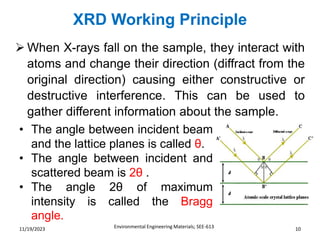
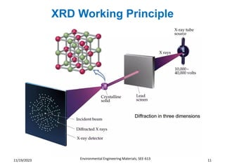
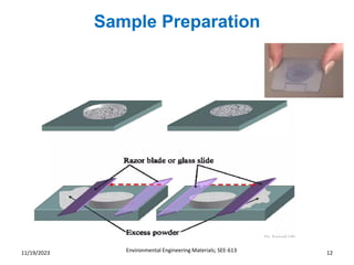
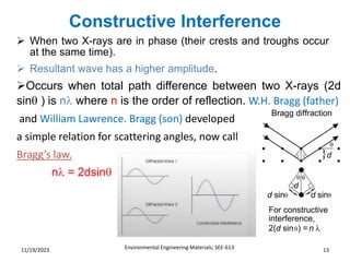
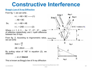
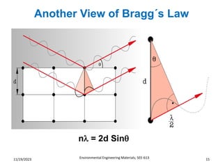
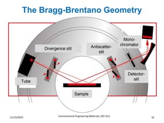
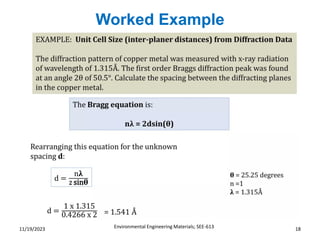
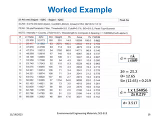
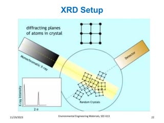
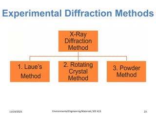
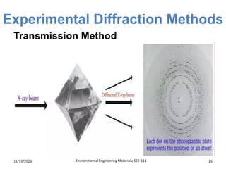
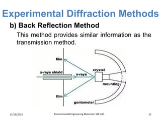
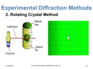
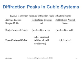
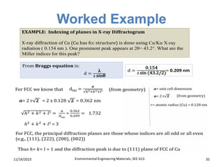
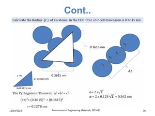
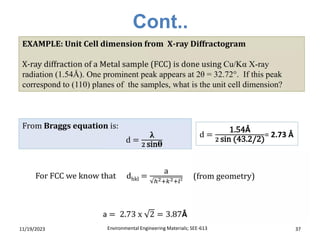
Top Rated Pune Call Girls Budhwar Peth ⟟ 6297143586 ⟟ Call Me For Genuine Se...
X-ray Diffraction (XRD) Technique Presentation
1. Undergraduate Course
Environmental Engineering Materials
(SEE-613) Theory
Course Instructor:
Engr. Shahbaz Hussain
Department of Structures and Environmental Engineering
University of Agriculture, Faisalabad-Pakistan
3. Contents
Environmental Engineering Materials; SEE-613 3
11/19/2023
❖ Introduction
❖ Background
❖ Why to select XRD?
❖ Production of X-rays
❖ Crystallography
❖ XRD Working Principle
❖ Sample Preparation
❖ Constructive Interference
❖ Bragg´s Law
❖ The Bragg-Brentano
Geometry
❖ X-ray Diffraction Animation
❖ Worked Example
❖ Fraunhofer diffraction
❖ Destructive Interference
❖ XRD Setup
❖ Experimental Diffraction Methods
❖ The Seven Crystal Systems
❖ Diffraction Peaks in Cubic
Systems
❖ Information obtained/derived from
XRD
❖ Applications of XRD Methods
4. Introduction
Environmental Engineering Materials; SEE-613 4
11/19/2023
• It is a novel & non-destructive method of chemical analysis, and a
variety of x-ray techniques are available in practice. These are
➢X-ray absorption
➢X-ray diffraction
➢X-ray fluorescence
• “Every crystalline substance gives a pattern; the same substance
always gives the same pattern; and in a mixture of substances each
produces its pattern independently of the others“.
• The X-ray diffraction pattern of a pure substance is, therefore, like a
"fingerprint of the substance". It is based on the scattering of X-rays by
crystals.
• When X-rays interact with a solid material, the scattered beams
causes diffraction.
Definition: The atomic planes of a crystal cause an incident beam of X-
rays to interfere with one another as they leave the crystal. The
phenomenon is called X-ray diffraction.
5. Introduction
Environmental Engineering Materials; SEE-613 5
11/19/2023
• X-rays are electro-magnetic
radiation with wavelengths in
the range 0.1 to 100 A0.
• X-rays used in diffraction
experiments have typical
wavelengths of 0.5 to 1.8 A0.
What is XRD?
6. Background
Environmental Engineering Materials; SEE-613 6
11/19/2023
• X- rays were discovered by Wilhelm
Conrad Roentgen in 1895 who
called them "X-rays" and it is also
called as "Roentgen Rays". In 1901,
he was honored by the Noble prize
for physics. In 1995 the German
Post edited a stamp, dedicated to
W.C. Röntgen.
• Gordon Darwin, grandson of C.
Robert Darwin developed 1912
dynamic theory of scattering of X-
rays at crystal lattice
• X- ray diffraction was discovered by
Max Von Laue in 1912.
Wilhelm Conrad Roentgen
Post Stamp
Gordon Darwin Max Von Laue
7. Why to select XRD?
Environmental Engineering Materials; SEE-613 7
11/19/2023
➢ Measure the average spacing's between layers of
atoms.
➢ Determine the orientation of a single crystal.
➢ Find the crystal structure of an unknown material.
➢ Measure the size, shape and internal stress of
small crystalline regions.
8. Production of X-rays
Environmental Engineering Materials; SEE-613 8
11/19/2023
Cross section of sealed-off filament X-ray tube
➢ X-rays are produced whenever high-speed electrons collide with a
metal target.
➢ A source of electrons — hot Tungsten (W) filament, a high
accelerating voltage between the cathode (W) and the anode and a
metal target, Cu, Al, MO, Mg.
➢ The anode is a water-cooled block of Cu containing desired target
metal.
9. Crystallography
Environmental Engineering Materials; SEE-613 9
11/19/2023
Crystalline materials are characterized by the orderly
periodic arrangements of atoms.
➢ The unit cell is the basic repeating unit that defines a
crystal.
➢Parallel planes of atoms intersecting the unit cell are used to
define directions and distances in the crystal.
➢These crystallographic planes are identified by Miller indices.
➢Miller indices are reflections of X-ray diffraction from the
planes of crystals and are represented by (hkl) values.
Determining the Miller indices (hkl) for the diffraction lines:
𝑑(ℎ𝑘𝑙) =
𝑎
ℎ2+ 𝑘2+ 𝑙2
10. XRD Working Principle
Environmental Engineering Materials; SEE-613 10
11/19/2023
➢ When X-rays fall on the sample, they interact with
atoms and change their direction (diffract from the
original direction) causing either constructive or
destructive interference. This can be used to
gather different information about the sample.
• The angle between incident beam
and the lattice planes is called θ.
• The angle between incident and
scattered beam is 2θ .
• The angle 2θ of maximum
intensity is called the Bragg
angle.
13. Constructive Interference
Environmental Engineering Materials; SEE-613 13
11/19/2023
➢ When two X-rays are in phase (their crests and troughs occur
at the same time).
➢ Resultant wave has a higher amplitude.
➢Occurs when total path difference between two X-rays (2d
sin ) is n where n is the order of reflection. W.H. Bragg (father)
and William Lawrence. Bragg (son) developed
a simple relation for scattering angles, now call
Bragg’s law.
n = 2dsin
14. Constructive Interference
Bragg's Law of X-ray Diffraction
From fig. 1, we can write .
n = AB + BC -------(1)
AB = BC
So, n = AB + AB
n = 2AB ------------(2)
Where, n = 1, 2, 3 ,… for 1st , 2nd , 3rd ….order
of reflection respectively. and =path difference
between two X-rays.
From fig. 2, According to trigonometric ratios,
we can write
Sin =
AB
d
AB = dSin ………(3)
By putting value of “AB” in equation (2), we
obtained:
n = 2dsin
This is known as Bragg's law of X-ray diffraction
11/19/2023
Environmental Engineering Materials; SEE-
613
14
Atomic Plane
Ray 1
Ray 2
Fig 1
Fig 2
15. Another View of Bragg´s Law
Environmental Engineering Materials; SEE-613 15
11/19/2023
n = 2d Sin
21. Destructive Interference
Environmental Engineering Materials; SEE-613 21
11/19/2023
• When two X-rays are out of phase (their crests
and troughs do not occur at the same time).
• Amplitude of resultant wave will be less than
incident waves.
• Occurs when total path
difference between two X-
rays (2d sin) is not equal to
n where n is the order of
reflection. Destructive Interference:
n 2d sin
24. Experimental Diffraction Methods
11/19/2023 Environmental Engineering Materials; SEE-613 24
1. LAUE'S METHOD
• In this method a single crystal is held stationary in the
path of radiation of continuous wavelength. While is
kept constant, the wavelength , is varied.
• A plane film receives the diffracted beams. A
developed film after its exposure shows a diffraction
pattern that consists of series of spots.
25. Experimental Diffraction Methods
11/19/2023 Environmental Engineering Materials; SEE-613 25
Laue’s method is divided into two types:
a) Transmission Method
b) Black Reflection Method
a) Transmission Method
A beam of x-ray is passed through the crystal, after
passing through the crystal, x-rays are diffracted and
recorded on a photographic plate.
27. Experimental Diffraction Methods
11/19/2023 Environmental Engineering Materials; SEE-613 27
b) Back Reflection Method
This method provides similar information as the
transmission method.
29. Experimental Diffraction Methods
11/19/2023 Environmental Engineering Materials; SEE-613 29
2. Rotating Crystal Method
In this method , a single crystal is rotated about
the fixed axis in a beam of monochromatic. The
angle is variable while the wavelength is kept
constant.
The variation of angle due to rotation of the
crystal brings different atomic planes in the
crystal into position.
To record such reflections a film is mounted on
a cylindrical holder that is concentric with a
rotating spindle.
30. Experimental Diffraction Methods
11/19/2023 Environmental Engineering Materials; SEE-613 30
2. Powder Method
• This method is useful for samples that are
difficult to obtain in single crystal form.
• The powder method is used to determine the
value of the lattice parameters accurately.
31. Experimental Diffraction Methods
11/19/2023 Environmental Engineering Materials; SEE-613 31
2. Powder Method
• A sample of hundreds of powdered crystals show
that the diffracted beams form continuous cones.
• A circle of film is used to record the diffraction
pattern.
• Each cone intersects the film giving diffraction
lines.
• The lines are seen as arcs on the film.
38. Information obtained/derived from
XRD
11/19/2023 Environmental Engineering Materials; SEE-613 38
▪ Particle size and shape
▪ Crystal structure
▪ Element/Phase identification and quantification
▪ Lattice parameter
▪ X-ray tomography (imaging)
▪ Residual stress measurements
39. APPLICATIONS OF XRD
METHODS
11/19/2023 Environmental Engineering Materials; SEE-613 39
➢Determination of crystal size ,shape and
orientation of the given crystal compound.
➢Particle size determination by spot counting
methods.
➢Crystallographic structural analysis.
➢Identification of single and multi phase
materials
➢The powder XRD pattern may be thought of as
fingerprint of the single crystal structure, and it
may be used conduct qualitative and
quantitative analysis.
40. APPLICATIONS OF XRD
METHODS
11/19/2023 Environmental Engineering Materials; SEE-613 40
➢Unit cell calculations for crystalline materials.
➢Obtain XRD pattern are used to measure d-
spacings of the given compound.
➢To measure thickness of thin films and multi-
layers.
➢To determine atomic arrangement.