Downloaded 1,734 times

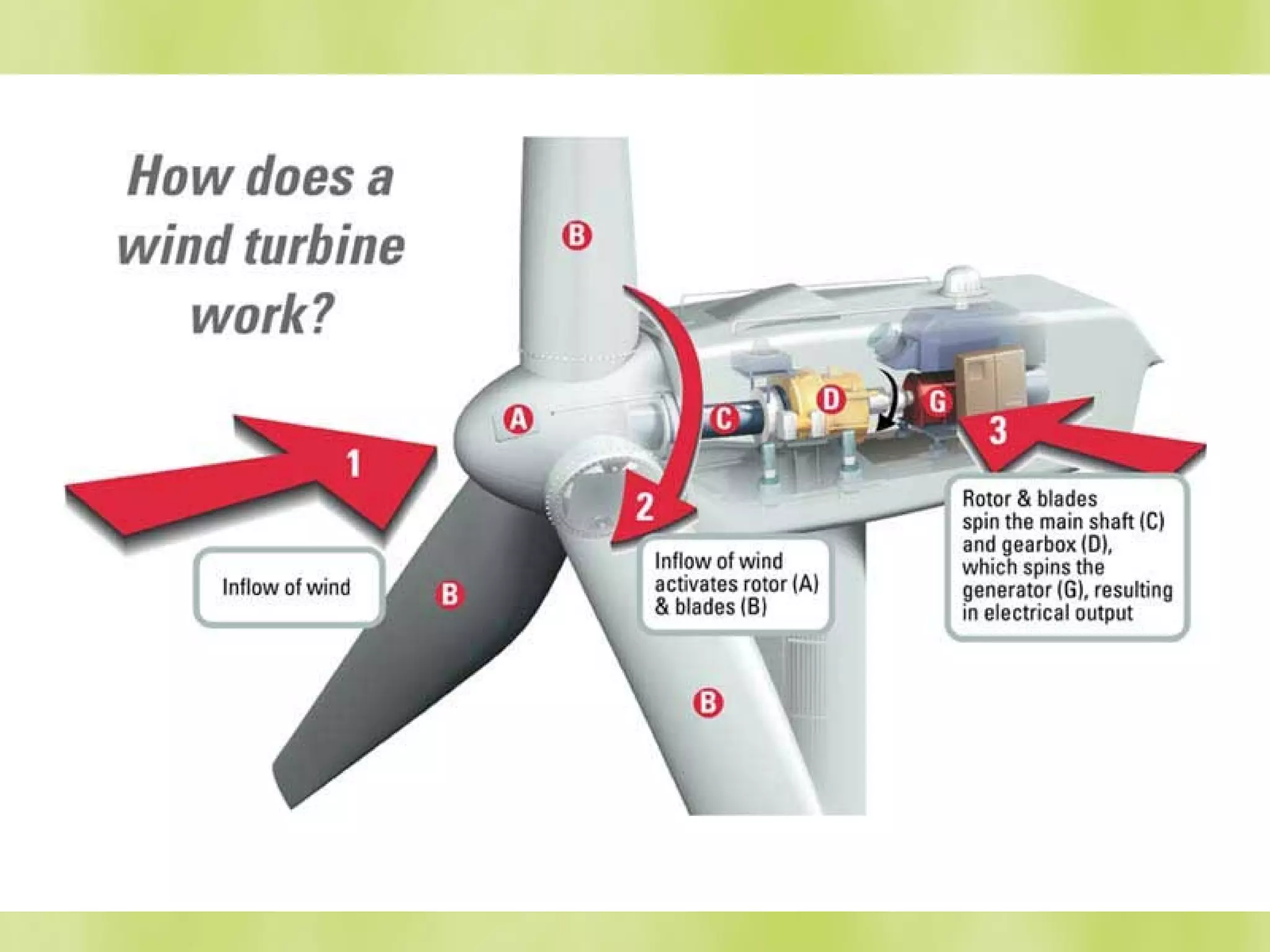
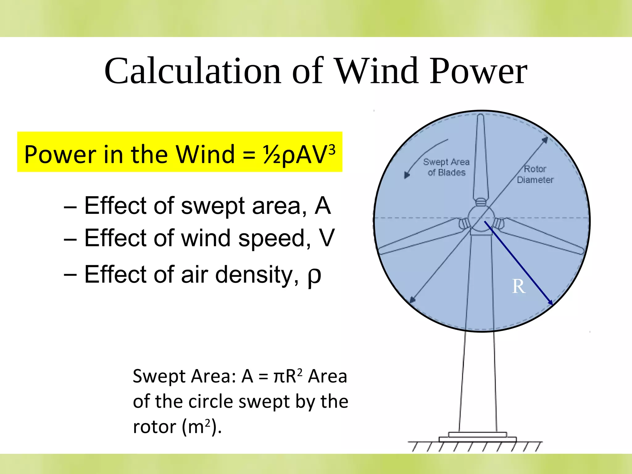


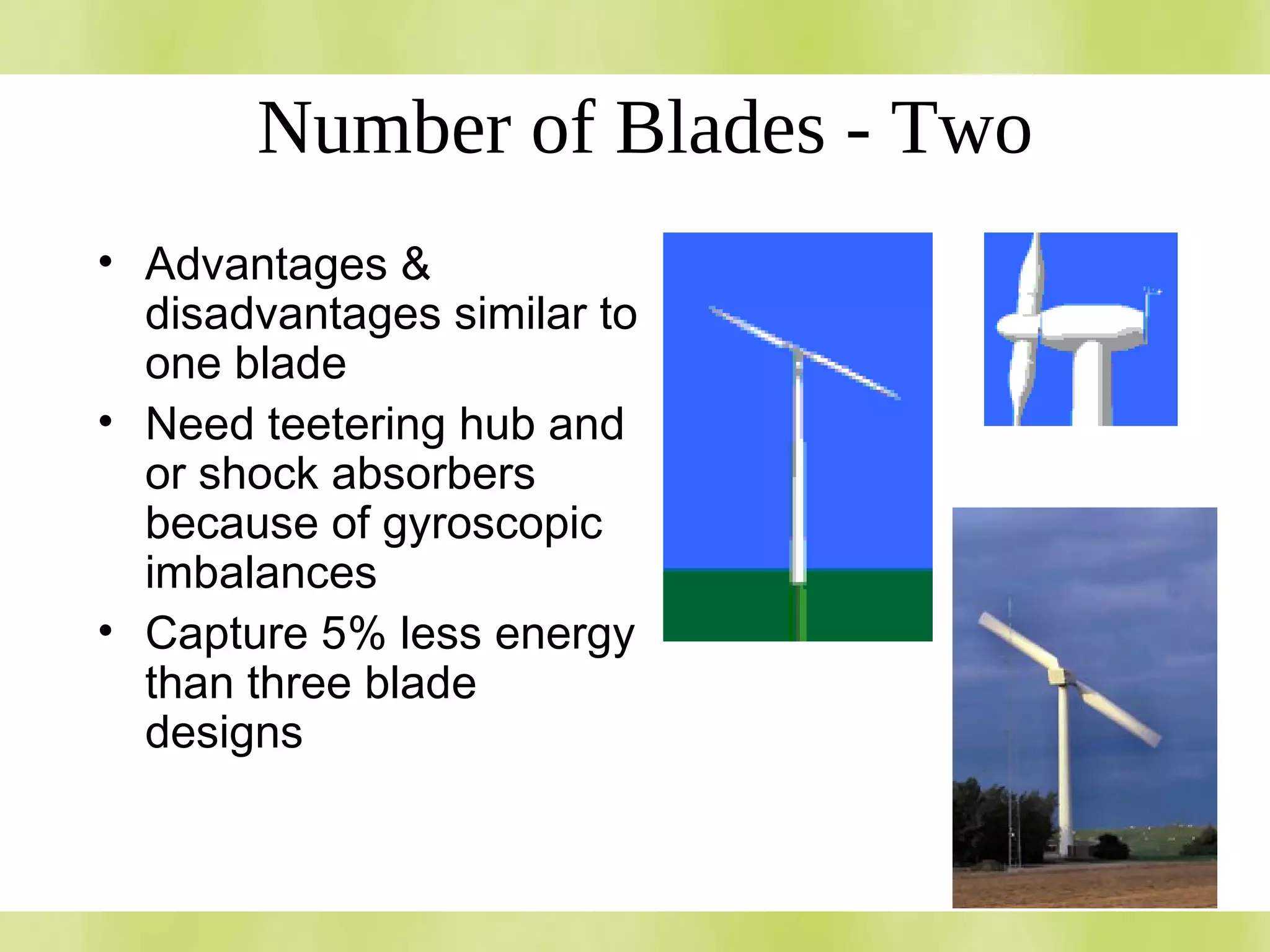
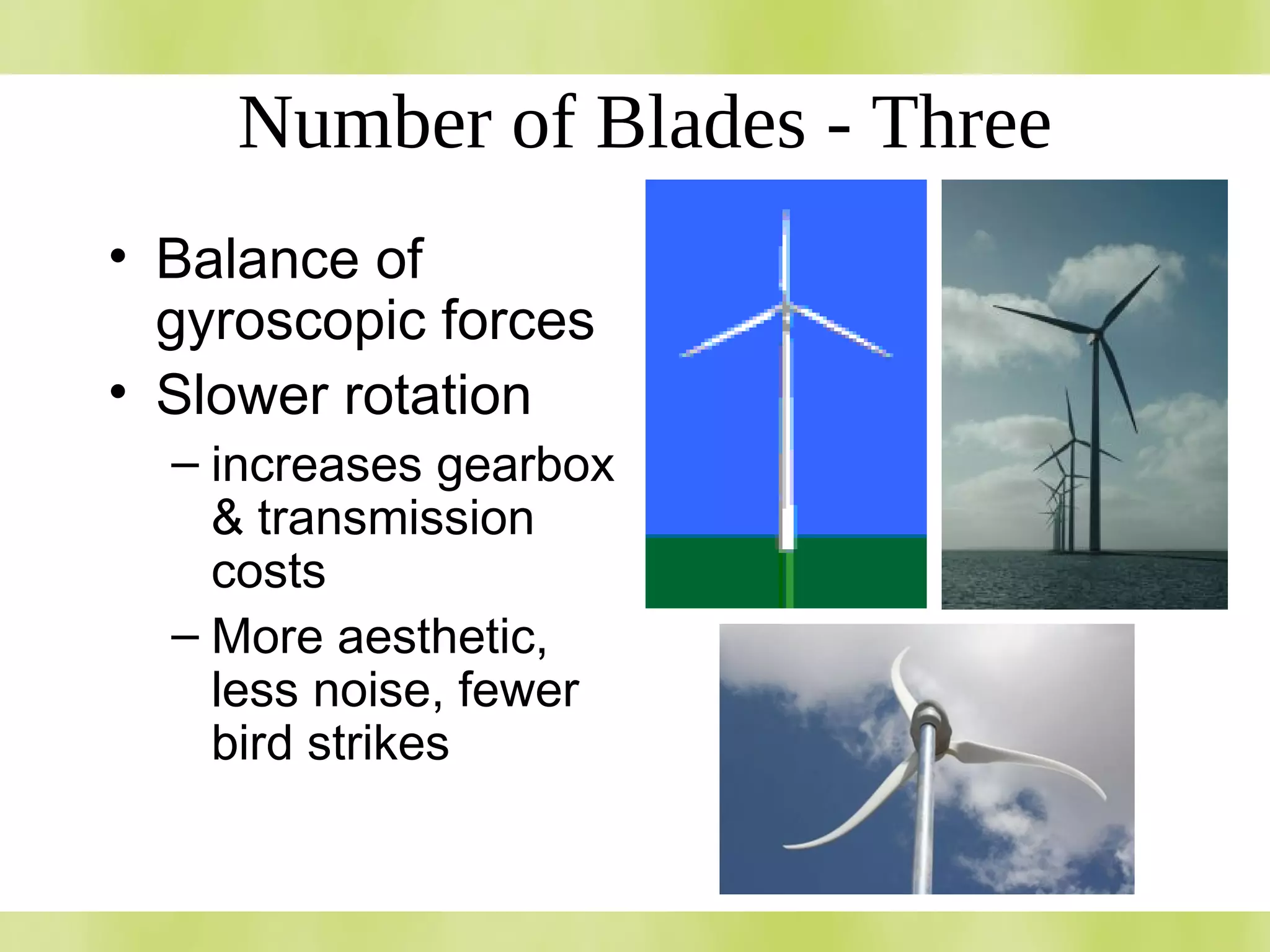
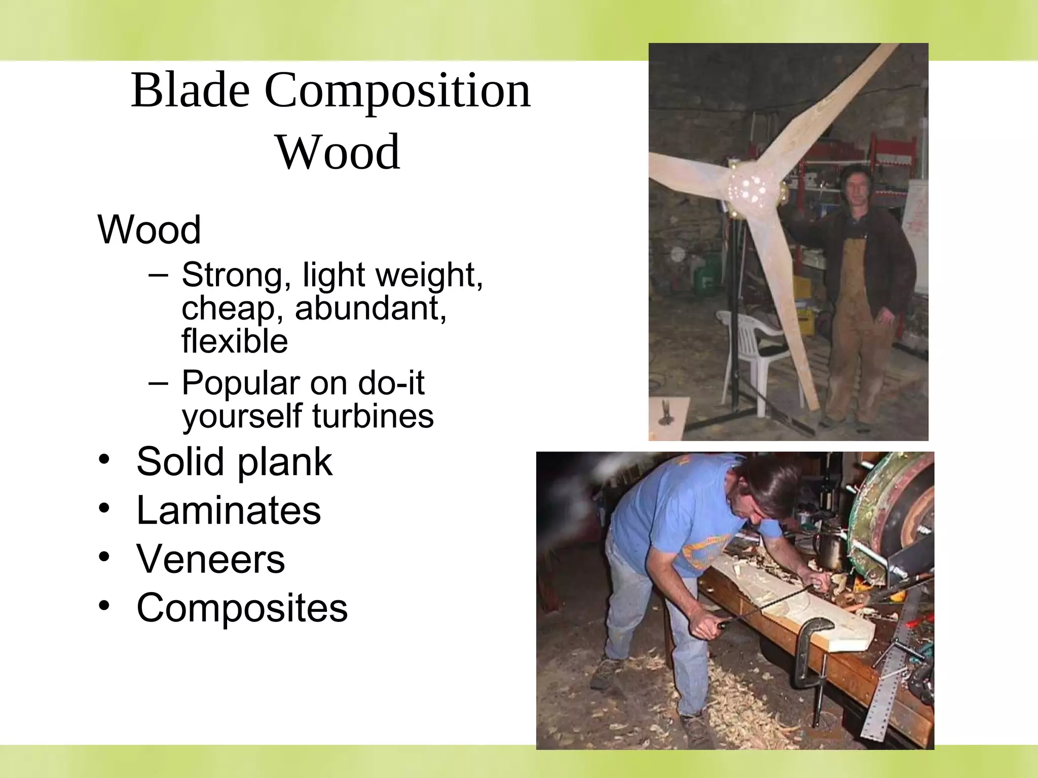
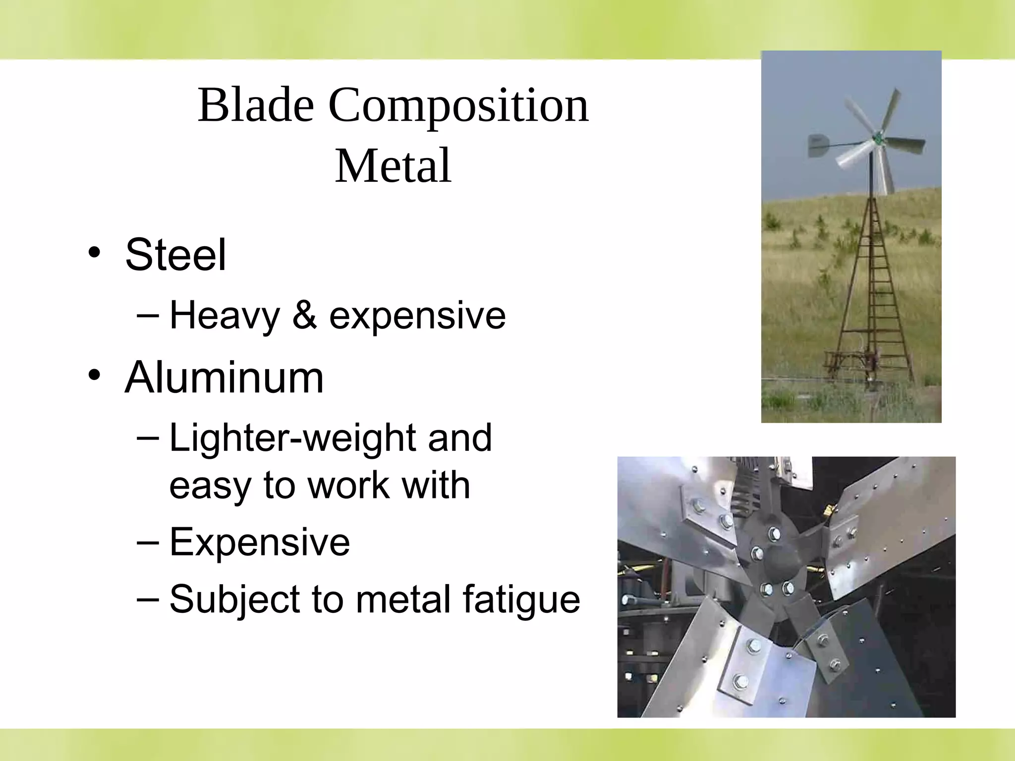
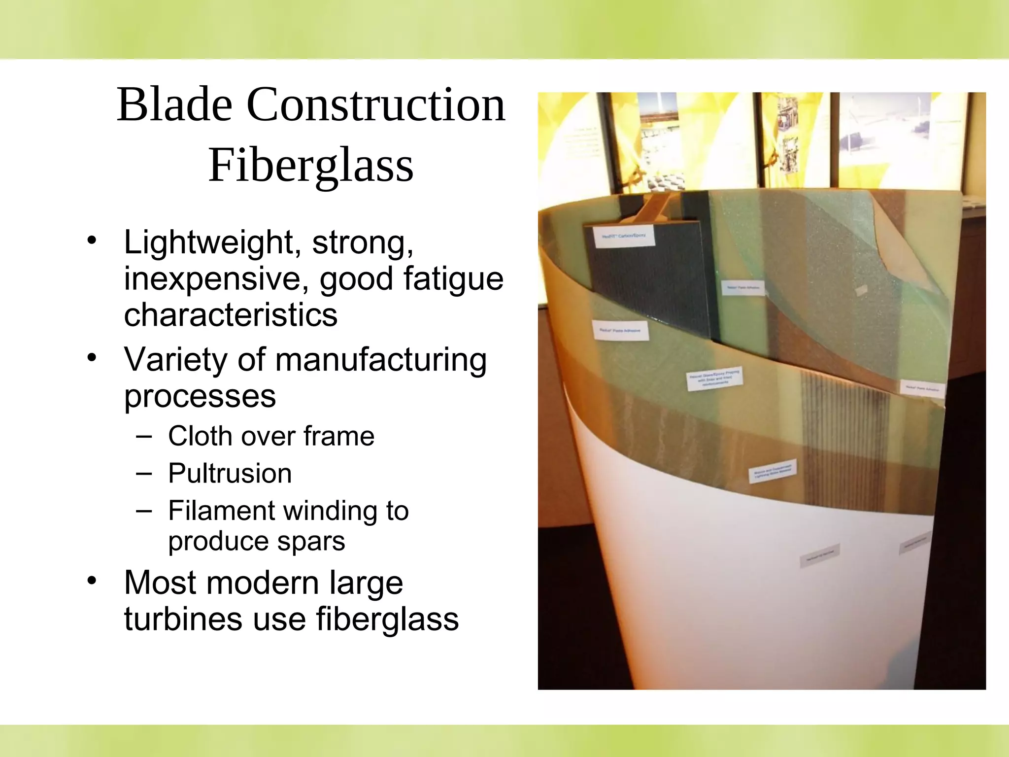

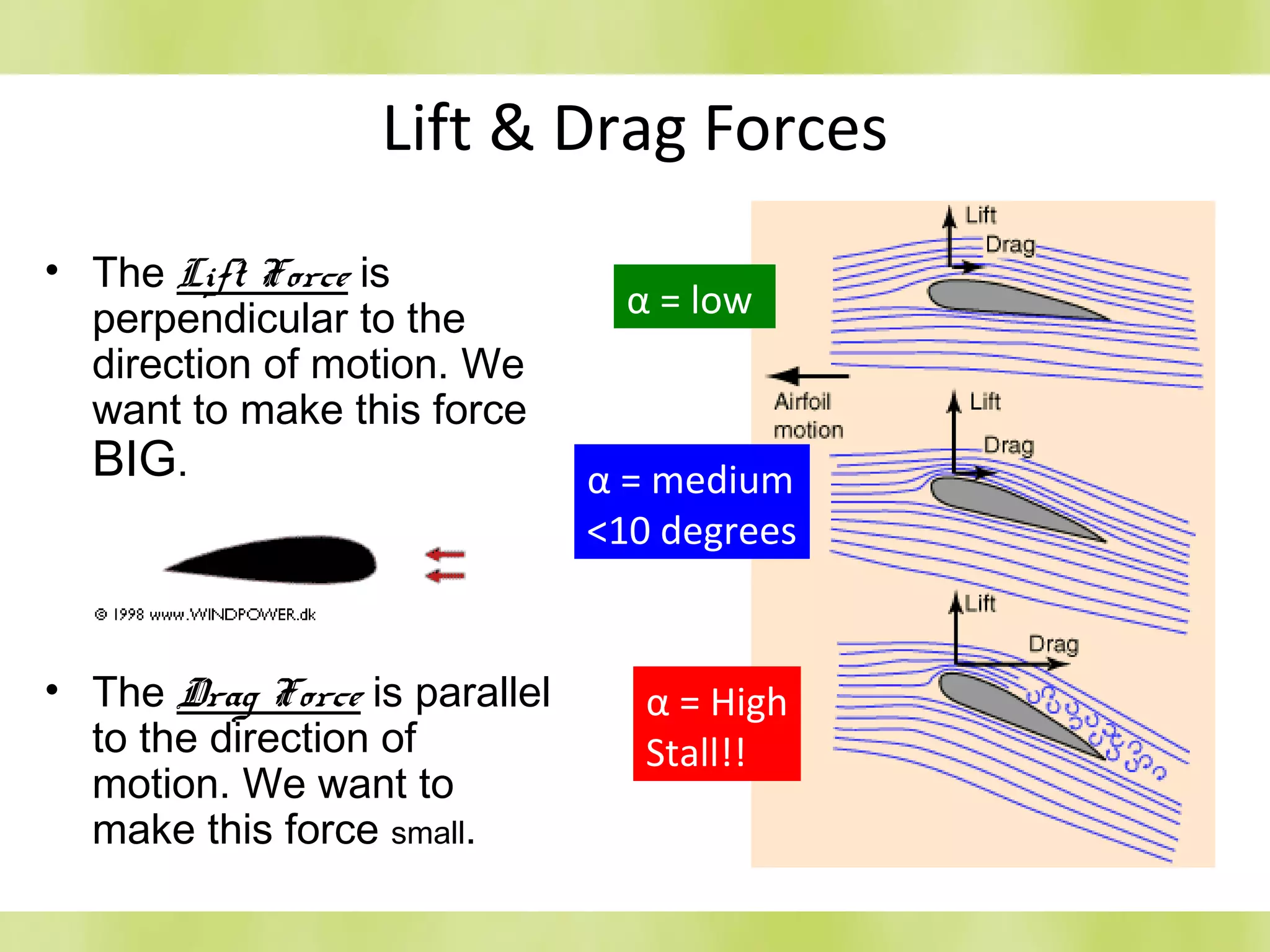
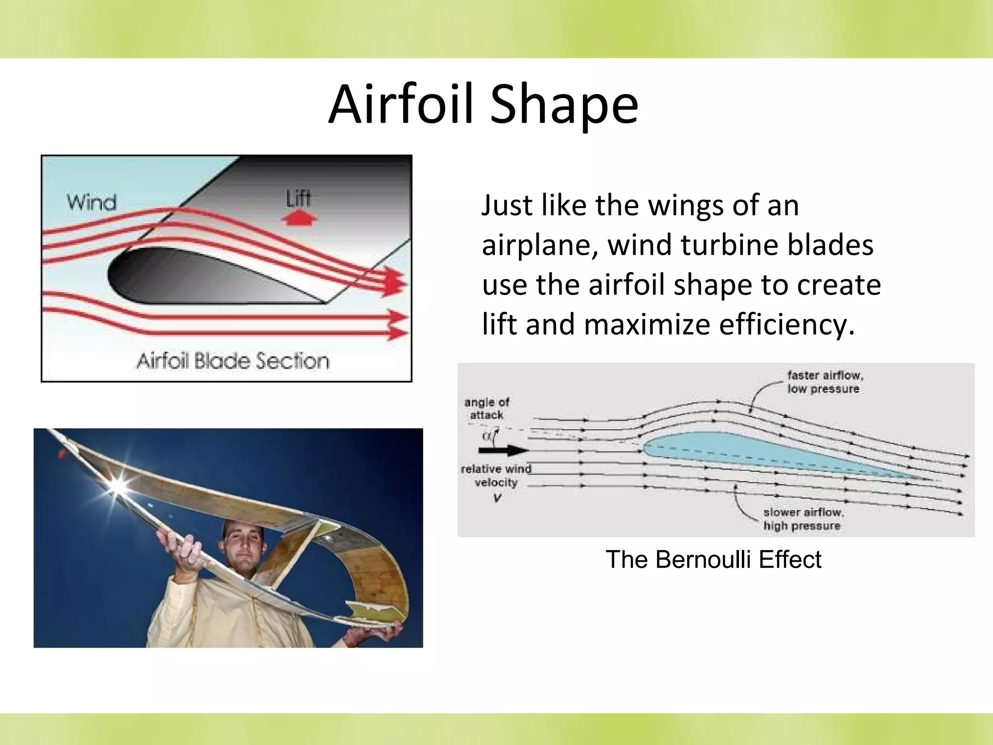
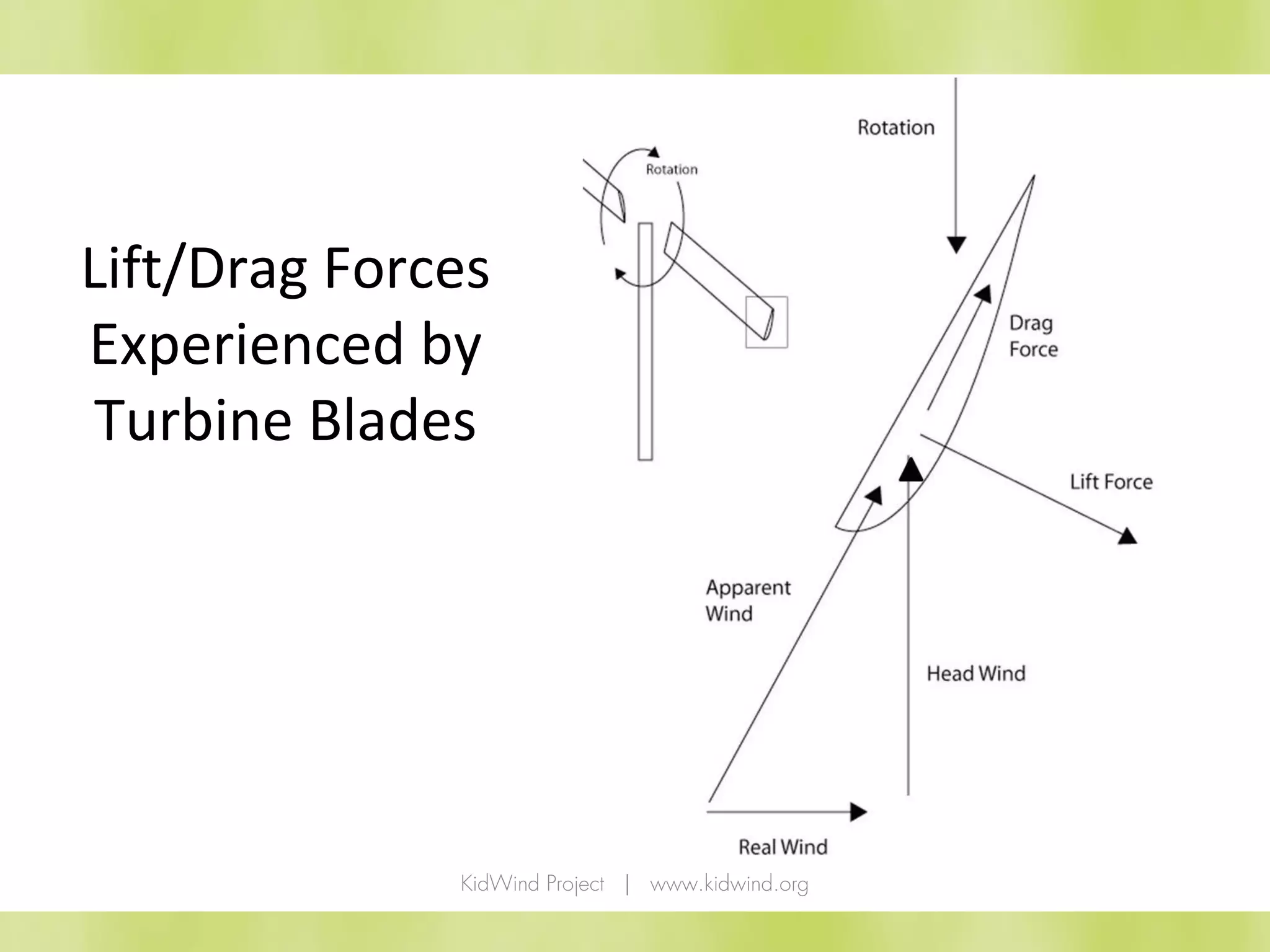
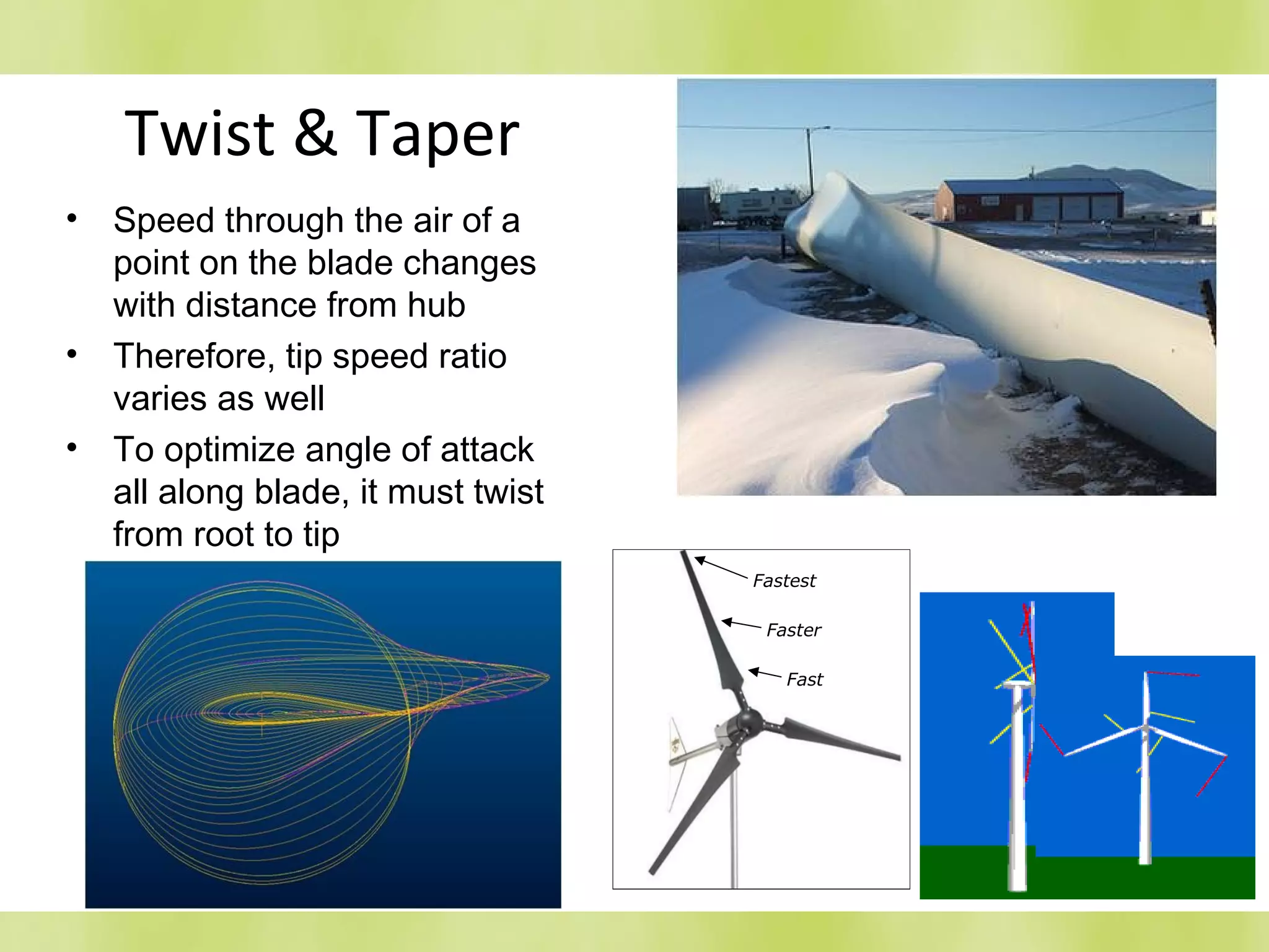

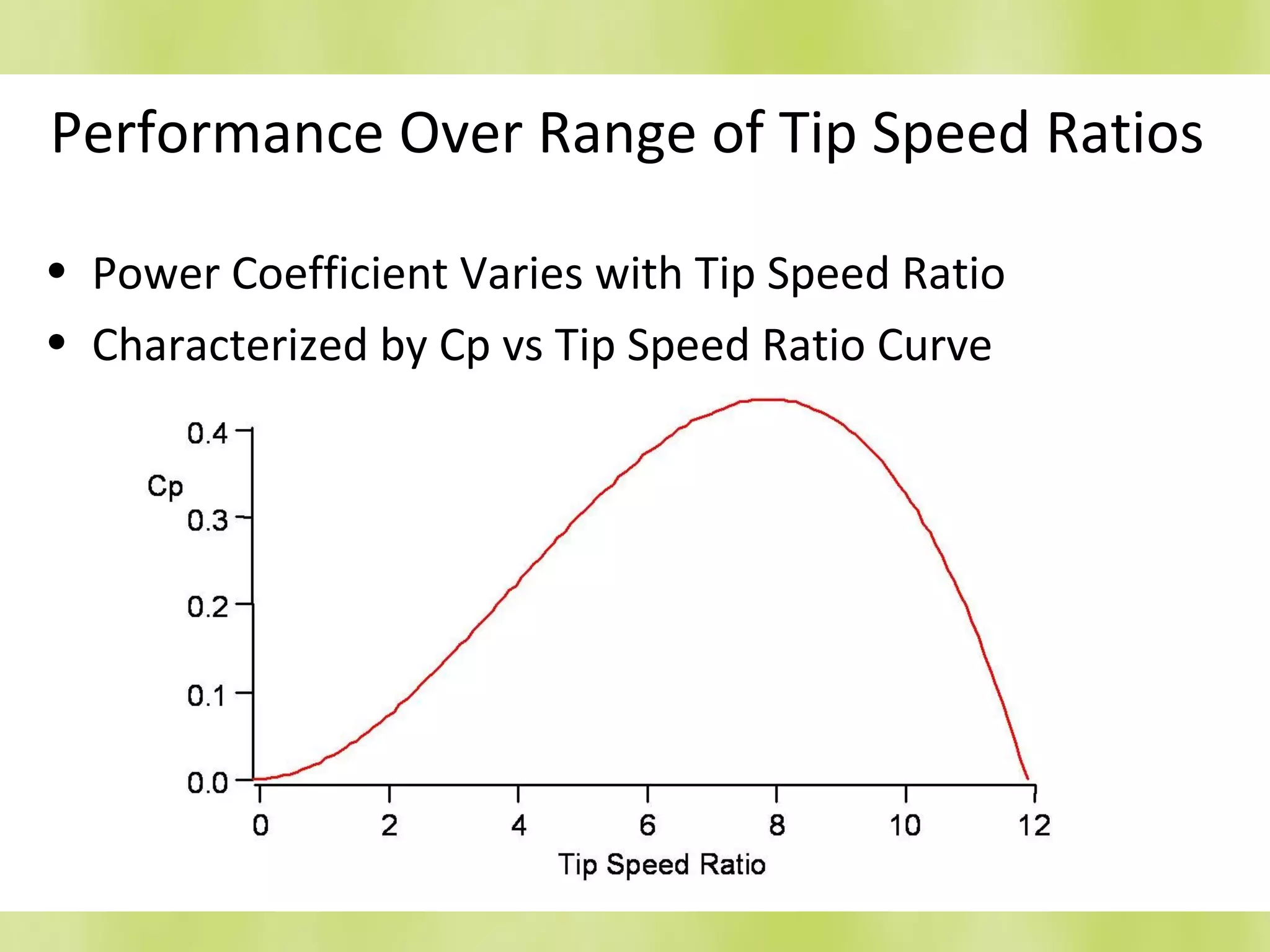


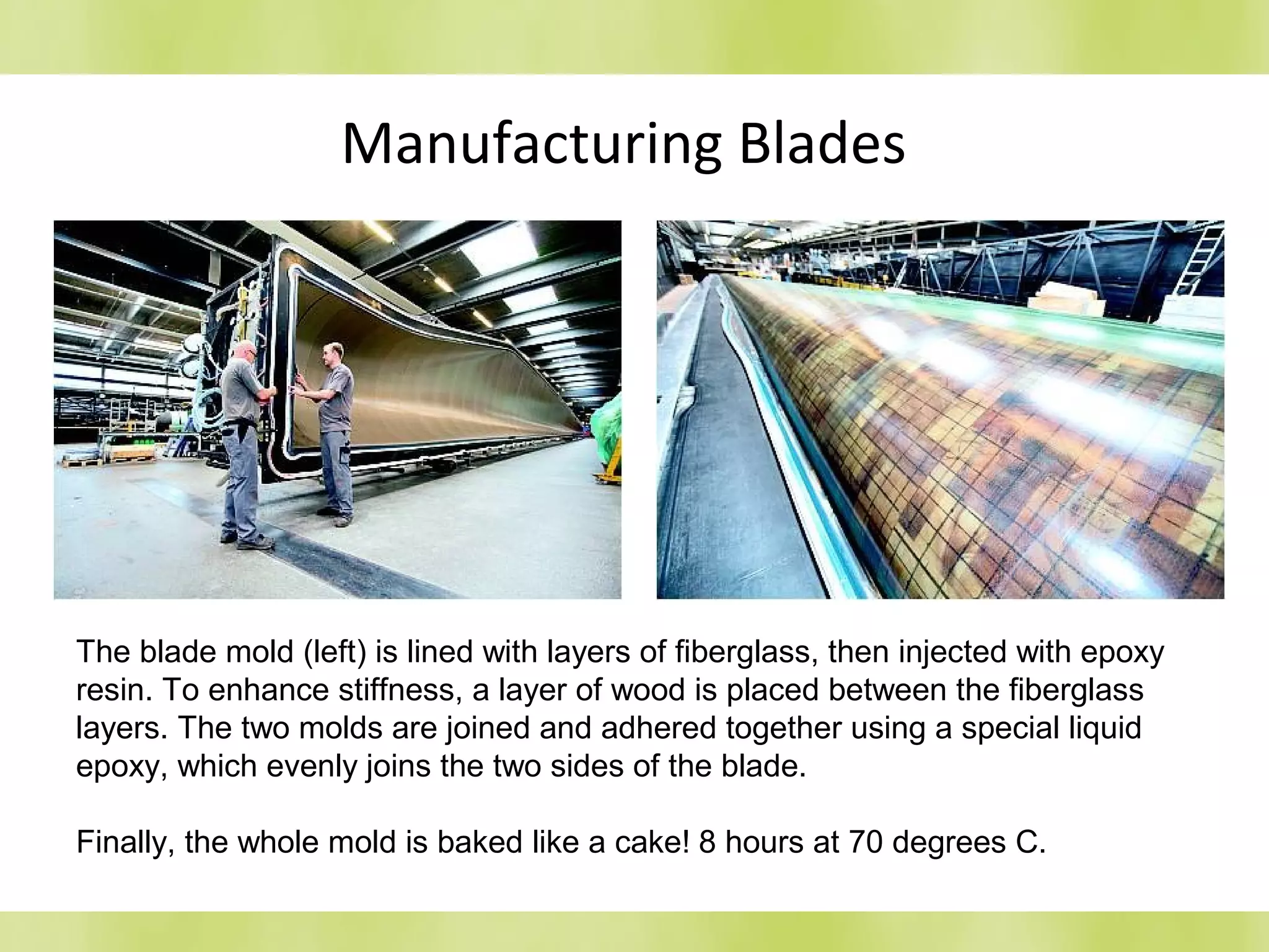
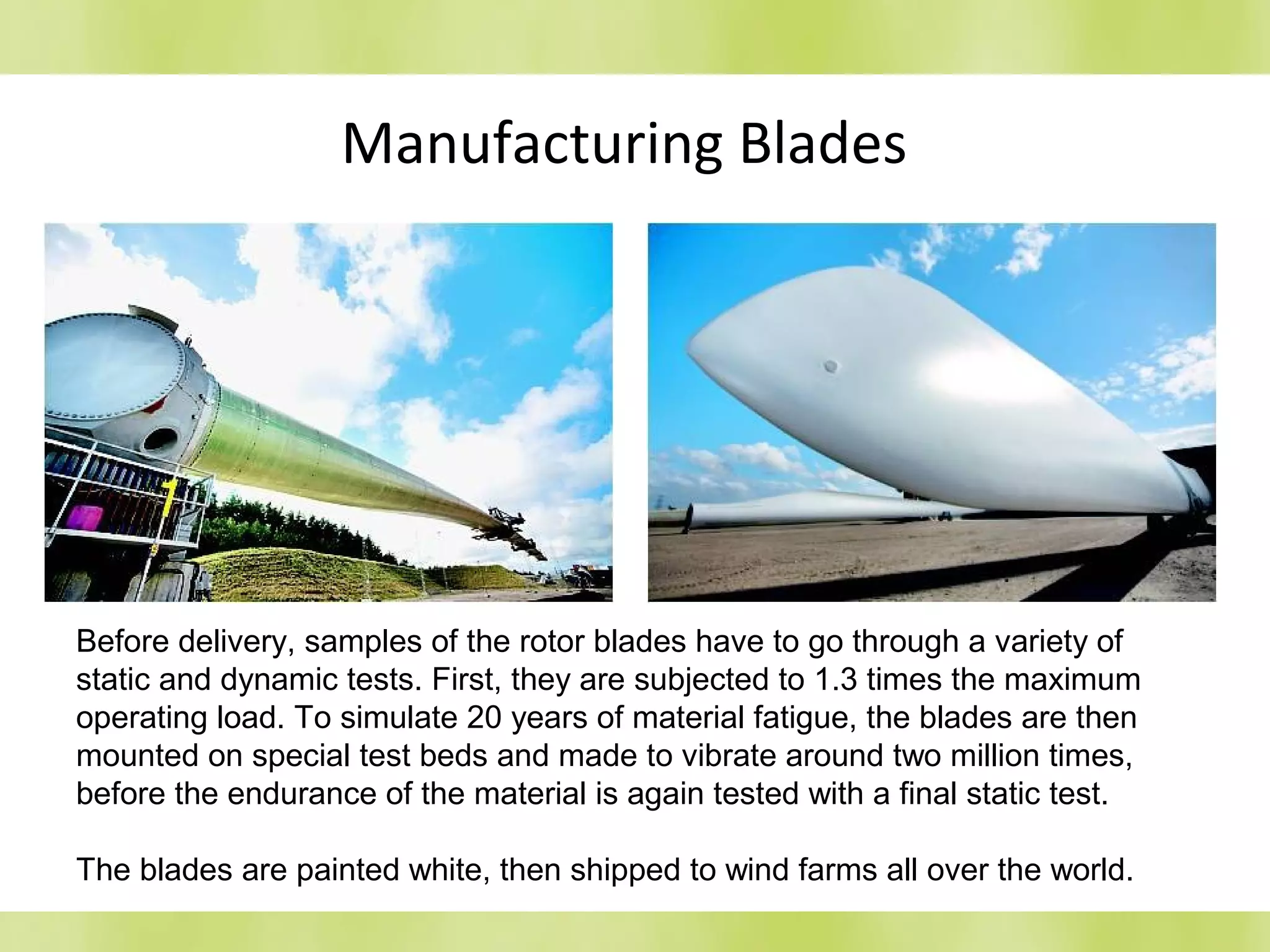
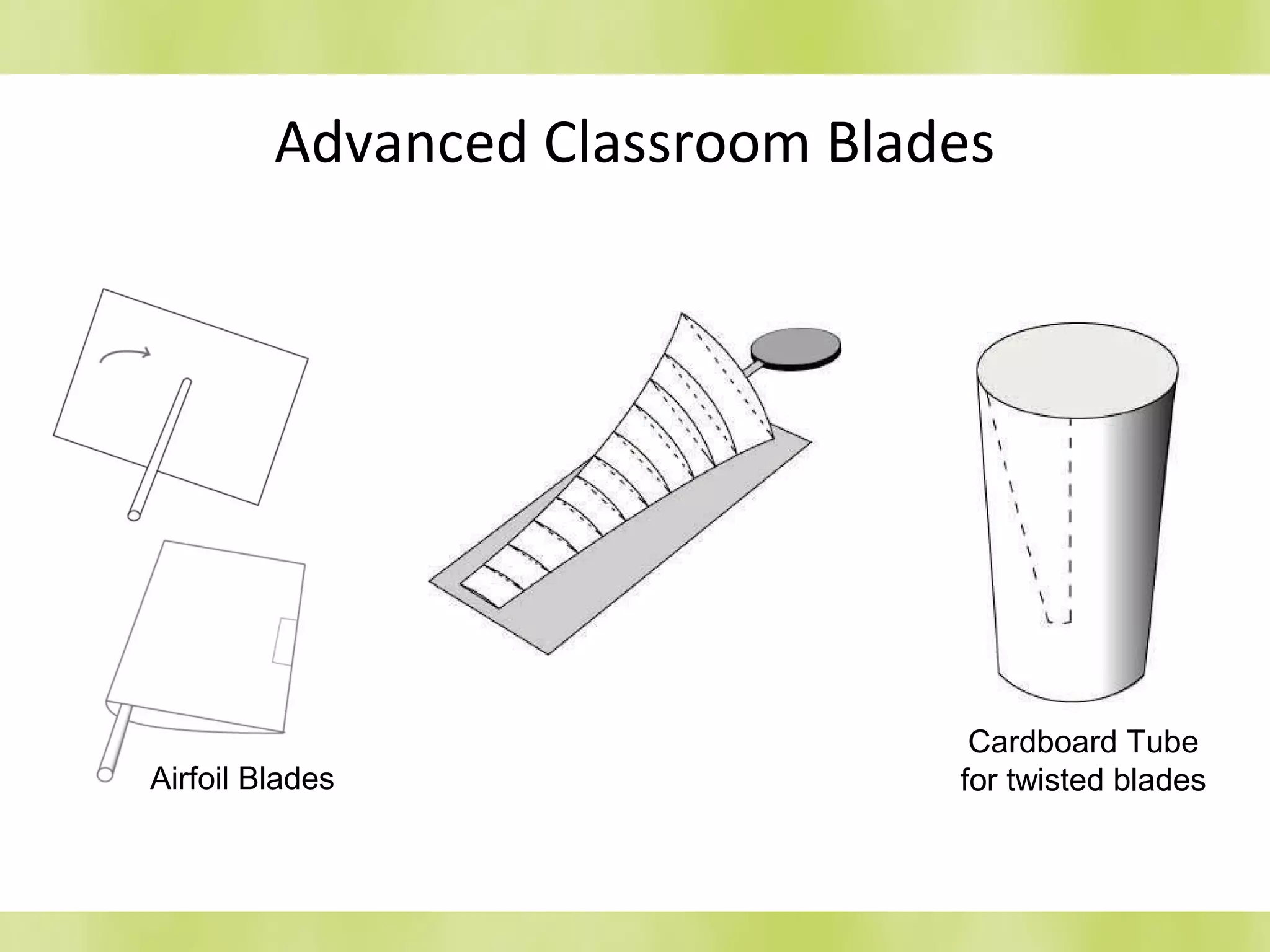
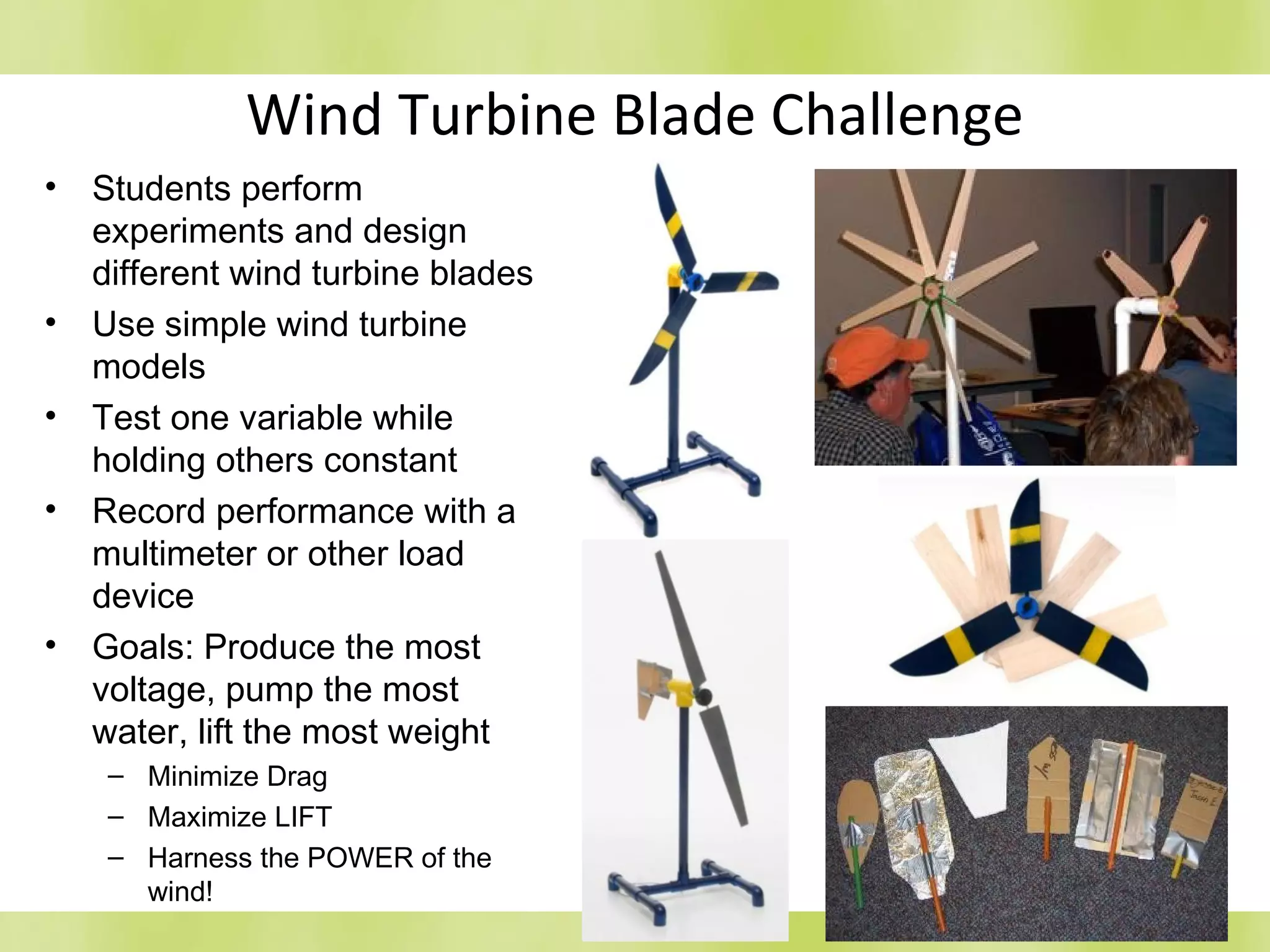


This document discusses various design considerations for wind turbine blades. It begins by explaining how wind power is calculated based on swept area, wind speed, and air density. It then discusses different blade designs including the number of blades (one, two, or three blades are common), blade composition (wood, metal, fiberglass are options), construction techniques, airfoil shape to maximize lift and minimize drag, and twist and taper along the blade's length. Additional topics covered include tip-speed ratio, performance curves, the Betz limit on maximum energy capture, rotor solidity, pitch control mechanisms, and blade manufacturing processes. The document concludes by discussing classroom wind turbine blade challenge activities.


