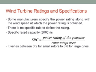
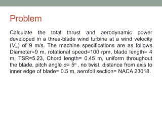
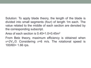
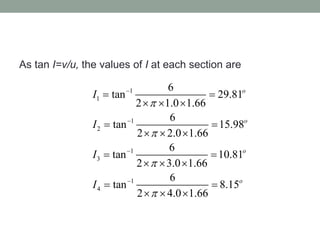
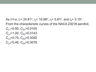
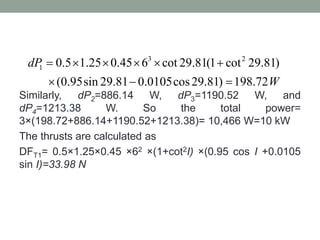
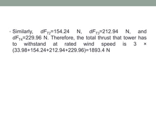
IMPORTANT TERMS
Dr. Ashwini Kumar Nayak
Asst. Professor,
School of Electrical Sciences
NIST, Berhampur
Solidity
• The solidity of a wind rotor is the ratio of the projected
blade area to the area of the wind intercepted.
• The projected blade area does not mean the actual blade
area.
• It is the blade area met by the wind or projected in the
direction of the wind.
• For Savonius rotor is naturally unity, as the wind sees no
free passage through it.
• For multiblade water-pumping windmill is around 0.7.
• For high-speed horizontal-axis machines, it lies between
0.01 and 0.1; it is same for Darrieus rotor.
• Solidity has a direct relationship with torque and speed.
• High-solidity rotors have high torque and low speed, and
are suitable for pumping water.
• Low-solidity rotors have high speed and low torque, and
are typically suited for electrical power generation.
Tip Speed Ratio
• The tip speed ratio (TSR) of a wind turbine is
where λ is the TSR (Non-dimensional), R is the radius of
the swept area (in meters), N is the rotational speed in
revolutions per second, and V∞ is the wind speed without
rotor interruption (in meters per second).
2 RN
V




• For the Savonius rotor and the multiblade water-pumping
windmills are generally low.
• In high-speed horizontal-axis rotors and Darrieus rotors,
the outer tip actually turns much faster than the wind
speed owing to the aerodynamic shape. Thus, the TSR
can be as high as 9.
• High-solidity rotors have low TSRs and vice versa.
Power Coefficient
• The power coefficient of a wind energy converter is
• Power coefficient differs from the efficiency of a wind
machine.
• Efficiency includes the losses in mechanical transmission,
electrical generation, etc.
• Power coefficient is the efficiency of conversion of wind
energy into mechanical energy to the shaft.
P
power output fromthe wind machine
C
power contained in wind

• In high-speed horizontal-axis machines, the theoretical
maximum power coefficient is given by the Betz limit.
Wind Turbine Ratings and Specifications
• Some manufacturers specify the power rating along with
the wind speed at which the power rating is obtained.
• There is no specific rule to define the rating.
• Specific rated capacity (SRC) is
• It varies between 0.2 for small rotors to 0.6 for large ones.
power rating of the genrator
SRC
rotor swept area

Problem
Calculate the total thrust and aerodynamic power
developed in a three-blade wind turbine at a wind velocity
(V∞) of 9 m/s. The machine specifications are as follows
Diameter=9 m, rotational speed=100 rpm, blade length= 4
m, TSR=5.23, Chord length= 0.45 m, uniform throughout
the blade, pitch angle α= 5o , no twist, distance from axis to
inner edge of blade= 0.5 m, aerofoil section= NACA 23018.
Solution: To apply blade theory, the length of the blade is
divided into small segments (four) of length 1m each. The
value related to the middle of each section are denoted by
the corresponding subscript.
Area of each section is 0.45×1.0=0.45m2
From Betz theory, maximum efficiency is obtained when
v=2V∞/3. Considering v=6 m/s. The rotational speed is
100/60= 1.66 rps.
As tan I=v/u, the values of I at each section are
1
1
1
2
1
3
1
4
6
tan 29.81
2 1.0 1.66
6
tan 15.98
2 2.0 1.66
6
tan 10.81
2 3.0 1.66
6
tan 8.15
2 4.0 1.66
o
o
o
o
I
I
I
I








 
  
 
  
 
  
 
  
As i=I-α, i1= 24.81o, i2= 10.98o, i3= 5.81o, and i4= 3.15o.
From the characteristic curves of the NACA 23018 aerofoil,
CL1=0.95, CD1=0.0105
CL2=1.20, CD2=0.0143
CL3=0.75, CD3=0.0092
CL4=0.46, CD4=0.0078
Similarly, dP2=886.14 W, dP3=1190.52 W, and
dP4=1213.38 W. So the total power=
3×(198.72+886.14+1190.52+1213.38)= 10,466 W=10 kW
The thrusts are calculated as
DFT1= 0.5×1.25×0.45 ×62 ×(1+cot2I) ×(0.95 cos I +0.0105
sin I)=33.98 N
3 2
1 0.5 1.25 0.45 6 cot 29.81(1 cot 29.81)
(0.95sin 29.81 0.0105cos29.81) 198.72
dP
W
     
  
• Similarly, dFT2=154.24 N, dFT3=212.94 N, and
dFT4=229.96 N. Therefore, the total thrust that tower has
to withstand at rated wind speed is 3 ×
(33.98+154.24+212.94+229.96)=1893.4 N

Important terms.pptx

  • 1.
    IMPORTANT TERMS Dr. AshwiniKumar Nayak Asst. Professor, School of Electrical Sciences NIST, Berhampur
  • 2.
    Solidity • The solidityof a wind rotor is the ratio of the projected blade area to the area of the wind intercepted. • The projected blade area does not mean the actual blade area. • It is the blade area met by the wind or projected in the direction of the wind.
  • 3.
    • For Savoniusrotor is naturally unity, as the wind sees no free passage through it. • For multiblade water-pumping windmill is around 0.7. • For high-speed horizontal-axis machines, it lies between 0.01 and 0.1; it is same for Darrieus rotor.
  • 4.
    • Solidity hasa direct relationship with torque and speed. • High-solidity rotors have high torque and low speed, and are suitable for pumping water. • Low-solidity rotors have high speed and low torque, and are typically suited for electrical power generation.
  • 5.
    Tip Speed Ratio •The tip speed ratio (TSR) of a wind turbine is where λ is the TSR (Non-dimensional), R is the radius of the swept area (in meters), N is the rotational speed in revolutions per second, and V∞ is the wind speed without rotor interruption (in meters per second). 2 RN V    
  • 6.
    • For theSavonius rotor and the multiblade water-pumping windmills are generally low. • In high-speed horizontal-axis rotors and Darrieus rotors, the outer tip actually turns much faster than the wind speed owing to the aerodynamic shape. Thus, the TSR can be as high as 9. • High-solidity rotors have low TSRs and vice versa.
  • 7.
    Power Coefficient • Thepower coefficient of a wind energy converter is • Power coefficient differs from the efficiency of a wind machine. • Efficiency includes the losses in mechanical transmission, electrical generation, etc. • Power coefficient is the efficiency of conversion of wind energy into mechanical energy to the shaft. P power output fromthe wind machine C power contained in wind 
  • 8.
    • In high-speedhorizontal-axis machines, the theoretical maximum power coefficient is given by the Betz limit.
  • 9.
    Wind Turbine Ratingsand Specifications • Some manufacturers specify the power rating along with the wind speed at which the power rating is obtained. • There is no specific rule to define the rating. • Specific rated capacity (SRC) is • It varies between 0.2 for small rotors to 0.6 for large ones. power rating of the genrator SRC rotor swept area 
  • 10.
    Problem Calculate the totalthrust and aerodynamic power developed in a three-blade wind turbine at a wind velocity (V∞) of 9 m/s. The machine specifications are as follows Diameter=9 m, rotational speed=100 rpm, blade length= 4 m, TSR=5.23, Chord length= 0.45 m, uniform throughout the blade, pitch angle α= 5o , no twist, distance from axis to inner edge of blade= 0.5 m, aerofoil section= NACA 23018.
  • 11.
    Solution: To applyblade theory, the length of the blade is divided into small segments (four) of length 1m each. The value related to the middle of each section are denoted by the corresponding subscript. Area of each section is 0.45×1.0=0.45m2 From Betz theory, maximum efficiency is obtained when v=2V∞/3. Considering v=6 m/s. The rotational speed is 100/60= 1.66 rps.
  • 12.
    As tan I=v/u,the values of I at each section are 1 1 1 2 1 3 1 4 6 tan 29.81 2 1.0 1.66 6 tan 15.98 2 2.0 1.66 6 tan 10.81 2 3.0 1.66 6 tan 8.15 2 4.0 1.66 o o o o I I I I                            
  • 13.
    As i=I-α, i1=24.81o, i2= 10.98o, i3= 5.81o, and i4= 3.15o. From the characteristic curves of the NACA 23018 aerofoil, CL1=0.95, CD1=0.0105 CL2=1.20, CD2=0.0143 CL3=0.75, CD3=0.0092 CL4=0.46, CD4=0.0078
  • 14.
    Similarly, dP2=886.14 W,dP3=1190.52 W, and dP4=1213.38 W. So the total power= 3×(198.72+886.14+1190.52+1213.38)= 10,466 W=10 kW The thrusts are calculated as DFT1= 0.5×1.25×0.45 ×62 ×(1+cot2I) ×(0.95 cos I +0.0105 sin I)=33.98 N 3 2 1 0.5 1.25 0.45 6 cot 29.81(1 cot 29.81) (0.95sin 29.81 0.0105cos29.81) 198.72 dP W         
  • 15.
    • Similarly, dFT2=154.24N, dFT3=212.94 N, and dFT4=229.96 N. Therefore, the total thrust that tower has to withstand at rated wind speed is 3 × (33.98+154.24+212.94+229.96)=1893.4 N