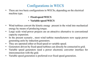
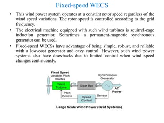
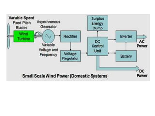
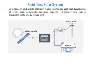
call girls in Kamla Market (DELHI) 🔝 >༒9953330565🔝 genuine Escort Service 🔝✔️✔️
Unit 4
1. Unit-IV
Grid Tied Wind and PV Systems
BY
R.ARULJOTHI
M.Tech( 2nd YEAR)
15EE302
Under the guidance of
DR. N.P. SUBRAMANIAM, M.E.,Ph.D.,
ASSISTANT PROFESSOR
DEPARTMENT OF ELECTRICALAND ELECTRONICS
ENGINEERING
PONDICHERRY ENGINEERING COLLEGE
2. WIND ENERGY CONVERSION SYSTEMS
• Wind turbine development has become an attractive research topic in
renewable energy resources in recent years.
• Wind energy conversion systems (WECSs) have been intensively
developed to contribute the “green energy” demand up 20% by 2030.
• Clearly, energy specialists and policy makers have realized the potential
importance of wind energy resource in common energy crisis in the world
nowadays.
• For technical aspects, many of opportunities being pursued through
advanced control techniques are utilized to achieve higher contribution of
wind energy.
• Wind turbine is a device that converts mechanical energy from wind into
electrical energy to be used in stand-alone grid or to be connected with the
grid.
3. Parts of the Wind Turbine
• A typical wind turbine consists of necessary components, illustrated in the
following figure
4. Configurations in WECS
• There are two basic configurations in WECSs, depending on the electrical
machine type.
• Fixed-speed WECS
• Variable-speed WECS
• Wind turbines convert the kinetic energy present in the wind into mechanical
energy by means of producing torque.
• Large scale wind power projects are an attractive alternative to conventional
capacity expansion.
• In the present scenario , most wind turbine manufacturers now equip power
generating units by induction generators.
• They are operated either at fixed speed or variable speed.
• Generators driven by fixed speed turbines can directly be connected to grid.
• Variable speed generators need a power electronic converter interface for
interconnection with the grid.
• Variable speed generation is preferred over fixed speed generation.
5. Fixed-speed WECS
• This wind power system operates at a constant rotor speed regardless of the
wind speed variations. The rotor speed is controlled according to the grid
frequency.
• The electrical machine equipped with such wind turbines is squirrel-cage
induction generator. Sometimes a permanent-magnetic synchronous
generator can be used.
• Fixed-speed WECSs have advantage of being simple, robust, and reliable
with a low-cost generator and easy control. However, such wind power
systems also have drawbacks due to limited control when wind speed
changes continuously.
6. • In early prototypes of fixed-speed wind turbines synchronous generators
have been used, but the induction machine appeared to be more widely
adopted because of its lower cost, better environmental durability and
superior mechanical compatibility with rapid wind changes.
• That is why in fixed-speed wind turbines the generator used is the
induction generator type, directly connected to the grid.
• In the majority of wind turbines designs the generator is connected with the
hub with blades via a gearbox. They are placed in a nacelle on the top of
the turbine tower.
• The gearbox is needed to change the low rotational speed of the turbine to a
high rotational speed on the generator. The induction generators rotational
speed is typically 1000 or 1500 rpm.
• The speed of the turbine is dependent on its rotor diameter. For example a
330 kW turbine has a rotational speed of approximately 18 - 45 rpm, while
the rotational speed of a 1670 kW turbine is approximately 10 - 19 rpm.
• A fixed-speed wind turbine is designed to obtain maximum efficiency at
one wind speed that will give the optimum tip speed to wind speed ratio for
the rotor airfoil. In order to be able to capture more wind energy, some
fixed-speed wind turbines have two different rotational speeds.
• This can be achieved either by placing two generators in the nacelle or by
one generator having two separate windings.
7. Variable-speed WECS
• Comparing with fixed-speed wind turbines, variable-speed WECSs based
on a doubly-fed induction generator (DFIG) offer a number of merits such
as simple control, four-quadrant active and reactive power regulation, and
low cost converter.
• With a DFIG-based wind system, the stator side is directly connected to the
grid, whereas the rotor side is connected to a back-to-back voltage source
inverter. The stator outputs power into the grid.
• The rotor is capable of delivering or absorbing power to/from the grid,
depending on the rotor speed.
• With a PMSG-based wind system, the generator output voltage and
frequency are proportional to the rotor speed and the current is proportional
to the torque on the shaft.
• The output is rectified and fed through a buck-boost regulator to an
inverter which generates the required fixed amplitude and frequency AC
voltage.
8. • There are many similarities in major components construction of fixed-
speed wind turbines and wind turbines operating within a narrow variable-
speed range.
• Fixed-speed wind turbines operating within a narrow speed range usually
use a double-fed induction generator and have a converter connected to the
rotor circuit.
• The rotational speed of the double-fed induction generator equally 1000 or
1500 rpm, so a gearbox implementation is required.
• To simplify the nacelle design a direct-driven generator is used. A direct-
driven generator using a large turbine blades diameter can operate at a very
low speeds and does not need a gearbox installed to increase to speed.
• The usage of frequency converter is needed to use a direct-driven
generator, so wind turbines operating within a broad variable-speed range
are equipped with a frequency converter.
• In an conventional fixed-speed wind turbine, the gearbox and the generator
have to be mounted on a stiff bed plate and aligned precisely in respect to
each other.
• A direct driven generator can be integrated with the nacelle, so the
generator housing and support structure are also the main parts of the
nacelle construction.
11. Synchronous Generator with In-Line Frequency
Control
• Rather than controlling the turbine rotation speed to obtain a fixed
frequency synchronised with the grid from a synchronous generator, the
rotor and turbine can be run at a variable speed corresponding to the
prevailing wind conditions.
• This will produce a varying frequency output from the generator
synchronised with the drive shaft rotation speed. This output can then be
rectified in the generator side of an AC-DC-AC converter and the
converted back to AC in an inverter in grid side of the converter which is
synchronised with the grid frequency.
• The grid side converter can also be used to provide reactive power (VArs)
to the grid for power factor control and voltage regulation by varying the
firing angle of the thyristor switching in the inverter and thus the phase of
the output current with respect to the voltage.
12. • The range of wind speeds over which the system can be operated can be
extended and mechanical safety controls can be incorporated by means of
an optional speed control system based on pitch control of the rotor vanes
as used in the fixed speed system described above.
• One major drawback of this system is that the components and the
electronic control circuits in the frequency converter must be dimensioned
to carry the full generator power.
13. Doubly Fed Induction Generator
• Wind turbines use a doubly-fed induction generator (DFIG) consisting of a
wound rotor , induction generator and an AC/DC/AC IGBT-based PWM
converter.
• The stator winding is connected directly to the grid while the rotor is fed at
variable frequency through the AC/DC/AC converter.
• Vr is the rotor voltage and Vgc is grid side voltage.
• The AC/DC/AC converter is basically a PWM converter which uses
sinusoidal PWM technique to reduce the harmonics present in the wind
turbine driven DFIG system.
• Crotor is rotor side converter and Cgrid is grid side converter.
• To control the speed of wind turbine gear boxes or electronic control can be
used.
15. Operating Principal of DFIG
• Below the synchronous speed in the motoring mode and above the
synchronous speed in the generating mode, rotor-side converter operates as
a rectifier and stator-side converter as an inverter and where slip power is
returned to the stator.
• Below the synchronous speed in the generating mode and above the
synchronous speed in the motoring mode, rotor-side converter operates as
an inverter and stator side converter as a rectifier, where slip power is
supplied to the rotor.
• For super synchronous speed operation, Pr is transmitted to DC bus
capacitor and tends to rise the DC voltage. For sub-synchronous speed
operation, Pr is taken out of DC bus capacitor and tends to decrease the DC
voltage.
• Cgrid is used to generate or absorb the power Pgc in order to keep the DC
voltage constant.
• In steady-state for a lossless AC/DC/AC converter Pgc is equal to Pr and
the speed of the wind turbine is determined by the power Pr absorbed or
generated by Crotor.
• The phase-sequence of the AC voltage generated by Crotor is positive for
sub synchronous speed and negative for super synchronous speed.
• Crotor and Cgrid have the capability for generating or absorbing reactive
power and could be used to control the reactive power or the voltage at the
grid terminals.
16. Wound-Rotor Induction Generator (WRIG) with
External Rotor Resistances
• The system configuration is the same as that of the fixed-speed wind
energy system except that the SCIG is replaced with the WRIG. The
external rotor resistance, is made adjustable by a converter composed of a
diode bridge and an IGBT chopper. The equivalent value of Rex, seen by
the rotor varies with the duty cycle of the chopper.
17. • Slip rings and brushes of the WRIG can be avoided in some
practical WECS by mounting the external rotor resistance circuit on
the rotor shaft. This reduces maintenance needs, but introduces
additional heat dissipation inside the generator.
• The main advantage of this configuration compared to the variable-
speed WECS is the low cost and simplicity.
• The major drawbacks include limited speed range, inability to
control grid-side reactive power, and reduced efficiency due to the
resistive losses.
18. SCIG Wind Energy Systems
with Full-Capacity Power Converters
With Two-Level Voltage Source Converters.
• The two converters are identical in topology and linked by a DC-link
capacitive filter. The generator and converters are typically rated for 690 V,
and each converter can handle up to 0.75 MW.
19. • For wind turbines larger than 0.75 MW, the power rating of the
converter can be increased by paralleling IGBT modules. Measures
should be taken to ensure minimum circulating current among the
parallel modules.
• To minimize the circulating current, issues such as dynamic and
static characteristics of IGBTs, design and arrangement of gate
driver circuits, and physical layout of IGBT modules and DC bus
should be considered.
• Some semiconductor manufacturers provide IGBT modules for
parallel operation to achieve a power rating of several megawatts.
20. Grid-Tied Solar System
• Grid-tied, on-grid, utility-interactive, grid intertie and grid back feeding are
all terms used to describe the same concept – a solar system that is
connected to the utility power grid.
21. Equipment for Grid-Tied Solar Systems
• There are a few key differences between the equipment needed for grid-
tied, off-grid and hybrid solar systems. Standard grid-tied solar systems
rely on the following components:
– Grid-Tie Inverter (GTI) or Micro-Inverters
– Power Meter
Grid-Tie Inverter (GTI)
• They regulate the voltage and current received from your solar
panels. Direct current (DC) from your solar panels is converted into
alternating current (AC), which is the type of current that is utilized by the
majority of electrical appliances.
• In addition to this, grid-tie inverters, also known as grid-interactive or
synchronous inverters, synchronize the phase and frequency of the current
to fit the utility grid (nominally 60Hz). The output voltage is also adjusted
slightly higher than the grid voltage in order for excess electricity to flow
outwards to the grid.
22. Micro-Inverters
• Micro-inverters go on the back of each solar panel, as opposed to one
central inverter that typically takes on the entire solar array.
• There has recently been a lot of debate on whether micro-inverters are
better than central (string) inverters.
• Micro-inverters are certainly more expensive, but in many cases yield
higher efficiency rates. Homeowners who are suspect to shading issues
should definitely look into if micro-inverters are better in their situation.
Power Meter
• Most homeowners will need to replace their current power meter with one
that is compatible with net metering. This device, often called a net meter
or a two-way meter, is capable of measuring power going in both
directions, from the grid to your house and vice versa.
• You should consult with your local utility company and see what net
metering options you have. In some places, the utility company issues a
power meter for free and pay full price for the electricity you generate;
however, this is not always the case.
23. Advantages of Grid-Tied Systems
Save more money with net metering
• A grid-connection will allow you to save more money with solar panels
through better efficiency rates, net metering, plus lower equipment and
installation costs:
• Batteries, and other stand-alone equipment, are required for a fully
functional off-grid solar system and add to costs as well as maintenance.
Grid-tied solar systems are therefore generally cheaper and simpler to
install.
The utility grid is a virtual battery
• Electricity has to be spent in real time. However, it can be temporarily
stored as other forms of energy (e.g. chemical energy in batteries). Energy
storage typically comes with significant losses.
• The electric power grid is in many ways also a battery, without the need for
maintenance or replacements, and with much better efficiency rates.
25. References
• F. Blaabjerg, Z. Chen Power electronics in Wind Turbine
System Aalborg University, Institute of Energy
Technology Denmark.
• Prof. K. B. Mohanty Thesis on Study of wind turbine
driven DFIG using ac/dc/ac converter National Institute
of Technology Rourkela.
• E. Sheeba Percis Comparative Analysis of Variable Speed
Wind Energy Conversion Systems Dr. MGR University
Second International Conference on Sustainable Energy
and Intelligent System July 20-22, 2011 Chennai.
• Macro Liserre Power Converters and Controls of
Renewable Energy Systems CEMD Research Group Italy.