The document discusses reactive power compensation using a Unified Power Flow Controller (UPFC). It begins with an introduction to Flexible AC Transmission Systems (FACTS) and defines a UPFC. It then discusses literature on FACTS controllers, the basic types of FACTS controllers including series and shunt configurations, and the merits and demerits of FACTS devices. The document focuses on the UPFC, describing its introduction, configuration, working, and its ability to control active and reactive power flow. It analyzes and compares the performance and applications of the UPFC to other FACTS controllers.
![Literature survey
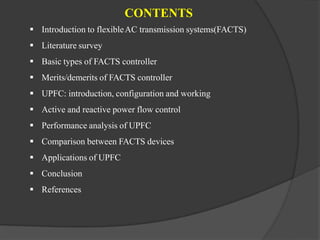
Firstly, I studied the introduction to FACTS technology, their conventional method and modern
technology and basic operation of it. Then studied the various techniques to improve reactive
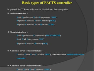
power. There are many FACTS controllers such as Fixed Capacitor-Thyristor Controlled
Reactor (FC-TCR), Static synchronous compensator (STATCOM), Thyristor controlled Series
Capacitor (TCSC), Static synchronous Series Compensator (SSSC) and Unified Power Flow
Controller (UPFC) for power system stability enhancement and improvement of power transfer
capability.
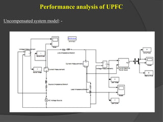
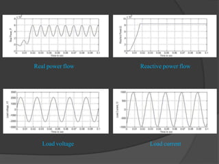
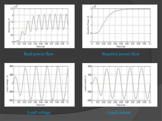
So, I have studied, how power flow control and system stability is improved using UPFC and
studied the uncompensated system model, compensated system model & waveforms which are
done in MATLAB/SIMULINK environment.
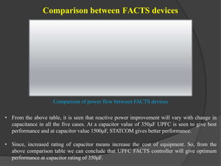
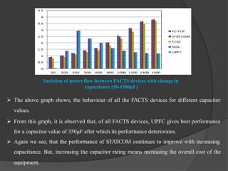
And then compare with other FACTS controller with respect to variation in power flow with
change in capacitance.
So, I can conclude that there are numerous equipments which are capable for power flow
control but there is only one which can control the power flow optimally is UPFC.[1-5]](https://image.slidesharecdn.com/bhagirathsaminarppt-230114121431-3eda655e/85/REACTIVE-POWER-COMPENSATION-ppt-pptx-4-320.jpg)