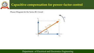
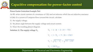
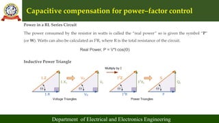
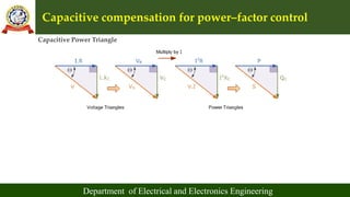
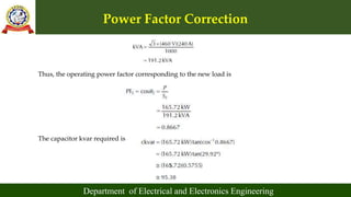
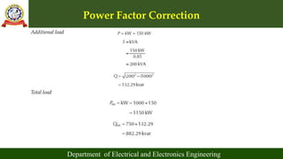
Capacitive compensation for power–factor control
Different types of power capacitors
shunt and series capacitors
Effect of shunt capacitors (Fixed and switched)
Power factor correction
Capacitor allocation
Economic justification
Procedure to determine the best capacitor location.
Nowadays, it is very important to maintain voltage level. Controlling of that voltage is also important. This Presentation contains methods of voltage control.
Introduction to reactive power control in electrical powerDr.Raja R
Introduction to reactive power control in electrical power
Reactive power in transmission line :
Reactive power control
Reactive power and its importance
Apparent Power
Reactive Power
Apparent Power
Reactive Power Formula
this is useful for peoples interested in power quality problems and their mitigation. it provides causes, effects of voltage sag and their mitigation techniques.
This presentation is brief introduction to the transient disturbances(how they occur and reason behind that) and its classification(Oscillatory and Impulsive).
Reactive Power Compensation in 132kv & 33kv Grid of Narsinghpur Areaijceronline
Power Sector is considered to be very important and priority sector as it leads to overall development of country. The cost of installation of new generating units is rising; hence generated electrical energy has to be utilized carefully and efficiently, which changes through each AC cycle. It is proposed to study the effect of group shunt compensation provided for the mix of rural and urban loads, catered from grid sub-stations in the district of Narsinghpur, to assess its adequacy and saving in transmission losses. An optimum combination of compensators which yields maximum benefits in the system shall be worked out. Load Flow Study for the effect of group shunt compensation provided on 132KV bus of 220KV sub-station Narsinghpur and on 33KV buses of 132KV sub stations Srinagar, Narsinghpur, Gadarwara and Burman sub-stations for the mix of rural and urban loads, catered from partial grid network in Narsinghpur district. If reactive power is supplied near the load, the line current can be reduced or minimized, reducing power losses and improving voltage regulation at the load terminals. The leading current drawn by the shunt capacitors compensates the lagging current drawn by the load. The selection of shunt capacitors depends on many factors, the most important of which is the amount of lagging reactive power taken by the load. Objective was to study the effect of group shunt compensation provided for the mix of rural and urban loads, catered from grid sub-stations in the district of Narsinghpur and to assess the adequacy and saving in transmission losses & to work out an optimum combination of compensators which yields maximum benefits in the system. Depending on the stages of 'ON' and 'OFF', operations to be carried out in various permutations and combinations of shunt compensators i.e. switchable capacitor banks provided on 132 KV bus of 220KV substation Narsinghpur and on 33KV buses of 132 KV substations
Application of Capacitors to Distribution System and Voltage RegulationAmeen San
Application of Capacitors to
Distribution System and Voltage
Regulation
POWER FACTOR IMPROVEMENT,
System Harmonics
Voltage Regulation
Methods of Voltage Control
Micro-controller based Automatic Power Factor Correction System ReportTheory to Practical
This project report represents one of the most effective automatic power factor improvements by using static capacitors which will be controlled by a Microcontroller with very low cost although many existing systems are present which are expensive and difficult to manufacture. In this study, many small rating capacitors are connected in parallel and a reference power factor is set as standard value into the microcontroller IC. Suitable number of static capacitors is automatically connected according to the instruction of the microcontroller to improve the power factor close to unity. Some tricks such as using resistors instead of potential transformer and using one of the most low cost microcontroller IC (ATmega8) which also reduce programming complexity that make it one of the most economical system than any other controlling system.
it is the knowledge of the electrical circuit 2 that will help us to update our knowledge and encourage the student to gather the knowledge and upgrade themselves
Soft power factor modification using staticchodachude
A good power quality at a system can optimize the efficiency of electrical energy utilization.
Comparison of active power and apparent power will produce a power factor (COS ø).Capacitors bank can
maintain optimum power factor with compensating some reactive power to the system. Static VAR
Compensator (SVC) is generally composed of a conventional capacitor bank in parallel with the load contactor
switch. This leads to a very large inrush current to the capacitor which will resulting damage to the
contactor switches and also capacitors. To reduce inrush current, thyristor is used as a replacement of
contactor switch. Switch can be set by adjusting the firing angle of thyristor. Power factor improvement consists
of a voltage sensor, current sensor, zero crossing detector, thyristor driver and the capacitor bank. The existing
load on the system consists of induction motor 125W, rectifier with load of series of incandescent lamp with
ballasts 85W and fluorescent lamp 20W.Cos phi variation of the load is 0.49 (lag), 0.99 (lag), 0.92 (lag) and 0.62
(lag) when all the loads connect to the system. Through the calculation, the value of capacitor that can
compensate the reactive power to the system is 5.12 µF, 2.71 µF, 2.41 µF and 9.55µF. The capacitor
installation obtain good response because it can increase the cos phi of system to 0.99 (lag) and the current
consumption of the system is smaller than the pre-installation of capacitors, which can reduce the line system
current up to 30% of the system current
Power Factor Correction Methods
Fixed Capcitors
Synchronous Condensors
Phase Advancers
Switch Capacitors
Static Var Compensator(SVC)
Static Synchronous Compensator(STATCOM)
Modulated power filter capacitor compensator
Economics of power factor improvement
Economical comparison of increasing the power supply
A High Performance PWM Voltage Source Inverter Used for VAR Compensation and ...IJMER
International Journal of Modern Engineering Research (IJMER) is Peer reviewed, online Journal. It serves as an international archival forum of scholarly research related to engineering and science education.
Reactive Power Compensation and Control via Shunt Reactors and Under Ground P...IJERA Editor
In this paper we will cover the techniques used locally to accomplish the reactive power compensation. First, the importance of reactive power compensation is explained through defining the different types of electrical power and showing the effect of power compensation on the electric power network quality. The power under ground cable is the first technique used to compensate for the inductance of overhead transmission lines and power transformers during heavy loading of the network. Then, we explore the application of the two types of shunt reactors in different locations of the network to compensate for the capacitance of the network during light loading. Finally, a conclusion is presented.
Introduction to distribution systems,
Load modeling and characteristics
Coincidence factor
Contribution factor loss factor
Relationship between the load factor and loss factor
Classification of loads (Residential, commercial, Agricultural and Industrial) and their characteristics.
Voltage drop and power–loss calculations:
Derivation for voltage drop and power loss in lines
Uniformly distributed loads and non-uniformly distributed loads
Numerical problems
Three phase balanced primary lines
EDS Unit 4 (Protection and Coordination).pptxDr. Rohit Babu
Protection:
Objectives of distribution system protection
Types of common faults and procedure for fault calculations
Protective devices: Principle of operation of fuses Circuit reclosures
Line sectionalizes and circuit breakers.
Coordination:
Coordination of protective devices: General coordination procedure
Residual current circuit breaker RCCB (Wikipedia).
Voltage drop and power–loss calculations:
Derivation for voltage drop and power loss in lines
Uniformly distributed loads and non-uniformly distributed loads
Numerical problems
Three phase balanced primary lines
PROTECTION AGAINST OVER VOLTAGE AND GROUNDING Part 2Dr. Rohit Babu
Grounded and ungrounded neutral systems
Effects of ungrounded neutral on system performance
Methods of neutral grounding
Solid
Resistance
Reactance
Arcing grounds and grounding Practices
PROTECTION AGAINST OVER VOLTAGE AND GROUNDING Part 1Dr. Rohit Babu
Generation of overvoltages in power systems
Protection against lightning overvoltages
Valve type and zinc oxide lightning arresters
Insulation coordination
BIL
Impulse ratio
Standard impulse test wave
Volt-time characteristics
Grounded and ungrounded neutral systems
Effects of ungrounded neutral on system performance
Methods of neutral grounding
Solid
Resistance
Reactance
Arcing grounds and grounding Practices
PROTECTION AGAINST OVER VOLTAGE AND GROUNDINGDr. Rohit Babu
Generation of overvoltages in power systems
Protection against lightning overvoltages
Valve type and zinc oxide lightning arresters
Insulation coordination
BIL
Impulse ratio
Standard impulse test wave
Volt-time characteristics
Grounded and ungrounded neutral systems
Effects of ungrounded neutral on system performance
Methods of neutral grounding
Solid
Resistance
Reactance
Arcing grounds and grounding Practices
Protection of lines
Overcurrent Protection schemes
PSM, TMS
Numerical examples
Carrier current and three-zone distance relay using impedance relays
Protection of bus bars by using Differential protection
Generator and Transformer Protection (PART 1)Dr. Rohit Babu
Part 1. Generator Protection
Protection of generators against stator faults
Rotor faults and abnormal conditions
Restricted earth fault and inter-turn fault protection
Numerical examples
Relays classification–Instantaneous– DMT and IDMT types– Applications of relays: Over current and under voltage relays– Directional relays– Differential relays and percentage differential relays
Hybrid optimization of pumped hydro system and solar- Engr. Abdul-Azeez.pdffxintegritypublishin
Advancements in technology unveil a myriad of electrical and electronic breakthroughs geared towards efficiently harnessing limited resources to meet human energy demands. The optimization of hybrid solar PV panels and pumped hydro energy supply systems plays a pivotal role in utilizing natural resources effectively. This initiative not only benefits humanity but also fosters environmental sustainability. The study investigated the design optimization of these hybrid systems, focusing on understanding solar radiation patterns, identifying geographical influences on solar radiation, formulating a mathematical model for system optimization, and determining the optimal configuration of PV panels and pumped hydro storage. Through a comparative analysis approach and eight weeks of data collection, the study addressed key research questions related to solar radiation patterns and optimal system design. The findings highlighted regions with heightened solar radiation levels, showcasing substantial potential for power generation and emphasizing the system's efficiency. Optimizing system design significantly boosted power generation, promoted renewable energy utilization, and enhanced energy storage capacity. The study underscored the benefits of optimizing hybrid solar PV panels and pumped hydro energy supply systems for sustainable energy usage. Optimizing the design of solar PV panels and pumped hydro energy supply systems as examined across diverse climatic conditions in a developing country, not only enhances power generation but also improves the integration of renewable energy sources and boosts energy storage capacities, particularly beneficial for less economically prosperous regions. Additionally, the study provides valuable insights for advancing energy research in economically viable areas. Recommendations included conducting site-specific assessments, utilizing advanced modeling tools, implementing regular maintenance protocols, and enhancing communication among system components.
Final project report on grocery store management system..pdfKamal Acharya
In today’s fast-changing business environment, it’s extremely important to be able to respond to client needs in the most effective and timely manner. If your customers wish to see your business online and have instant access to your products or services.
Online Grocery Store is an e-commerce website, which retails various grocery products. This project allows viewing various products available enables registered users to purchase desired products instantly using Paytm, UPI payment processor (Instant Pay) and also can place order by using Cash on Delivery (Pay Later) option. This project provides an easy access to Administrators and Managers to view orders placed using Pay Later and Instant Pay options.
In order to develop an e-commerce website, a number of Technologies must be studied and understood. These include multi-tiered architecture, server and client-side scripting techniques, implementation technologies, programming language (such as PHP, HTML, CSS, JavaScript) and MySQL relational databases. This is a project with the objective to develop a basic website where a consumer is provided with a shopping cart website and also to know about the technologies used to develop such a website.
This document will discuss each of the underlying technologies to create and implement an e- commerce website.
Sachpazis:Terzaghi Bearing Capacity Estimation in simple terms with Calculati...Dr.Costas Sachpazis
Terzaghi's soil bearing capacity theory, developed by Karl Terzaghi, is a fundamental principle in geotechnical engineering used to determine the bearing capacity of shallow foundations. This theory provides a method to calculate the ultimate bearing capacity of soil, which is the maximum load per unit area that the soil can support without undergoing shear failure. The Calculation HTML Code included.
NO1 Uk best vashikaran specialist in delhi vashikaran baba near me online vas...Amil Baba Dawood bangali
Contact with Dawood Bhai Just call on +92322-6382012 and we'll help you. We'll solve all your problems within 12 to 24 hours and with 101% guarantee and with astrology systematic. If you want to take any personal or professional advice then also you can call us on +92322-6382012 , ONLINE LOVE PROBLEM & Other all types of Daily Life Problem's.Then CALL or WHATSAPP us on +92322-6382012 and Get all these problems solutions here by Amil Baba DAWOOD BANGALI
#vashikaranspecialist #astrologer #palmistry #amliyaat #taweez #manpasandshadi #horoscope #spiritual #lovelife #lovespell #marriagespell#aamilbabainpakistan #amilbabainkarachi #powerfullblackmagicspell #kalajadumantarspecialist #realamilbaba #AmilbabainPakistan #astrologerincanada #astrologerindubai #lovespellsmaster #kalajaduspecialist #lovespellsthatwork #aamilbabainlahore#blackmagicformarriage #aamilbaba #kalajadu #kalailam #taweez #wazifaexpert #jadumantar #vashikaranspecialist #astrologer #palmistry #amliyaat #taweez #manpasandshadi #horoscope #spiritual #lovelife #lovespell #marriagespell#aamilbabainpakistan #amilbabainkarachi #powerfullblackmagicspell #kalajadumantarspecialist #realamilbaba #AmilbabainPakistan #astrologerincanada #astrologerindubai #lovespellsmaster #kalajaduspecialist #lovespellsthatwork #aamilbabainlahore #blackmagicforlove #blackmagicformarriage #aamilbaba #kalajadu #kalailam #taweez #wazifaexpert #jadumantar #vashikaranspecialist #astrologer #palmistry #amliyaat #taweez #manpasandshadi #horoscope #spiritual #lovelife #lovespell #marriagespell#aamilbabainpakistan #amilbabainkarachi #powerfullblackmagicspell #kalajadumantarspecialist #realamilbaba #AmilbabainPakistan #astrologerincanada #astrologerindubai #lovespellsmaster #kalajaduspecialist #lovespellsthatwork #aamilbabainlahore #Amilbabainuk #amilbabainspain #amilbabaindubai #Amilbabainnorway #amilbabainkrachi #amilbabainlahore #amilbabaingujranwalan #amilbabainislamabad
Saudi Arabia stands as a titan in the global energy landscape, renowned for its abundant oil and gas resources. It's the largest exporter of petroleum and holds some of the world's most significant reserves. Let's delve into the top 10 oil and gas projects shaping Saudi Arabia's energy future in 2024.
About
Indigenized remote control interface card suitable for MAFI system CCR equipment. Compatible for IDM8000 CCR. Backplane mounted serial and TCP/Ethernet communication module for CCR remote access. IDM 8000 CCR remote control on serial and TCP protocol.
• Remote control: Parallel or serial interface.
• Compatible with MAFI CCR system.
• Compatible with IDM8000 CCR.
• Compatible with Backplane mount serial communication.
• Compatible with commercial and Defence aviation CCR system.
• Remote control system for accessing CCR and allied system over serial or TCP.
• Indigenized local Support/presence in India.
• Easy in configuration using DIP switches.
Technical Specifications
Indigenized remote control interface card suitable for MAFI system CCR equipment. Compatible for IDM8000 CCR. Backplane mounted serial and TCP/Ethernet communication module for CCR remote access. IDM 8000 CCR remote control on serial and TCP protocol.
Key Features
Indigenized remote control interface card suitable for MAFI system CCR equipment. Compatible for IDM8000 CCR. Backplane mounted serial and TCP/Ethernet communication module for CCR remote access. IDM 8000 CCR remote control on serial and TCP protocol.
• Remote control: Parallel or serial interface
• Compatible with MAFI CCR system
• Copatiable with IDM8000 CCR
• Compatible with Backplane mount serial communication.
• Compatible with commercial and Defence aviation CCR system.
• Remote control system for accessing CCR and allied system over serial or TCP.
• Indigenized local Support/presence in India.
Application
• Remote control: Parallel or serial interface.
• Compatible with MAFI CCR system.
• Compatible with IDM8000 CCR.
• Compatible with Backplane mount serial communication.
• Compatible with commercial and Defence aviation CCR system.
• Remote control system for accessing CCR and allied system over serial or TCP.
• Indigenized local Support/presence in India.
• Easy in configuration using DIP switches.
RAT: Retrieval Augmented Thoughts Elicit Context-Aware Reasoning in Long-Hori...
EDS Unit 5.pptx
1. LENDI INSTITUTE OF ENGINEERING AND TECHNOLOGY
Jonnada, Andhra Pradesh- 535005
UNIT–V: Compensation for Power
Factor Improvement
Department of Electrical and Electronics Engineering
2. Syllabus
Department of Electrical and Electronics Engineering
Capacitive compensation for power–factor control
Different types of power capacitors
shunt and series capacitors
Effect of shunt capacitors (Fixed and switched)
Power factor correction
Capacitor allocation
Economic justification
Procedure to determine the best capacitor location.
3. Capacitive compensation for power–factor control
Department of Electrical and Electronics Engineering
Power Factor Correction (Power Factor Compensation) uses parallel connected capacitors to oppose
the effects of inductive elements and reduce the phase shift between the voltage and current
Power Factor Correction is a technique which uses capacitors to reduce the reactive power
component of an AC circuit in order to improve its efficiency and reduce current.
When dealing with direct current (DC) circuits, the power dissipated by the connected load is
simply calculated as the product of the DC voltage times the DC current, that is V*I, given in watts
(W).
For a fixed resistive load, current is proportional to the applied voltage so the electrical power
dissipated by the resistive load will be linear.
For an AC circuit, the power dissipated in watts at any instant in time is equal to the product of the
volts and amperes at that exact same instant.
4. Capacitive compensation for power–factor control
Department of Electrical and Electronics Engineering
In a DC circuit the average power is simply V*I, but the average power of an AC circuit is not the same
value as many AC loads have inductive elements, such as coils, windings, transformers, etc. where the
current is out of phase with the voltage by some degrees resulting in the actual power dissipated in
watts being less than the product of the voltage and current.
For an AC circuit containing an inductor, coil, or solenoid or some other form of inductive load, its
inductive reactance (XL) creates a phase angle with the current lagging behind the voltage by 90o.
5. Capacitive compensation for power–factor control
Department of Electrical and Electronics Engineering
RL Series Circuit R and L Vector Diagrams
6. Capacitive compensation for power–factor control
Department of Electrical and Electronics Engineering
Phasor Diagram for the Series RL Circuit
7. Capacitive compensation for power–factor control
Department of Electrical and Electronics Engineering
Power Factor Correction Example No1
An RL series circuit consists of a resistance of 15Ω and an inductor which has an inductive reactance
of 26Ω. If a current of 5 amperes flows around the circuit, calculate:
1) the supply voltage.
2) the phase angle between the supply voltage and circuit current.
3) Draw the resulting phasor diagram.
Solution: 1). The supply voltage VS
8. Capacitive compensation for power–factor control
Department of Electrical and Electronics Engineering
We can double check this answer of 150Vrms using the impedances of the circuit as follows:
2). The phase angle (phi) using Trigonometry functions is:
9. Capacitive compensation for power–factor control
Department of Electrical and Electronics Engineering
3). The resulting phasor diagram showing VS
10. Capacitive compensation for power–factor control
Department of Electrical and Electronics Engineering
Power in a RL Series Circuit
The power consumed by the resistor in watts is called the “real power” so is given the symbol “P”
(or W). Watts can also be calculated as I2R, where R is the total resistance of the circuit.
Real Power, P = V*I cos(Θ)
Inductive Power Triangle
11. Capacitive compensation for power–factor control
Department of Electrical and Electronics Engineering
Capacitive Power Triangle
12. Capacitive compensation for power–factor control
Department of Electrical and Electronics Engineering
Power Triangle Equations
13. Capacitive compensation for power–factor control
Department of Electrical and Electronics Engineering
Power Factor Correction Example No. 2
A coil has a resistance of 10Ω and an inductance of 46mH. If it draws a current of 5 Amperes when
connected to a 100Vrms, 60Hz supply, calculate:
1) the voltages across the components.
2) the phase angle of the circuit.
3) the different powers consumed by the series RL circuit.
14. Capacitive compensation for power–factor control
Department of Electrical and Electronics Engineering
First find the impedances
1). The voltages across the resistor, VR and inductor, VL
15. Capacitive compensation for power–factor control
Department of Electrical and Electronics Engineering
2). The phase angle of the circuit
3). The circuit power
16. Capacitive compensation for power–factor control
Department of Electrical and Electronics Engineering
Power Factor Correction
• Power Factor Correction (Power Factor Compensation) improves the phase angle between the supply
voltage and current while the real power consumption in watts remains the same.
• Adding an impedance in the form of capacitive reactance in parallel with the coil above will
decrease Θ and thus increases the power factor which in turn reduces the circuits rms current
drawn from the supply.
• The power factor of an AC circuit can vary from between 0 and 1 depending on the strength of the
inductive load but in reality it can never be less than about 0.2 for the heaviest of inductive loads.
• Adding a capacitor in parallel with the coil will not only reduce this unwanted reactive power, but
will also reduce the total amount of current taken from the source supply.
17. Capacitive compensation for power–factor control
Department of Electrical and Electronics Engineering
A power factor of 0.95 is equal to a phase angle of: cos(0.95) = 18.2o thus the amount of VAR required
is:
If the original uncorrected VAR value was 433VAR and the new calculated value is 82.2VAR, we need
a reduction of 433 – 82.2 = 350.8 VAR(capacitive).
Therefore:
18. Capacitive compensation for power–factor control
Department of Electrical and Electronics Engineering
Therefore the capacitance of the capacitor is calculated as:
So to improve the power factor of the coil in example no2 from 0.5 to 0.95 requires a parallel
connected capacitor of 93uF.
New Volt-Amperes Value
19. Capacitive compensation for power–factor control
Department of Electrical and Electronics Engineering
Power Triangle
If the circuits apparent power has been reduced from 500VA to just 263VA, we can calculate the rms
current supplied as:
S = V*I, therefore: I = S/V = 263/100 = 2.63 Amperes
20. Capacitive compensation for power–factor control
Department of Electrical and Electronics Engineering
Final Power Factor Correction Circuit
This has the effect of reducing the circuits power factor, that is the ratio of active power to the
apparent power, as well as improving the power quality of the circuit and reduces the amount of
source current required. This technique is called “Power Factor Correction”.
21. ADVANTAGES AND BENEFITS OF POWER FACTOR IMPROVEMENT
Department of Electrical and Electronics Engineering
(i) The cost and bill for the energy is reduced since there is penalty for poor power factor (<0.85)
(ii) Voltage improvement and better regulation
(iii) Overall system losses becomes reduced and hence is important from conservation of energy
Table 1: Typical power factor values of industrial loads and plants
22. Different types of power capacitors
Department of Electrical and Electronics Engineering
• A power capacitor is a highly technical and complex device in that very thin dielectric materials
and high electric stresses are involved, coupled with highly sophisticated processing techniques.
• In the past, most power capacitors were constructed with two sheets of pure aluminum foil
separated by three or more layers of chemically impregnated kraft paper.
• Capacitor sizes have increased from the 15–25 kvar range to the 200–300 kvar range (capacitor
banks are usually supplied in sizes ranging from 300 to 1800 kvar).
• Capacitors are getting more attention today than ever before, partly due to a new dimension
added in the analysis: changeout economics.
• Under certain circumstances, even replacement of older capacitors can be justified on the basis of
lower-loss evaluations of the modern capacitor design.
23. Different types of power capacitors
Department of Electrical and Electronics Engineering
Power capacitors are passive electronic components that provide
a static source of reactive power in electrical distribution systems.
Capacitance, a measure of energy storage ability, is typically
expressed as
C = K A/D,
where A is the area of the electrodes, D is their separation,
and K is a function of the dielectric between the electrodes.
Power capacitors are used in:
•the aerospace and automotive industries
•power factor correction and lighting circuits
•power supplies
•motor starters
24. Different types of power capacitors
Department of Electrical and Electronics Engineering
1. Aluminum Electrolytic Capacitors: Aluminum electrolytic capacitors use an electrolytic process
to form the dielectric. Wet electrolytic capacitors have a moist electrolyte. Dry or solid electrolytic
capacitors do not.
2. Ceramic Capacitors: Ceramic capacitors have a dielectric made of ceramic materials.
3. Chip Capacitors: Chip capacitors or surface mount capacitors do not have leads.
4. Film Capacitors: Film capacitors are insulated with polyester, polycarbonate, polypropylene,
polystyrene, or other dielectric materials.
5. High Voltage Capacitors: High voltage capacitors are used for storing charge and energy in high
voltage applications.
6. Supercapacitors: Ultracapacitors store charges (energy) by physically separating positive and
negative charges (unlike batteries which do so chemically). Very high power densities can be
achieved by this method.
25. Different types of power capacitors
Department of Electrical and Electronics Engineering
7. Tantalum Capacitors: Tantalum capacitors are used in smaller electronic devices
including portable telephones, pagers, personal computers, and automotive electronics.
26. Shunt and Series capacitors
Department of Electrical and Electronics Engineering
1. Series Capacitors
Series capacitors, that is, capacitors connected in
series with lines, have been used to a very limited
extent on distribution circuits due to being a
more specialized type of apparatus with a limited
range of application.
Fig. 1: Voltage phasor diagrams for a feeder circuit of
lagging power factor: (a) and (c) without and (b) and (d)
with series capacitors.
• A series capacitor is a negative (capacitive)
reactance in series with the circuit’s positive
(inductive) reactance with the effect of
compensating for part or all of it.
27. Shunt and Series capacitors
Department of Electrical and Electronics Engineering
• A series capacitor can even be considered as a voltage regulator that provides for a voltage boost
that is proportional to the magnitude and power factor of the through current.
• A series capacitor produces more net voltage rise than a shunt capacitor at lower power factors,
which creates more voltage drop.
28. Shunt and Series capacitors
Department of Electrical and Electronics Engineering
Fig. 1: Voltage phasor diagrams for a feeder circuit of lagging power
factor: (a) and (c) without and (b) and (d) with series capacitors.
Consider the feeder circuit and its
voltage phasor diagram as shown in
Figure 1 (a) and (c).
The voltage drop through the feeder can
be expressed approximately as
cos sin
L
VD IR IX
(1)
where
R is the resistance of the feeder circuit
XL is the inductive reactance of the feeder
circuit
cos θ is the receiving-end power factor
sin θ is the sine of the receiving-end power
factor angle
29. Shunt and Series capacitors
Department of Electrical and Electronics Engineering
However, when a series capacitor is applied, as shown in Figure 1 (b) and (d), the resultant lower
voltage drop can be calculated as
cos ( )sin
L C
VD IR I X X
(2)
where Xc is the capacitive reactance of the series capacitor.
1.1 Overcompensation
The series-capacitor size is selected for a distribution feeder application in such a way that the
resultant capacitive reactance is smaller than the inductive reactance of the feeder circuit.
However, in certain applications (where the resistance of the feeder circuit is larger than its inductive
reactance), the reverse might be preferred so that the resultant voltage drop is
cos ( )sin
C L
VD IR I X X
(3)
The resultant condition is known as overcompensation.
30. Shunt and Series capacitors
Department of Electrical and Electronics Engineering
Fig. 2 Overcompensation of the receiving-end voltage: (a) at
normal load and (b) at the start of a large motor.
31. Shunt and Series capacitors
Department of Electrical and Electronics Engineering
1.2 Leading Power Factor
To decrease the voltage drop considerably between the sending and receiving ends by the application
of a series capacitor, the load current must have a lagging power factor.
Fig. 3 Voltage phasor diagram with leading power factor: (a)
without series capacitors and (b) with series capacitors.
As can be seen from the figure, the receiving
end voltage is reduced as a result of having
series capacitors.
When cos θ = 1.0, sin θ ≅ 0, and therefore,
( )sin 0
L C
I X X
hence, Equation (2) becomes
VD IR
(4)
Thus, in such applications, series capacitors practically have no value.
32. Shunt and Series capacitors
Department of Electrical and Electronics Engineering
2. Shunt Capacitors
• Shunt capacitors, that is,
capacitors connected in
parallel with lines, are used
extensively in distribution
systems.
• Shunt capacitors supply the
type of reactive power or
current to counteract the out
of- phase component of
current required by an
inductive load. Fig. 4 Voltage phasor diagrams for a feeder circuit of lagging power
factor: (a) and (c) without and (b) and (d) with shunt capacitors.
33. Shunt and Series capacitors
Department of Electrical and Electronics Engineering
Voltage drop in feeders, or in short transmission lines, with lagging power factor can be
approximated as
R X L
VD I R I X
(5)
where
R is the total resistance of the feeder circuit, Ω
XL is the total inductive reactance of the feeder circuit, Ω
IR is the real power (or in-phase) component of the current, A
IX is the reactive (or out-of-phase) component of the current lagging the voltage by 90°, A
34. Shunt and Series capacitors
Department of Electrical and Electronics Engineering
Voltage drop in feeders, or in short transmission lines, with lagging power factor can be
approximated as
R X L
VD I R I X
(5)
where
R is the total resistance of the feeder circuit, Ω
XL is the total inductive reactance of the feeder circuit, Ω
IR is the real power (or in-phase) component of the current, A
IX is the reactive (or out-of-phase) component of the current lagging the voltage by 90°, A
35. Shunt and Series capacitors
Department of Electrical and Electronics Engineering
Voltage drop in feeders, or in short transmission lines, with lagging power factor can be
approximated as
R X L
VD I R I X
(5)
where
R is the total resistance of the feeder circuit, Ω
XL is the total inductive reactance of the feeder circuit, Ω
IR is the real power (or in-phase) component of the current, A
IX is the reactive (or out-of-phase) component of the current lagging the voltage by 90°, A
36. Shunt and Series capacitors
Department of Electrical and Electronics Engineering
Example 1
Consider the right-angle triangle shown in Figure 5 (b). Determine the power factor of the load on a
460 V three-phase system, if the ammeter reads 100 A and the wattmeter reads 70 kW.
Fig. 5 (a) Phasor diagram and (b) power triangle for a typical
distribution load.
Solution:
3( )( )
1000
V I
S
3(460 )(100 )
1000
V A
79.67 kVA
37. Shunt and Series capacitors
Department of Electrical and Electronics Engineering
Thus,
cos
P
pf
S
70
79.67
kW
kVAR
0.88 88 %
or
38. Effect of shunt capacitors (Fixed and switched)
Department of Electrical and Electronics Engineering
Fixed Capacitor Bank
• There are certain loads mainly certain industrial loads which need fixed reactive power to meet
power factor.
• In this type feeder fixed capacitor bank is used.
• These banks do not have separate control system to switch ON or OFF.
• These banks run with feeders.
• The banks are connected to the feeders as long as the feeders are live.
39. Effect of shunt capacitors (Fixed and switched)
Department of Electrical and Electronics Engineering
Switched Capacitor Banks
• In high voltage power system, compensation of reactive power is mainly required during peak load
condition of system. There may be reverse effect if the bank is connected to the system at mean load
condition.
• At low load condition, the capacitive effect of bank may increase the reactive power of the system
instead of decreasing it.
• In this situation capacitors bank must be switched ON during peak load poor power factor
condition and must also be switched OFF during low load and high power factor condition. Here
switched capacitor banks are used.
40. Power Factor Correction
Department of Electrical and Electronics Engineering
The cosine of the angle between current and sending voltage is known as the power factor of the
circuit.
Assume that a load is supplied with a real power P, lagging reactive power Q1, and apparent power S1
at a lagging power factor of
(1)
or
When a shunt capacitor of Qc kVA is installed at the load, the power factor can be improved from cos θ1
to cos θ2, where
41. Power Factor Correction
Department of Electrical and Electronics Engineering
or
(2)
2.1 Concept of Leading and Lagging Power Factors
In general, for a given load, the power factor
is lagging if the load withdraws reactive
power; on the other hand, it is leading if the
load supplies reactive power.
Fig. 6 Examples of some of the sources of leading
and lagging reactive power at the load.
42. Power Factor Correction
Department of Electrical and Electronics Engineering
2.2 Economic Power Factor
• As can be observed from Figure 7 (b), the apparent power and the reactive power are decreased from S1
to S2 kVA and from Q1 to Q2 kVAR (by providing a reactive power of Q), respectively.
• The reduction of reactive current results in a reduced total current, which in turn causes less power
losses.
Fig. 7 Illustration of power factor correction.
• The economic power factor is the
point at which the economic benefits
of adding shunt capacitors just equal
the cost of the capacitors.
• In the past, this economic power factor was around 95%.
• Today’s high plant and fuel costs have pushed the economic power factor toward unity.
43. Power Factor Correction
Department of Electrical and Electronics Engineering
Example 2
Assume that a substation supplies three different kinds of loads, mainly, incandescent lights, induction motors,
and synchronous motors, as shown in Figure 8. The substation power factor is found from the total reactive and
real powers of the various loads that are connected. Based on the given data in Figure 8, determine the following:
a. The apparent, real, and kVARs of each load
b. The total apparent, real, and reactive powers of the power that should be supplied by the substation
c. The total power factor of the substation
Fig. 8: For Example 8.2: (a)
connection diagram, (b) phasor
diagrams of individual loads,
and (c) phasor diagram of
combined loads.
44. Power Factor Correction
Department of Electrical and Electronics Engineering
Solution
a.
1. For a 100 kVA lighting load Since incandescent lights are basically a unity power factor load, it is
assumed that all the current is kilowatt current. Hence,
1 1
100 100
S P
kVA kW
2. For 400 hp of connected induction motor loads
Assume that for the motor loads,
45. Power Factor Correction
Department of Electrical and Electronics Engineering
3. 200 hp motor with a 0.8 leading power factor
At full load, assume kVA = motor-hp rating = 200 kVA:
47. Power Factor Correction
Department of Electrical and Electronics Engineering
c. The kVA of the substation is
The power factor of the substation is
48. Power Factor Correction
Department of Electrical and Electronics Engineering
Example 3
Assume that a load withdraws 80 kW and 60 kvar at a 0.8 power factor. It is required that its power
factor is to be improved from 80% to 90% by using capacitors. Determine the amount of the reactive
power to be provided by using capacitors.
Without capacitors at PF = 0.8
Solutions
kW = 80
kvar = 60
Thus, the kVA requirement of the load is
kVA = (802 + 602)1/2 = 100 kVA
49. Power Factor Correction
Department of Electrical and Electronics Engineering
With capacitors at PF = 0.9
kW = 80
kVA ≅ 88.9
Hence, the line supplies 38.7 kvar and the load needs 60 kvar, and the capacitor supplies the
difference, or
50. Power Factor Correction
Department of Electrical and Electronics Engineering
Example 4
Assume that a certain load withdraws a kilowatt current of 2 A and kilovar current of 2 A. Determine
the amount of total current that it withdraws.
Solution:
(kvar current)^2+ (kW current)^2= (total current)^2
(2 A)^2+ (2 A)^2= (total current)^2
or
4 + 4 = (total current)^2
Hence, Total current = 8^1/2= 2.83 A
51. Power Factor Correction
Department of Electrical and Electronics Engineering
Example 5
Assume that a 460 V cable circuit is rated at 240 A but is carrying a load of 320 A at 0.65 power factor.
Determine the kvar of capacitor that is needed to reduce the current to 240 A.
Solution
The kVA corresponding to 240 A is
52. Power Factor Correction
Department of Electrical and Electronics Engineering
Thus, the operating power factor corresponding to the new load is
The capacitor kvar required is
53. Power Factor Correction
Department of Electrical and Electronics Engineering
Example 6
Assume that a 1000 kW turbine unit (turbogenerator set) has a turbine capability of 1250 kW. It is
operating at a rated load of 1250 kVA at 0.85 power factor. An additional load of 150 kW at 0.85 power
factor is to be added. Determine the value of capacitors needed in order not to overload the turbine nor
the generator.
Solution:
Original load
55. Power Factor Correction
Department of Electrical and Electronics Engineering
The minimum operating power factor for a load of 1150 kW and not exceeding the kVA rating of the
generator is
The maximum load kvar for this situation is
56. Power Factor Correction
Department of Electrical and Electronics Engineering
where 0.426 is the tangent corresponding to the maximum power factor of 0.935.
Thus, the capacitors must provide the difference between the total load kvar and the permissible
generator kvar, or
57. OPTIMUM POWER FACTOR FOR DISTRIBUTION SYSTEMS
Department of Electrical and Electronics Engineering
For a given power Pk the peak power supplied, Qc required capacitor bank kVAR, is obtained by
Where tan is the original p.f and tan the optimum p.f. tan is obtained with the following
procedure.
1
(i) The best desired p.f (a value chosen between 0.90 to 0.98) is set.
(ii) Additional savings in ‘kW’ losses at the set p.f value, when all capacitors are connected to the
substation or distribution bus is determined.
(iii) Reduction in losses due to capacitors applied to substation buses and additional losses due to
capacitors are computed.
(iv) Reduction in KVA demand and hence the additional capacitors needed at buses and feeders is
computed.
58. OPTIMUM POWER FACTOR FOR DISTRIBUTION SYSTEMS
Department of Electrical and Electronics Engineering
v. Total annual savings in demand reduction due to additional capacitors applied, is computed
(Rs/year).
vi. Total annual saving due to additional released capacity per year and hence the annual savings due
to energy losses (Rs/year).
vii. Total annual losses due to cost of capacitors, energy losses in capacitors and other operating
expenses are computed.
viii.Net savings (annual) is arrived at (Rs/year)
ix. Is the power factor set economical? For this, the procedure is repeated by setting a new value.
x. Best p.f is one which gives maximum value for step viii.
59. OPTIMUM POWER FACTOR FOR DISTRIBUTION SYSTEMS
Department of Electrical and Electronics Engineering
1. Best Capacitor Location and Optimum Capacitor Size
The capacitor size and location is usually determined by minimizing (i) power loss (ii) voltage
regulation, and (iii) additional cost and other expenses for illustration.
The procedure usually followed is
(i) to determine the desired p.f for the given load or circuit from the data, viz., kW or KVA and p.f
(ii) the feeder or line voltage and improvement needed
(iii) to determine correction factor needed to correct either load or feeder circuit p.f from the existing
one
(iv) to check the existing capacitors or other p.f correcting devices, their capacity, location, etc., and
improvement given
60. OPTIMUM POWER FACTOR FOR DISTRIBUTION SYSTEMS
Department of Electrical and Electronics Engineering
Optimal Location of Capacitor
• To obtain the best location for the capacitor banks, the feeder line is decided into a number of
sections with a combination of both uniformly distributed loads and concentrated loads.
• This component is counterbalanced by a capacitor bank in each section or segment such that power
loss due to inductive current is reduced by the capacitor allocated in that section.
• The ratio of the reactive (capacitive) ‘kVAR’ of the capacitor to the total reactive load is determined
along with the ratio reactive current at the end of the line segment to the beginning of the line
segment (a).
• The distance of capacitor bank from the feeding point of the line segment is obtained by considering
(a) the ratio, (b) original losses due to reactive current, (c) capacitance, and (d) compensation ratio.
• The optimum number of capacitor banks is obtained by making the cost function of the above
variables a minimum.
61. OPTIMUM POWER FACTOR FOR DISTRIBUTION SYSTEMS
Department of Electrical and Electronics Engineering
2 Benefits with Capacitor Installation in Distribution Systems
In general, the benefits from installation of capacitors are
(i) The generation plant capacity, together with transmission and distribution substations and network
capacity is released and hence increased to that extent
(ii) Reduced energy losses (power losses)
(iii) Reduced voltage drop and improved voltage regulation
(iv) Increase in revenue due to voltage improvement, reduced losses and hence supply of more energy
Quantitative estimate of the above benefit and hence the revenue increase is a more involved procedure and
complex calculations are needed.
The total benefits due to capacitors installation can be put as total financial (benefit) obtained due to (i)
Demand reduction + (ii) Energy savings (reduction) + Revenue increase due to release of additional capacity.
62. OPTIMUM POWER FACTOR FOR DISTRIBUTION SYSTEMS
Department of Electrical and Electronics Engineering
Review Questions
1. Explain the need for p.f improvement in distribution systems.
2. How in the capacitor bank ratings obtained when the load p.f is to be improved from cos theta1 to cos
theta 2?
3. Explain how reduction in line current and hence power losses are obtained with p.f improvement.
4. What are the different locations for p.f improvement capacitors? Discuss their relative advantages and
disadvantages.
5. How does p.f improvement help in reduction in % VD and hence voltage regulation of distribution
transformers? With transformer of 6% reactance and 2% magnetizing current, what will be the probable
ratings of capacitor bank to compensate for magnetizing current and improve regulation by 2%?
6. What is series capacitor compensation in feeder lines ? How does it improve the regulation of the lines?
Discuss with suitable examples.
63. OPTIMUM POWER FACTOR FOR DISTRIBUTION SYSTEMS
Department of Electrical and Electronics Engineering
8. Discuss how voltage profi le of a long feeder can be improved by connecting shunt capacitor
banks at the end of the feeders.
9. How is economical power factor arrived at for a given distribution system with different loads ?
10. What is the justification for p.f improve and what are the benefits ?
11. Compare and explain role of shunt and series capacitors in p.f correction.