Downloaded 444 times


This seminar report discusses power factor improvement using Unified Power Flow Controllers (UPFC), detailing the importance of power factor correction for enhancing the efficiency of power systems. It covers Flexible AC Transmission Systems (FACTS), their objectives, basic types, and the operations of UPFC, which integrates functionalities for controlling real and reactive power flow in transmission systems. The report highlights the growing necessity for effective power quality management due to the rise of electronic devices and their impact on power factor and harmonic distortion.
Presentation on enhancing power factor in electrical systems using UPFC.
Outline of chapters including Introduction, FACTS, UPFC principles, applications, and conclusion.
List of figures illustrating key concepts related to FACTS and UPFC technology.
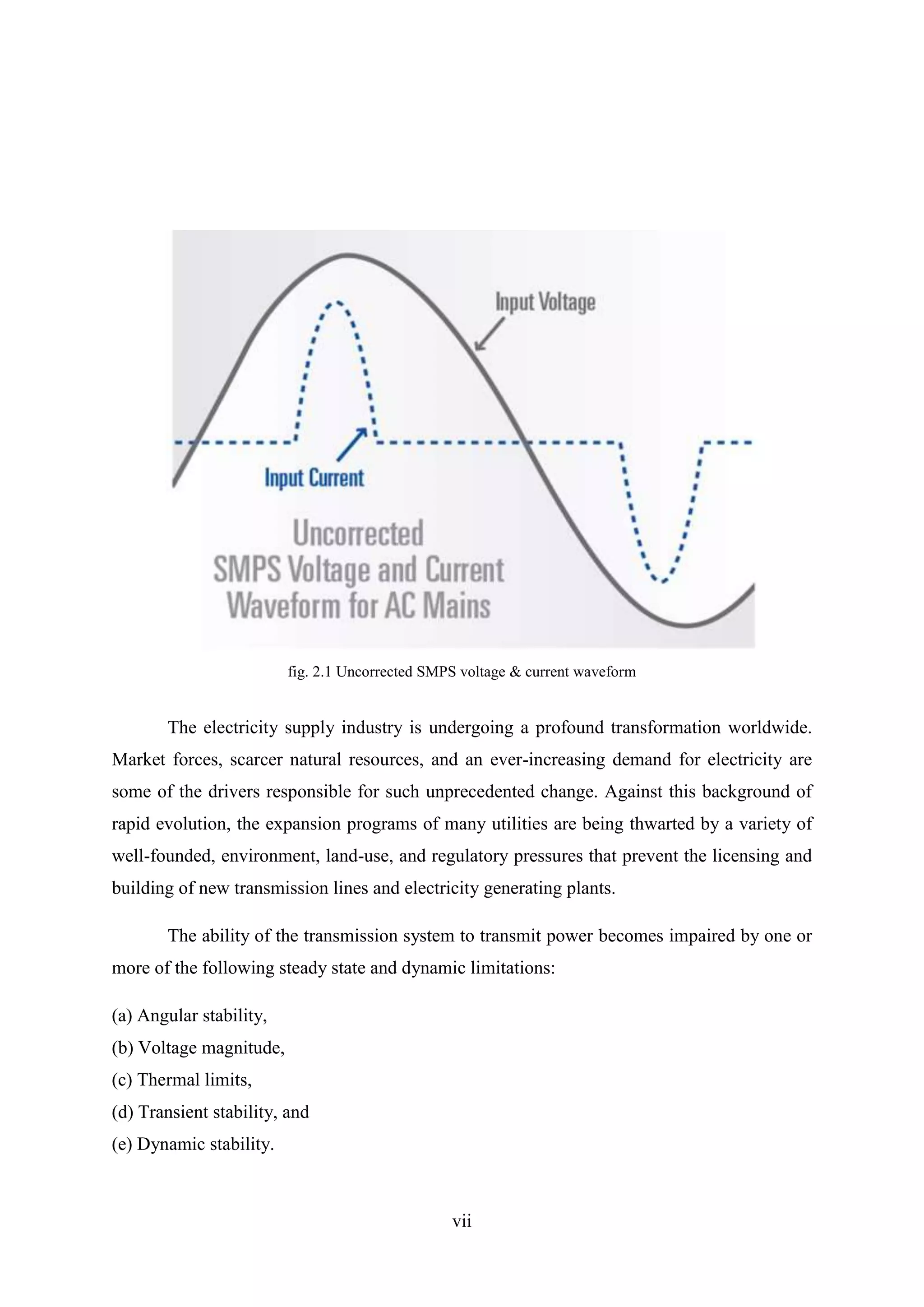
Importance of power factor correction for efficiency in power systems amid rising electronic loads.
Introduction to FACTS systems which enhance AC transmission control and objectives of FACTS Controllers.
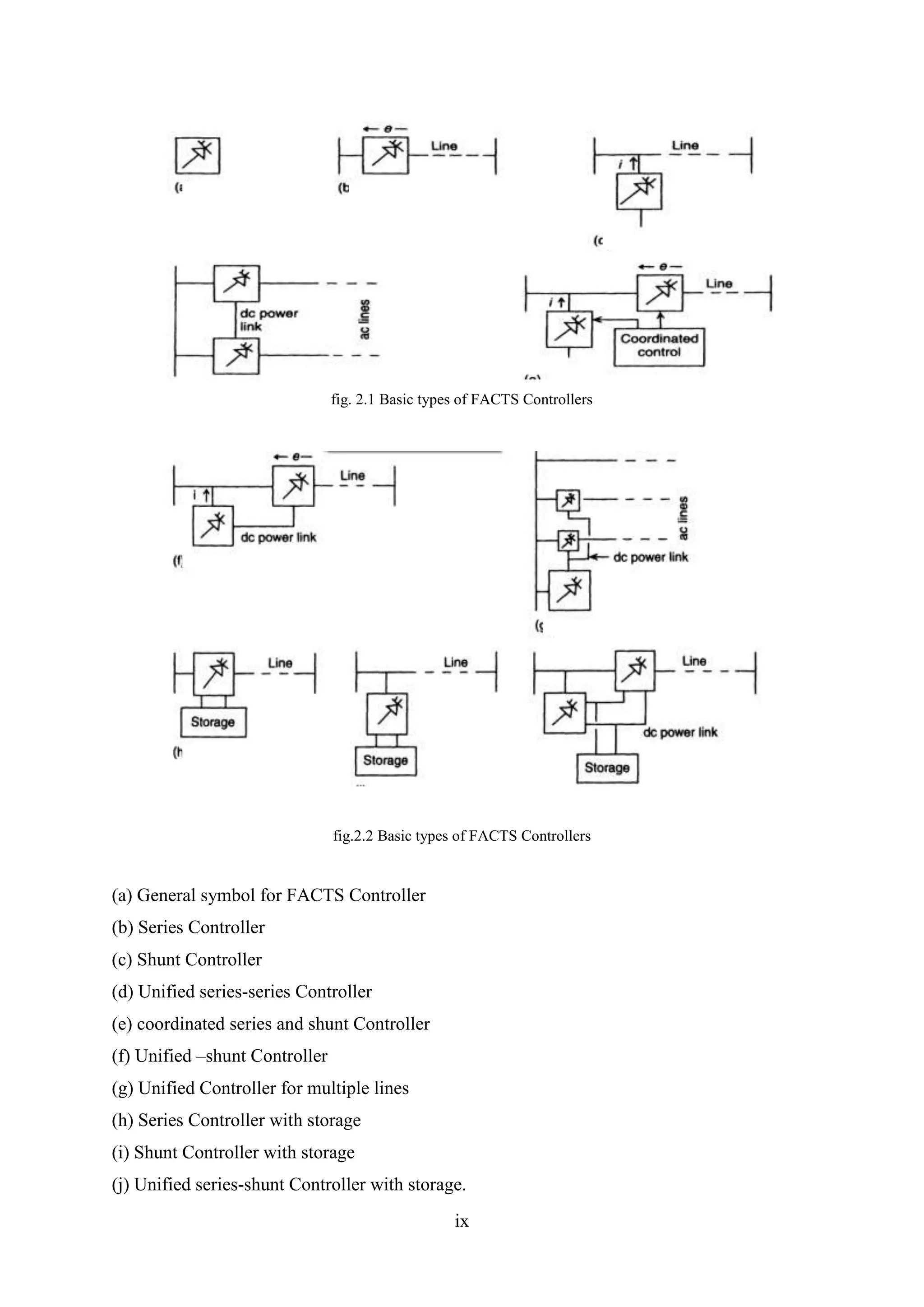
Explains series, shunt, and combined FACTS controllers and their benefits for transmission systems.
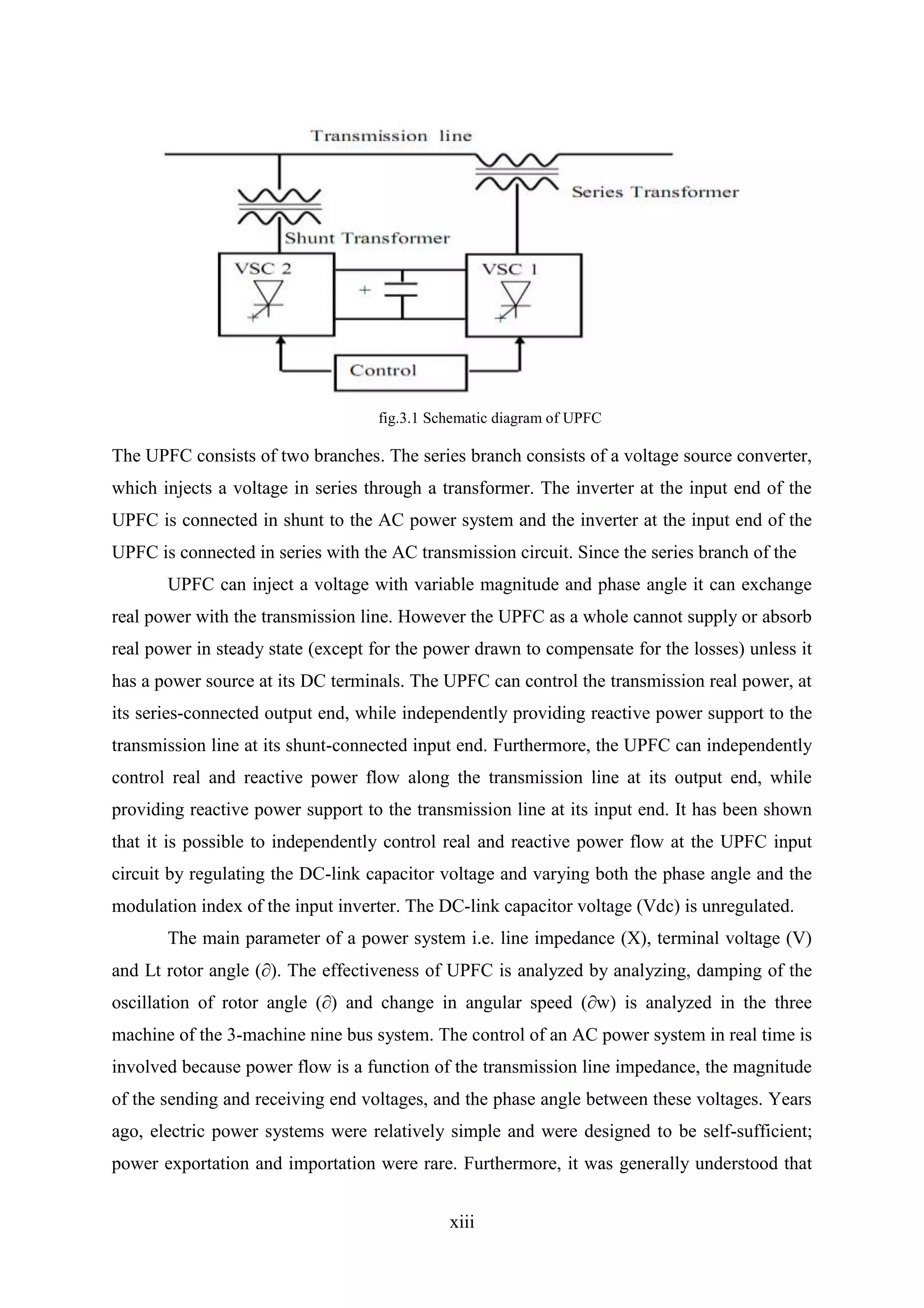
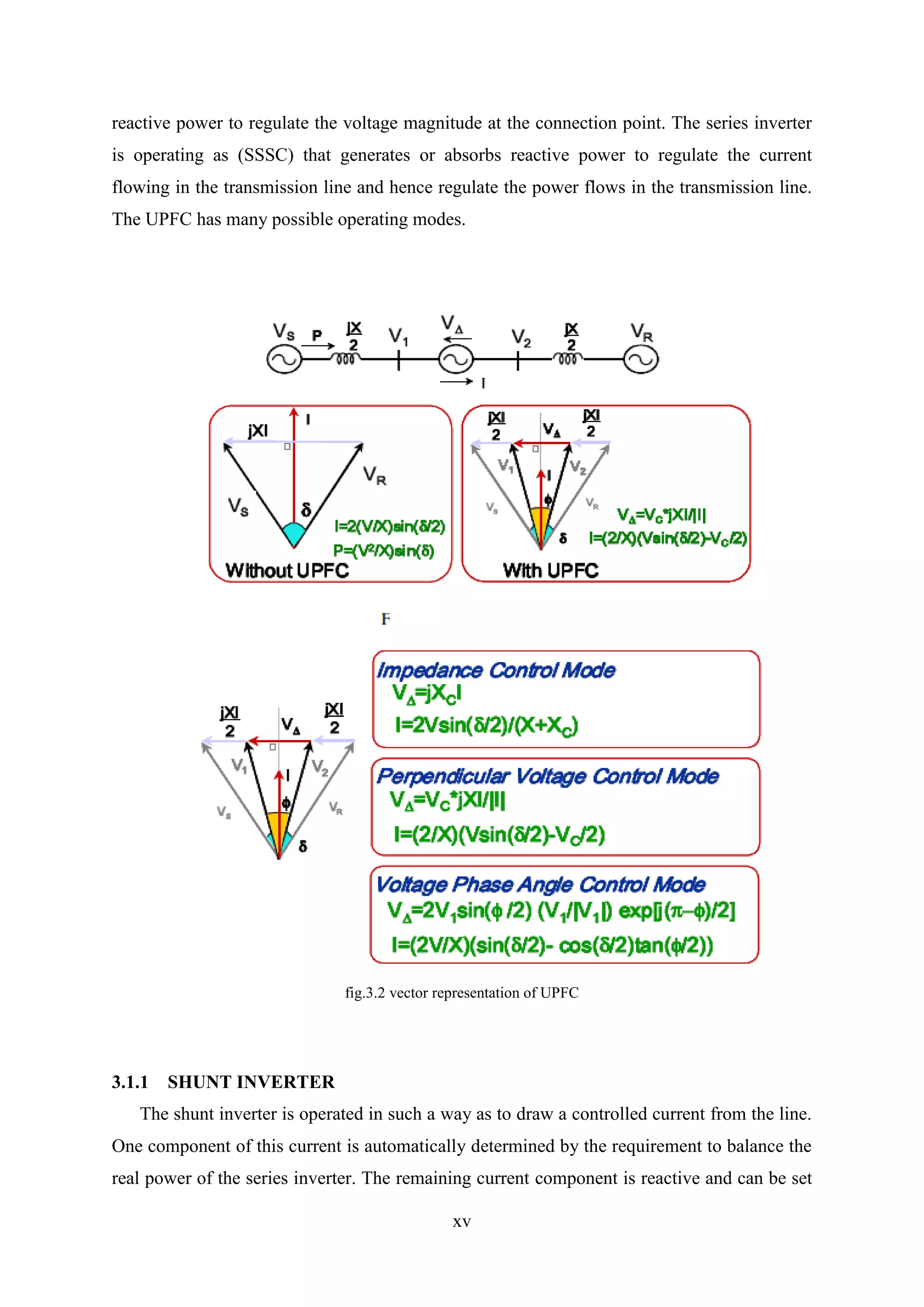
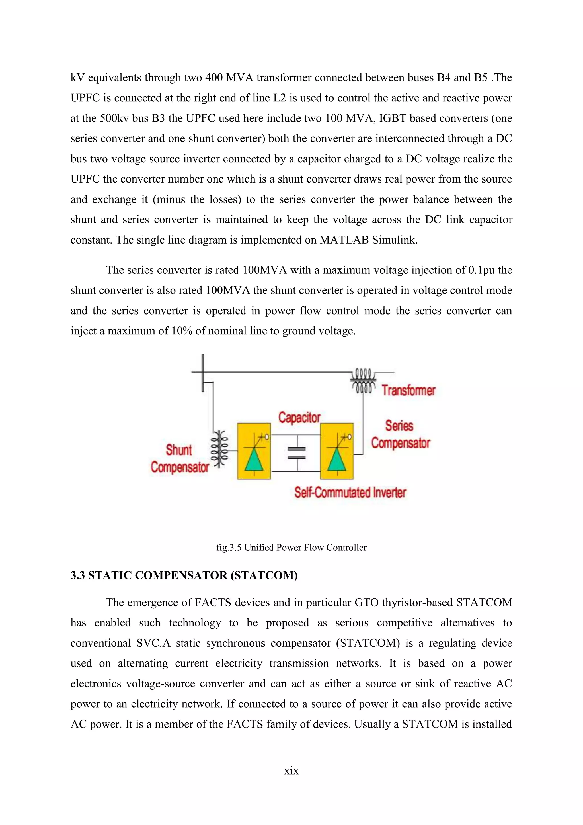
Description of UPFC as a versatile FACTS device controlling active/reactive power flow in transmission.
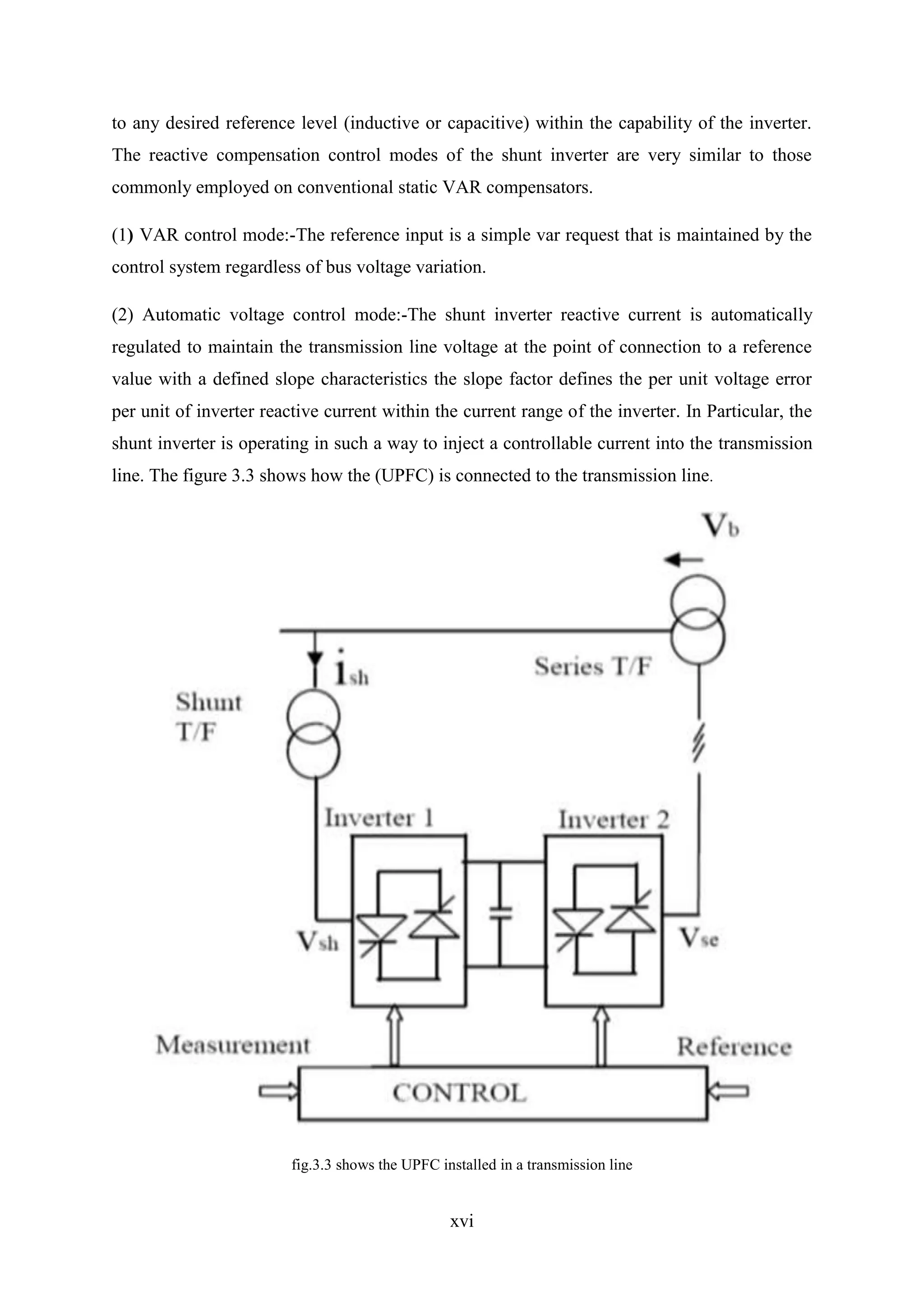
Details on the functioning of shunt and series inverters within UPFC for power control.
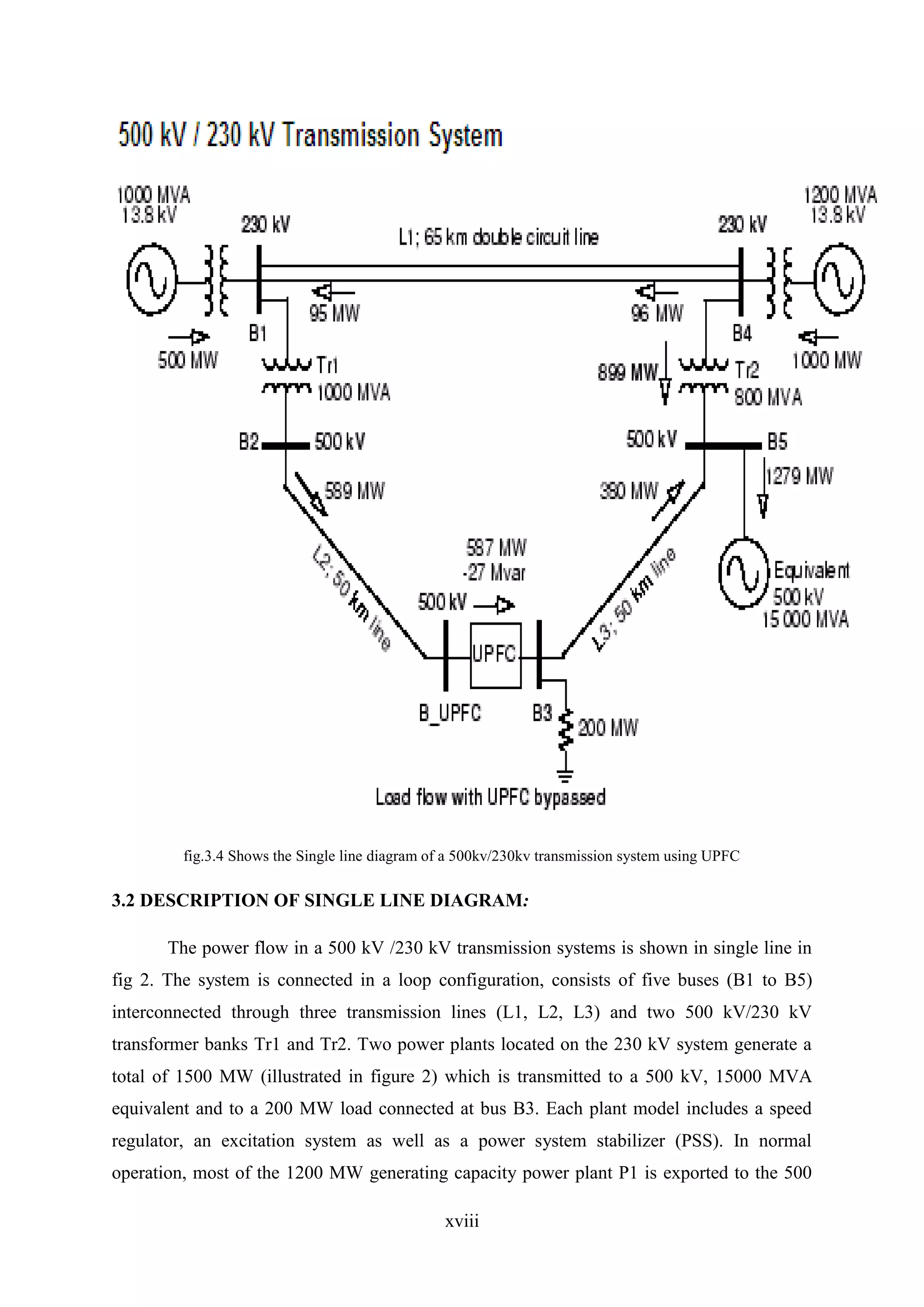
Illustration of UPFC's application in a 500 kV/230 kV system, with specific power and converter details.
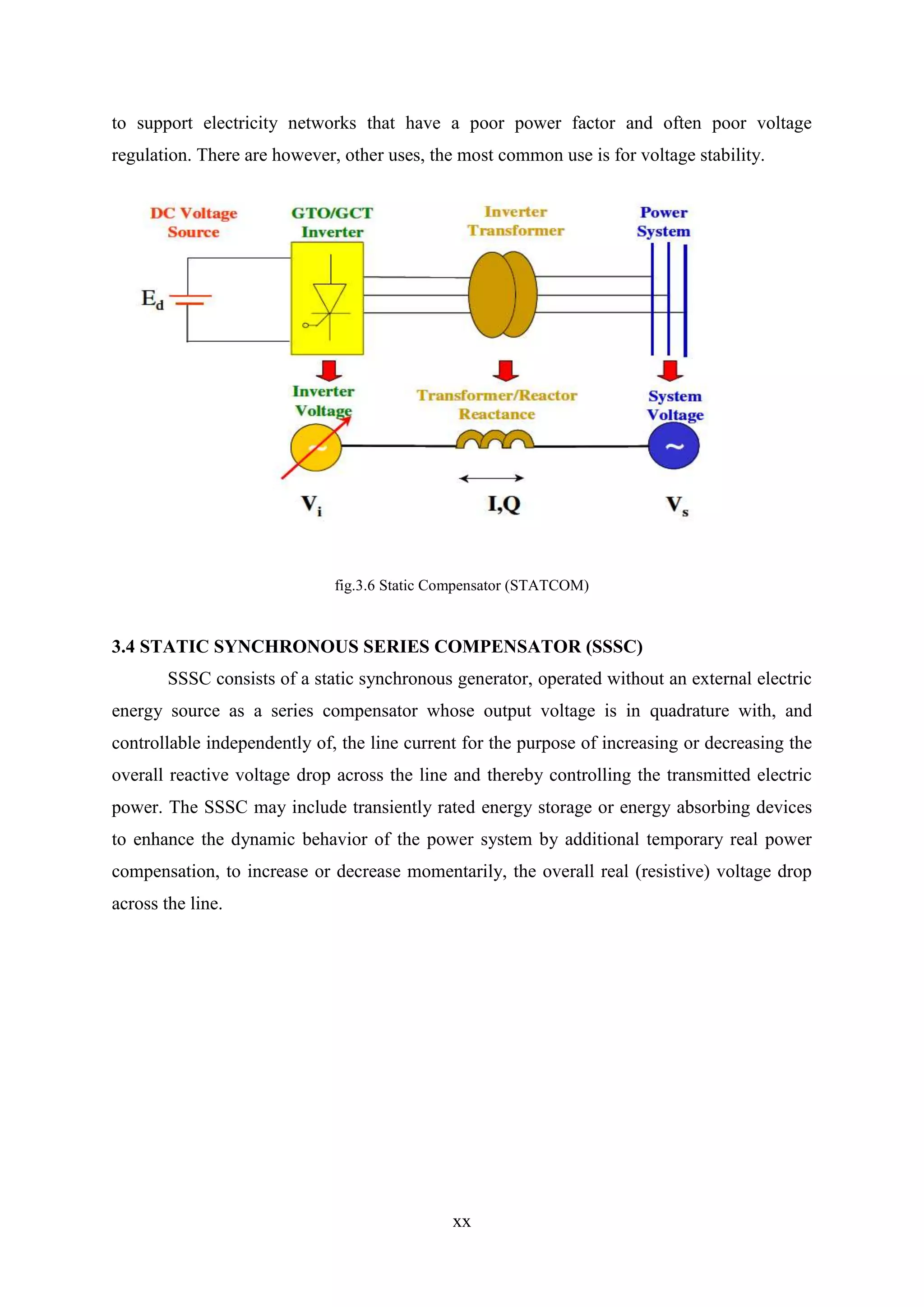
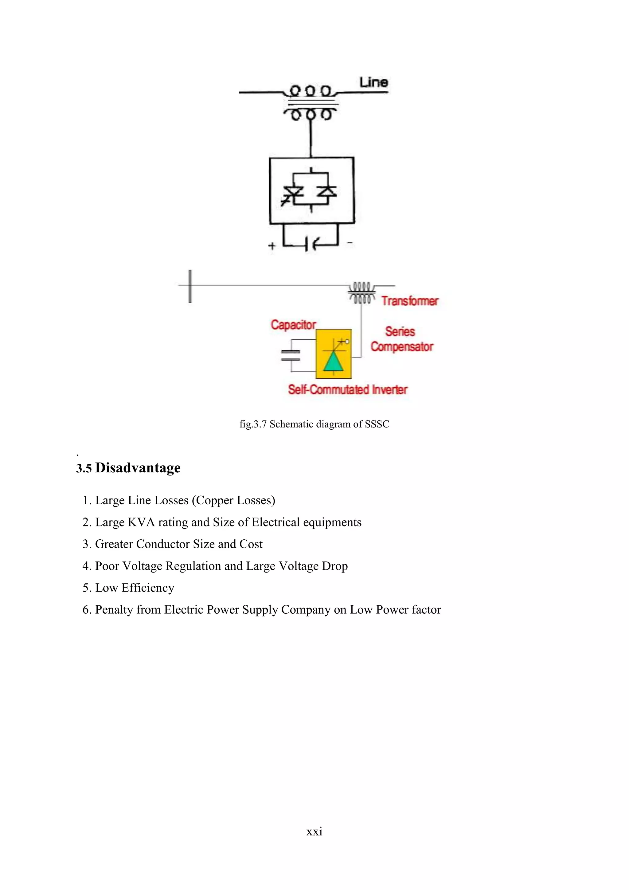
Describes STATCOM and SSSC's roles in voltage regulation and power stability.
Various applications including power flow control, stability improvement, and voltage enhancement.
Final thoughts on UPFC's contributions to enhancing power factor and stability in power systems.
Listing of references supporting the content on FACTS and UPFC technology.