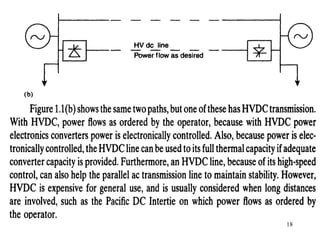
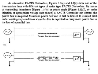
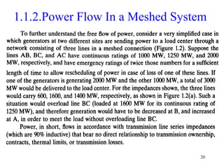
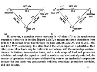
This document provides an overview of Flexible AC Transmission Systems (FACTS) technology. It outlines 6 units that will be covered: introduction to FACTS, voltage and current source converters, shunt compensators, series compensators, and combined controllers. The introduction discusses power flow limitations in AC systems and how FACTS devices can control parameters like voltage and impedance to improve power transfer capacity and stability. Key FACTS benefits are listed as well as the characteristics and tradeoffs of high power semiconductor devices used. The document aims to explain how FACTS controllers work and their applications in improving power system performance.

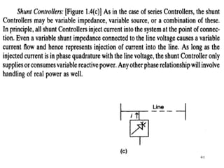
![17
1.1.1.Power Flow In Parallel Paths
Consider a very simple case of power flow [Figure 1.1(a)], through two
parallel paths (possibly corridors of several lines) from a surplus generation
area, shown as an equivalent generator on the left, to a deficit generation
area on the right. Without any control, power flow is based on the inverse of
the various transmission line impedances.
The lower impedance line may become overloaded and thereby limit the
loading on both paths even though the higher impedance path is not fully
loaded. There would not be an incentive to upgrade. current capacity of the
overloaded path, because this would further decrease the impedance and the
investment would be self-defeating particularly if the higher impedance path
already has enough capacity.](https://image.slidesharecdn.com/factsunit-1-220217005602/85/Facts-unit-1-17-320.jpg)