Unit 4 ultrasonic testing method
•Download as PPT, PDF•
0 likes•203 views

Ultrasonic testing methods: Introduction, Principle of operation, Piezoelectricity. Ultrasonic probes, CRO techniques,advantages, Limitation & typical applications. Applications in inspection of castings, forgings,Extruded steel parts, bars, pipes, rails and dimensions measurements. Case Study –Ultrasonography of human body.

More Related Content
What's hot
What's hot (20)
Similar to Unit 4 ultrasonic testing method
Similar to Unit 4 ultrasonic testing method (20)
More from Shivam Sharma
Recently uploaded
Recently uploaded (20)
Unit 4 ultrasonic testing method
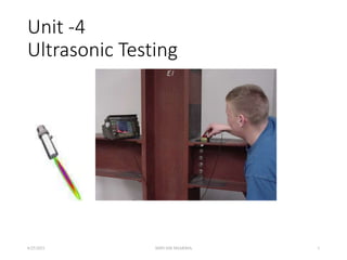
- 1. Unit -4 Ultrasonic Testing 6/25/2021 SHIVAM SHARMA 1
- 2. ULTRASONIC TESTING 6/25/2021 SHIVAM SHARMA 2
- 3. CONTENT • Introduction • Basic principles of sound generation • Principles of ultrasonic inspection • Test techniques • Equipment Transducers Instrumentation References of standards • Advantage of ultrasonic Testing • Limitation of ultrasonic Testing 6/25/2021 SHIVAM SHARMA 3
- 4. What are ultrasound? • Ultrasounds are acoustic waves with frequencies greater than 20 kHz, which are too high to be audible by humans. 6/25/2021 SHIVAM SHARMA 4
- 5. What are ultrasonic wave? •Ultrasonic waves are mechanic waves originated by the vibration/oscillation of the elementary particles (atoms or molecules) that constitutes the material (medium, more generally) • The propagation medium can be solid, liquid or gas • In liquid and gas only longitudinal waves are possible to propagate • The ultrasonic waves do not propagate in the vacuum 6/25/2021 SHIVAM SHARMA 5
- 6. Introduction •Ultrasonic testing (UT) is a family of non- destructive testing techniques based on propagation of ultrasonic waves in the object or the material tested. •For Ultrasonic testing application very short pulse of ultrasonic waves are transmitted into materials to detect internal flaws or to characterize the material. 6/25/2021 SHIVAM SHARMA 6
- 7. Introduction • This module presents an introduction to the NDT method of ultrasonic testing. • Ultrasonic testing uses high frequency sound energy to conduct examinations and make measurements. • Ultrasonic examinations can be conducted on a wide variety of material forms including castings, forgings, welds, and composites. • A considerable amount of information about the part being examined can be collected, such as the presence of discontinuities, part or coating thickness; and acoustical properties can often be correlated to certain properties of the material. 6/25/2021 SHIVAM SHARMA 7
- 8. Basic Principles of Sound • Sound is produced by a vibrating body and travels in the form of a wave. • Sound waves travel through materials by vibrating the particles that make up the material. • The pitch of the sound is determined by the frequency of the wave (vibrations or cycles completed in a certain period of time). • Ultrasound is sound with a pitch too high to be detected by the human ear. 6/25/2021 SHIVAM SHARMA 8
- 9. Basic Principles of Sound (cont.) • The measurement of sound waves from crest to crest determines its wavelength (λ). • The time is takes a sound wave to travel a distance of one complete wavelength is the same amount of time it takes the source to execute one complete vibration. • The sound wavelength is inversely proportional to its frequency. (λ = 1/f) • Several wave modes of vibration are used in ultrasonic inspection. The most common are longitudinal, shear, and Rayleigh (surface) waves. 6/25/2021 SHIVAM SHARMA 9
- 10. Basic Principles of Sound (cont.) • Ultrasonic waves are very similar to light waves in that they can be reflected, refracted, and focused. • Reflection and refraction occurs when sound waves interact with interfaces of differing acoustic properties. • In solid materials, the vibrational energy can be split into different wave modes when the wave encounters an interface at an angle other than 90 degrees. • Ultrasonic reflections from the presence of discontinuities or geometric features enables detection and location. • The velocity of sound in a given material is constant and can only be altered by a change in the mode of energy. 6/25/2021 SHIVAM SHARMA 10
- 11. Ultrasound Generation The transducer is capable of both transmitting and receiving sound energy. Ultrasound is generated with a transducer. A piezoelectric element in the transducer converts electrical energy into mechanical vibrations (sound), and vice versa. 6/25/2021 SHIVAM SHARMA 11
- 12. Principles of Ultrasonic Inspection • Ultrasonic waves are introduced into a material where they travel in a straight line and at a constant speed until they encounter a surface. • At surface interfaces some of the wave energy is reflected and some is transmitted. • The amount of reflected or transmitted energy can be detected and provides information about the size of the reflector. • The travel time of the sound can be measured and this provides information on the distance that the sound has traveled. 6/25/2021 SHIVAM SHARMA 12
- 13. Test Techniques • Ultrasonic testing is a very versatile inspection method, and inspections can be accomplished in a number of different ways. • Ultrasonic inspection techniques are commonly divided into three primary classifications. • Pulse-echo and Through Transmission (Relates to whether reflected or transmitted energy is used) • Normal Beam and Angle Beam (Relates to the angle that the sound energy enters the test article) • Contact and Immersion (Relates to the method of coupling the transducer to the test article) Each of these techniques will be discussed briefly in the following slides. 6/25/2021 SHIVAM SHARMA 13
- 14. • In pulse-echo testing, a transducer sends out a pulse of energy and the same or a second transducer listens for reflected energy (an echo). • Reflections occur due to the presence of discontinuities and the surfaces of the test article. • The amount of reflected sound energy is displayed versus time, which provides the inspector information about the size and the location of features that reflect the sound. f Test Techniques - Pulse-Echo plate crack 0 2 4 6 8 10 initial pulse crack echo back surface echo UT Instrument Screen 6/25/2021 SHIVAM SHARMA 14
- 15. Test Techniques – Pulse-Echo (cont.) Digital display showing signal generated from sound reflecting off back surface. Digital display showing the presence of a reflector midway through material, with lower amplitude back surface reflector. The pulse-echo technique allows testing when access to only one side of the material is possible, and it allows the location of reflectors to be precisely determined. 6/25/2021 SHIVAM SHARMA 15
- 16. Test Techniques – Through-Transmission 0 2 4 6 8 10 2 1 1 • Two transducers located on opposing sides of the test specimen are used. One transducer acts as a transmitter, the other as a receiver. • Discontinuities in the sound path will result in a partial or total loss of sound being transmitted and be indicated by a decrease in the received signal amplitude. • Through transmission is useful in detecting discontinuities that are not good reflectors, and when signal strength is weak. It does not provide depth information. T R T R 1 1 2 6/25/2021 SHIVAM SHARMA 16
- 17. Digital display showing received sound through material thickness. Digital display showing loss of received signal due to presence of a discontinuity in the sound field. Test Techniques – Through-Transmission 6/25/2021 SHIVAM SHARMA 17
- 18. Test Techniques – Normal and Angle Beam • In normal beam testing, the sound beam is introduced into the test article at 90 degree to the surface. • In angle beam testing, the sound beam is introduced into the test article at some angle other than 90. • The choice between normal and angle beam inspection usually depends on two considerations: - The orientation of the feature of interest – the sound should be directed to produce the largest reflection from the feature. - Obstructions on the surface of the part that must be worked around. 6/25/2021 SHIVAM SHARMA 18
- 19. 0 2 4 6 8 10 FWE BWE DE 2 IP IP = Initial Pulse FWE = Front Wall Echo DE = Defect Echo BWE = Back Wall Echo 0 2 4 6 8 10 FWE BWE 1 IP 1 2 Defect Test Techniques – Contact Vs Immersion • To get useful levels of sound energy into a material, the air between the transducer and the test article must be removed. This is referred to as coupling. • In contact testing (shown on the previous slides) a couplant such as water, oil or a gel is applied between the transducer and the part. • In immersion testing, the part and the transducer are place in a water bath. This arrangement allows better movement of the transducer while maintaining consistent coupling. • With immersion testing, an echo from the front surface of the part is seen in the signal but otherwise signal interpretation is the same for the two techniques. 6/25/2021 SHIVAM SHARMA 19
- 20. Piezoelectric Effect • The conversion of electrical pulses to mechanical vibrations and the conversion of returned mechanical vibrations back into electrical energy is the basis for ultrasonic testing. This conversion is done by the transducer using a piece of piezoelectric material (a polarized material having some parts of the molecule positively charged, while other parts of the molecule are negatively charged) with electrodes attached to two of its opposite faces. When an electric field is applied across the material, the polarized molecules will align themselves with the electric field causing the material to change dimensions. In addition, a permanently-polarized material such as quartz (SiO2) or barium titanate (BaTiO3) will produce an electric field when the material changes dimensions as a result of an imposed mechanical force. This phenomenon is known as the piezoelectric effect 6/25/2021 SHIVAM SHARMA 20
- 21. EQUIPMENT FOR ULTRASONIC APPLICATIONS • 1. Transducer • 2. Pulser (clock) • 3. Receiver/amplifier • 4. Display (screen) 1. The clock signals the pulser to provide a short, high-voltage pulse to the transducer while simultaneously supplying a voltage to the time-base trigger module. 2. The time-base trigger starts the “spot” in the CRT on its journey across the screen. 3. The voltage pulse reaches the transducer and is converted into mechanical vibrations (see “piezoelectricity”), which enter the test piece. These vibrations (energy) now travel along their “sound path” through the test piece. All this time, the spot is moving horizontally across the CRT. 6/25/2021 SHIVAM SHARMA 21
- 22. 4. The energy in the test piece now reflects off the interface (back wall) back toward the transducer, where it is reconverted into a voltage. (The reconverted voltage is a fraction of its original value.) 5. This voltage is now received and amplified by the receiver/amplifier. 6. The amplified voltage is sent to the “vertical (Y axis) plates” (top and bottom) in the CRT. At this time, the upper Y axis plate attracts the spot upward. This motion produces the “signal” on the screen that signifies the time that the energy has taken to make the round trip through the test piece, from the moment the energy leaves the transducer until it is received by the transducer. The spot is set to start its trip at the time the energy enters the test piece. This is manually adjusted by using the delay or zero control. This step is particularly necessary when using a Plexiglas delay line (see Glossary of Terms). 6/25/2021 SHIVAM SHARMA 22
- 23. Conti… 7. The same “packet” of returning energy has by this time reflected down off the test piece’s top interface and now makes a second trip down through the test piece. (The spot continues its horizontal journey across the screen.) The energy reflects once more off the back wall interface and returns again to be received and amplified. The 6/25/2021 SHIVAM SHARMA 23
- 24. CRO techniques • The cathode-ray oscilloscope (CRO) is a multipurpose display instrument used for the observation, measurement , and analysis of waveforms by plotting amplitude along y-axis and time along x-axis. • CRO is generally an x-y plotter; on a single screen it can display different signals applied to different channels. It can measure amplitude, frequencies and phase shift of various signals. Many physical quantities like temperature, pressure and strain can be converted into electrical signals by the use of transducers, and the signals can be displayed on the CRO. • A moving luminous spot over the screen displays the signal. CROs are used to study waveforms, and other time varying phenomena from very low to very high frequencies. 6/25/2021 SHIVAM SHARMA 24
- 25. The central unit of the oscilloscope is the cathoderay tube (CRT), and the remaining part of the CRO consists of the circuitry required to operate the cathode-ray tube. The CRO consists of the following: (i) CRT (ii) Vertical amplifier (iii) Delay line (iv) Horizontal amplifier (v) Time-base generator (vi) Triggering circuit (vii) Power supply 6/25/2021 SHIVAM SHARMA 25
- 26. 6/25/2021 SHIVAM SHARMA 26
- 27. 6/25/2021 SHIVAM SHARMA 27
- 28. Inspection Applications Some of the applications for which ultrasonic testing may be employed include: • Flaw detection (cracks, inclusions, porosity, etc.) • Erosion & corrosion thickness gauging • Assessment of bond integrity in adhesively joined and brazed components • Estimation of void content in composites and plastics • Measurement of case hardening depth in steels • Estimation of grain size in metals On the following slides are examples of some common applications of ultrasonic inspection. 6/25/2021 SHIVAM SHARMA 28
- 29. Thickness Gauging • Ultrasonic thickness gauging is routinely utilized in the petrochemical and utility industries to determine various degrees of corrosion/erosion. • Applications include piping systems, storage and containment facilities, and pressure vessels. 6/25/2021 SHIVAM SHARMA 29
- 30. Flaw Detection - Delaminations Signal showing multiple back surface echoes in an unflawed area. Additional echoes indicate delaminations in the member. Contact, pulse-echo inspection for delaminations on 36” rolled beam. 6/25/2021 SHIVAM SHARMA 30
- 31. Flaw Detection in Welds • One of the most widely used methods of inspecting weldments is ultrasonic inspection. • Full penetration groove welds lend themselves readily to angle beam shear wave examination. 6/25/2021 SHIVAM SHARMA 31
- 32. Equipment Equipment for ultrasonic testing is very diversified. Proper selection is important to insure accurate inspection data as desired for specific applications. In general, there are three basic components that comprise an ultrasonic test system: - Instrumentation - Transducers - Calibration Standards 6/25/2021 SHIVAM SHARMA 32
- 33. Transducers • Transducers are manufactured in a variety of forms, shapes and sizes for varying applications. • Transducers are categorized in a number of ways which include: - Contact or immersion - Single or dual element - Normal or angle beam • In selecting a transducer for a given application, it is important to choose the desired frequency, bandwidth, size, and in some cases focusing which optimizes the inspection capabilities. 6/25/2021 SHIVAM SHARMA 33
- 34. Contact Transducers Contact transducers are designed to withstand rigorous use, and usually have a wear plate on the bottom surface to protect the piezoelectric element from contact with the surface of the test article. Many incorporate ergonomic designs for ease of grip while scanning along the surface. 6/25/2021 SHIVAM SHARMA 34
- 35. Contact Transducers (cont.) • Contact transducers are available with two piezoelectric crystals in one housing. These transducers are called dual element transducers. • One crystal acts as a transmitter, the other as a receiver. • This arrangement improves near surface resolution because the second transducer does not need to complete a transmit function before listening for echoes. • Dual elements are commonly employed in thickness gauging of thin materials. 6/25/2021 SHIVAM SHARMA 35
- 36. Contact Transducers (cont.) • A way to improve near surface resolution with a single element transducer is through the use of a delay line. • Delay line transducers have a plastic piece that is a sound path that provides a time delay between the sound generation and reception of reflected energy. • Interchangeable pieces make it possible to configure the transducer with insulating wear caps or flexible membranes that conform to rough surfaces. • Common applications include thickness gauging and high temperature measurements. 6/25/2021 SHIVAM SHARMA 36
- 37. Transducers (cont.) • Angle beam transducers incorporate wedges to introduce a refracted shear wave into a material. • The incident wedge angle is used with the material velocity to determine the desired refracted shear wave according to Snell’s Law) • Transducers can use fixed or variable wedge angles. • Common application is in weld examination. 6/25/2021 SHIVAM SHARMA 37
- 38. Transducers (cont.) • Immersion transducers are designed to transmit sound whereby the transducer and test specimen are immersed in a liquid coupling medium (usually water). • Immersion transducers are manufactured with planar, cylindrical or spherical acoustic lenses (focusing lens). 6/25/2021 SHIVAM SHARMA 38
- 39. Instrumentation • Ultrasonic equipment is usually purchased to satisfy specific inspection needs, some users may purchase general purpose equipment to fulfill a number of inspection applications. • Test equipment can be classified in a number of different ways, this may include portable or stationary, contact or immersion, manual or automated. • Further classification of instruments commonly divides them into four general categories: D-meters, Flaw detectors, Industrial and special application. 6/25/2021 SHIVAM SHARMA 39
- 40. Instrumentation (cont.) • D-meters or digital thickness gauge instruments provide the user with a digital (numeric) readout. • They are designed primarily for corrosion/erosion inspection applications. • Some instruments provide the user with both a digital readout and a display of the signal. A distinct advantage of these units is that they allow the user to evaluate the signal to ensure that the digital measurements are of the desired features. 6/25/2021 SHIVAM SHARMA 40
- 41. Instrumentation (cont.) • Flaw detectors are instruments designed primarily for the inspection of components for defects. • However, the signal can be evaluated to obtain other information such as material thickness values. • Both analog and digital display. • Offer the user options of gating horizontal sweep and amplitude threshold. 6/25/2021 SHIVAM SHARMA 41
- 42. Instrumentation (cont.) • Industrial flaw detection instruments, provide users with more options than standard flaw detectors. • May be modulated units allowing users to tailor the instrument for their specific needs. • Generally not as portable as standard flaw detectors. 6/25/2021 SHIVAM SHARMA 42
- 43. Instrumentation (cont.) • Immersion ultrasonic scanning systems are used for automated data acquisition and imaging. • They integrate an immersion tank, ultrasonic instrumentation, a scanning bridge, and computer controls. • The signal strength and/or the time- of-flight of the signal is measured for every point in the scan plan. • The value of the data is plotted using colors or shades of gray to produce detailed images of the surface or internal features of a component. 6/25/2021 SHIVAM SHARMA 43
- 44. Images of a Quarter Produced With an Ultrasonic Immersion Scanning System Gray scale image produced using the sound reflected from the front surface of the coin Gray scale image produced using the sound reflected from the back surface of the coin (inspected from “heads” side) 6/25/2021 SHIVAM SHARMA 44
- 45. Calibration Standards Calibration is a operation of configuring the ultrasonic test equipment to known values. This provides the inspector with a means of comparing test signals to known measurements. Calibration standards come in a wide variety of material types, and configurations due to the diversity of inspection applications. Calibration standards are typically manufactured from materials of the same acoustic properties as those of the test articles. The following slides provide examples of specific types of standards. 6/25/2021 SHIVAM SHARMA 45
- 46. Calibration Standards (cont.) Thickness calibration standards may be flat or curved for pipe and tubing applications, consisting of simple variations in material thickness. Distance/Area Amplitude standards utilize flat bottom holes or side drilled holes to establish known reflector size with changes in sound path form the entry surface. ASTM Distance/Area Amplitude NAVSHIPS 6/25/2021 SHIVAM SHARMA 46
- 47. Calibration Standards (cont.) There are also calibration standards for use in angle beam inspections when flaws are not parallel to entry surface. These standards utilized side drilled holes, notches, and geometric configuration to establish time distance and amplitude relationships. IIW DSC DC Rhompas SC ASME Pipe Sec. XI 6/25/2021 SHIVAM SHARMA 47
- 48. Qualification Standards Qualification standards differ from calibration standards in that their use is for purposes of varying proper equipment operation and qualification of equipment use for specific codes and standards. AWS Resolution IOW Beam Profile DC-dB Accuracy 6/25/2021 SHIVAM SHARMA 48
- 49. Data Presentation • Information from ultrasonic testing can be presented in a number of differing formats. • Three of the more common formats include: • A-scan • B-scan • C-scan These three formats will be discussed in the next few slides. 6/25/2021 SHIVAM SHARMA 49
- 50. Data Presentation - A-scan • A-scan presentation displays the amount of received ultrasonic energy as a function of time. • Relative discontinuity size can be estimated by comparing the signal amplitude to that from a known reflector. • Reflector depth can be determined by the position of the signal on the horizontal sweep. Time Signal Amplitude Signal Amplitude Time 6/25/2021 SHIVAM SHARMA 50
- 51. Data Presentation - B-scan • B-scan presentations display a profile view (cross-sectional) of a test specimen. • Only the reflector depth in the cross- section and the linear dimensions can be determined. • A limitation to this display technique is that reflectors may be masked by larger reflectors near the surface. 6/25/2021 SHIVAM SHARMA 51
- 52. Data Presentation - C-scan • The C-scan presentation displays a plan type view of the test specimen and discontinuities. • C-scan presentations are produced with an automated data acquisition system, such as in immersion scanning. • Use of A-scan in conjunction with C-scan is necessary when depth determination is desired. Photo of a Composite Component C-Scan Image of Internal Features 6/25/2021 SHIVAM SHARMA 52
- 53. Advantage of Ultrasonic Testing • Sensitive to small discontinuities both surface and subsurface. • Depth of penetration for flaw detection or measurement is superior to other methods. • Only single-sided access is needed when pulse-echo technique is used. • High accuracy in determining reflector position and estimating size and shape. • Minimal part preparation required. • Electronic equipment provides instantaneous results. • Detailed images can be produced with automated systems. • Has other uses such as thickness measurements, in addition to flaw detection. 6/25/2021 SHIVAM SHARMA 53
- 54. Limitations of Ultrasonic Testing • Surface must be accessible to transmit ultrasound. • Skill and training is more extensive than with some other methods. • Normally requires a coupling medium to promote transfer of sound energy into test specimen. • Materials that are rough, irregular in shape, very small, exceptionally thin or not homogeneous are difficult to inspect. • Cast iron and other coarse grained materials are difficult to inspect due to low sound transmission and high signal noise. • Linear defects oriented parallel to the sound beam may go undetected. • Reference standards are required for both equipment calibration, and characterization of flaws. 6/25/2021 SHIVAM SHARMA 54
- 55. Glossary of Terms • Acoustical properties: ultrasonic material characteristics such as velocity, impedance, and attenuation. • ASTM: acronym for American Society for Testing and Materials. This society is extensively involved in establishing standards for materials and the testing of materials. • Back reflection: a display signal that corresponds to the far surface of a test specimen, side opposite to transducer when testing with longitudinal waves. • Band width: a range of frequencies either transmitted or received, may be narrow or broad range. • B-scan: presentation technique displaying data in a cross- sectional view. 6/25/2021 SHIVAM SHARMA 55
- 56. Glossary of Terms • Calibration: a sequence of instrument control adjustments/instrument responses using known values to verify instrument operating characteristics. Allows determination of unknown quantities from test materials. • CRT: acronym for Cathode Ray Tube. Vacuum tube that utilizes one or more electron guns for generating an image. • C-scan: presentation technique that displays specimen data in a plan type view. • DAC (Distance Amplitude Correction-curves): a graphical method of allowing for material attenuation. Percentage of DAC is often used as a means of acceptance criteria. • Discontinuity: an interruption in the physical structure of a material, examples include fissures, cracks, and porosity. 6/25/2021 SHIVAM SHARMA 56
- 57. Glossary of Terms • IIW: calibration standard meeting the specification of the International Institute of Welding. • Longitudinal (Compression) waves: ultrasonic mode of propagation in which the particle vibration is parallel to the direction of propagation. • Near Surface Resolution: the ability of an ultrasonic system to display reflectors located close to the entry surface. • Pulse-echo: ultrasonic test method that utilizes reflected sound as a means of collecting test data. • Rayleigh (Surface) waves: ultrasonic mode of propagation where the sound travels along the surface, particle vibration is elliptical. 6/25/2021 SHIVAM SHARMA 57
- 58. Glossary of Terms • Reflection: the changing in direction of sound waves as they strike a surface. • Snell’s Law: an equation of ratios used to determine incident or refracted angle of sound, denotes angle/velocity relationship. • Sweep display: horizontal line on the lower portion of the display, often called the time base line. • Through transmission: test technique in which ultrasound is transmitted from one transducer and received by a separate transducer on the opposite side of the test specimen. • Wavelength: the distance that a sound wave travels as it completes one cycle, normally measured in inches or millimeters. 6/25/2021 SHIVAM SHARMA 58
- 59. Case Study – Ultrasonography of human body. 6/25/2021 SHIVAM SHARMA 59
- 60. For More Information The Collaboration for NDT Education www.ndt-ed.org The American Society for Nondestructive Testing www.asnt.org 6/25/2021 SHIVAM SHARMA 60