Downloaded 181 times

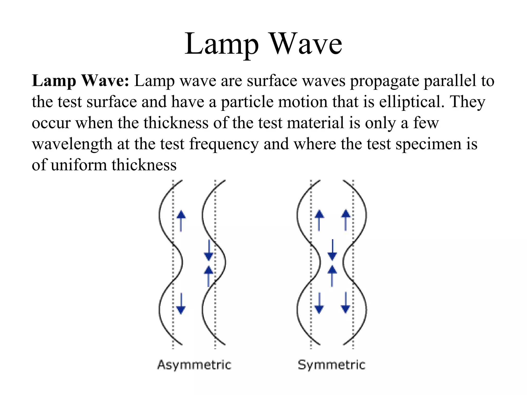
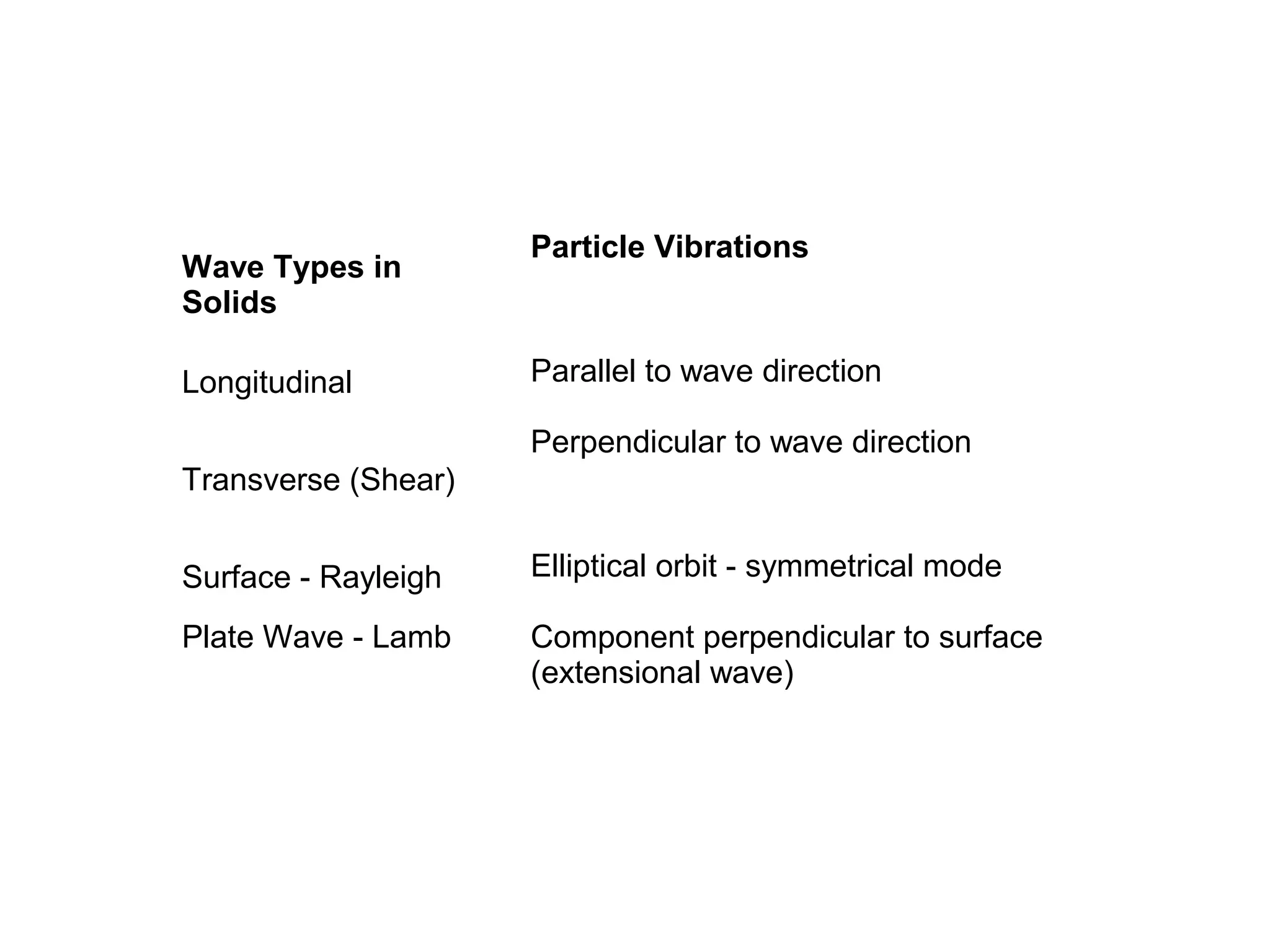
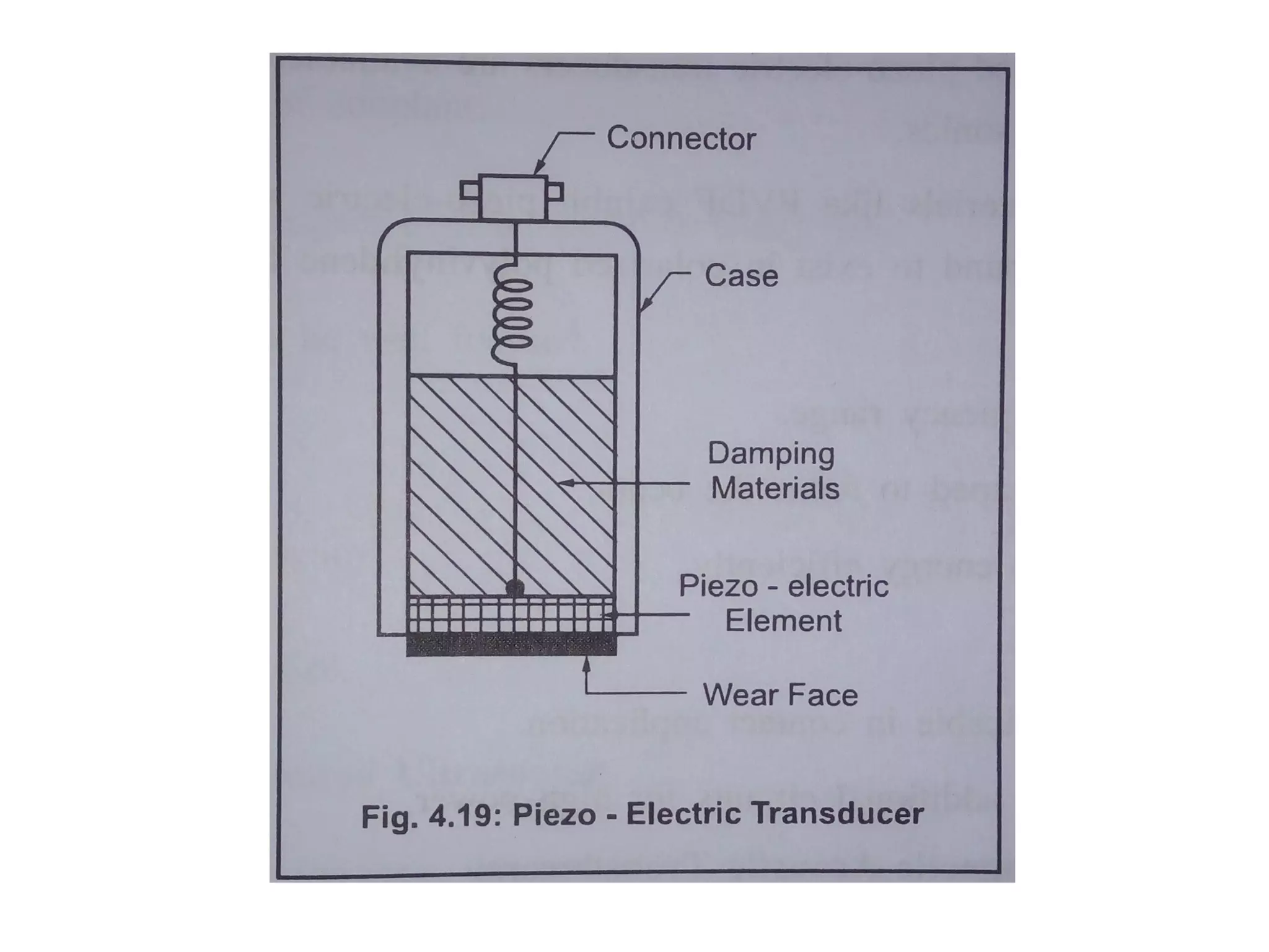
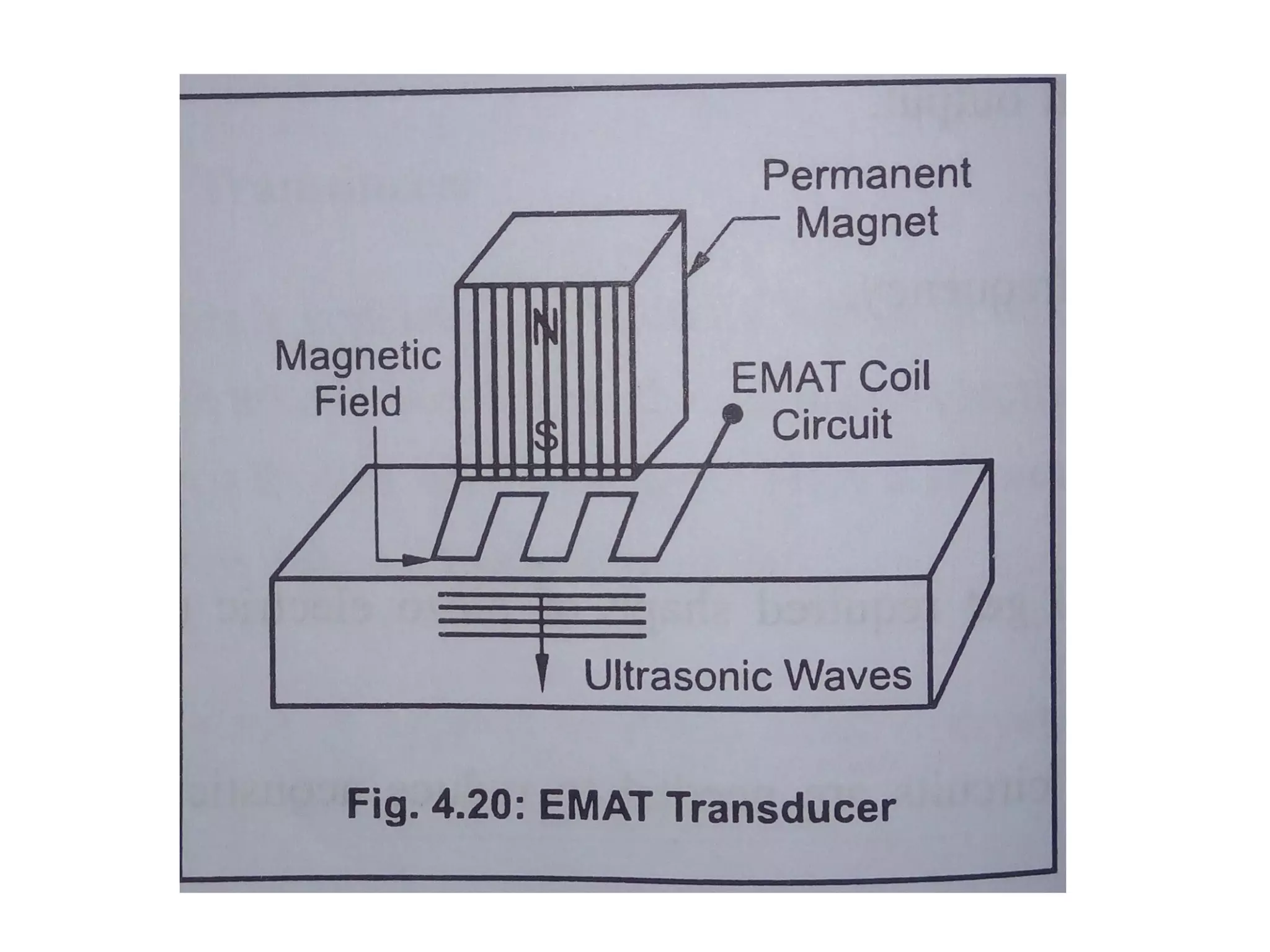
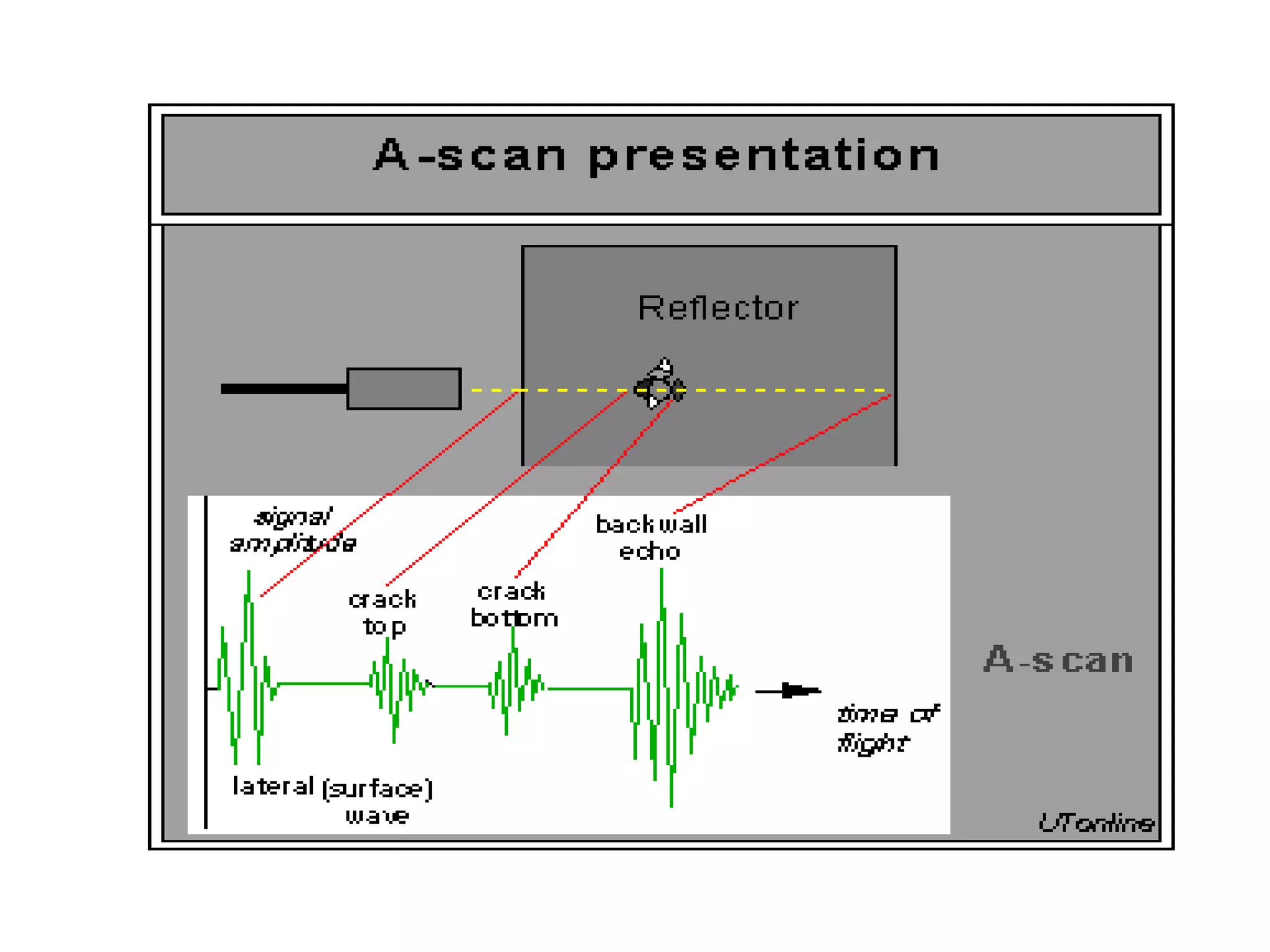
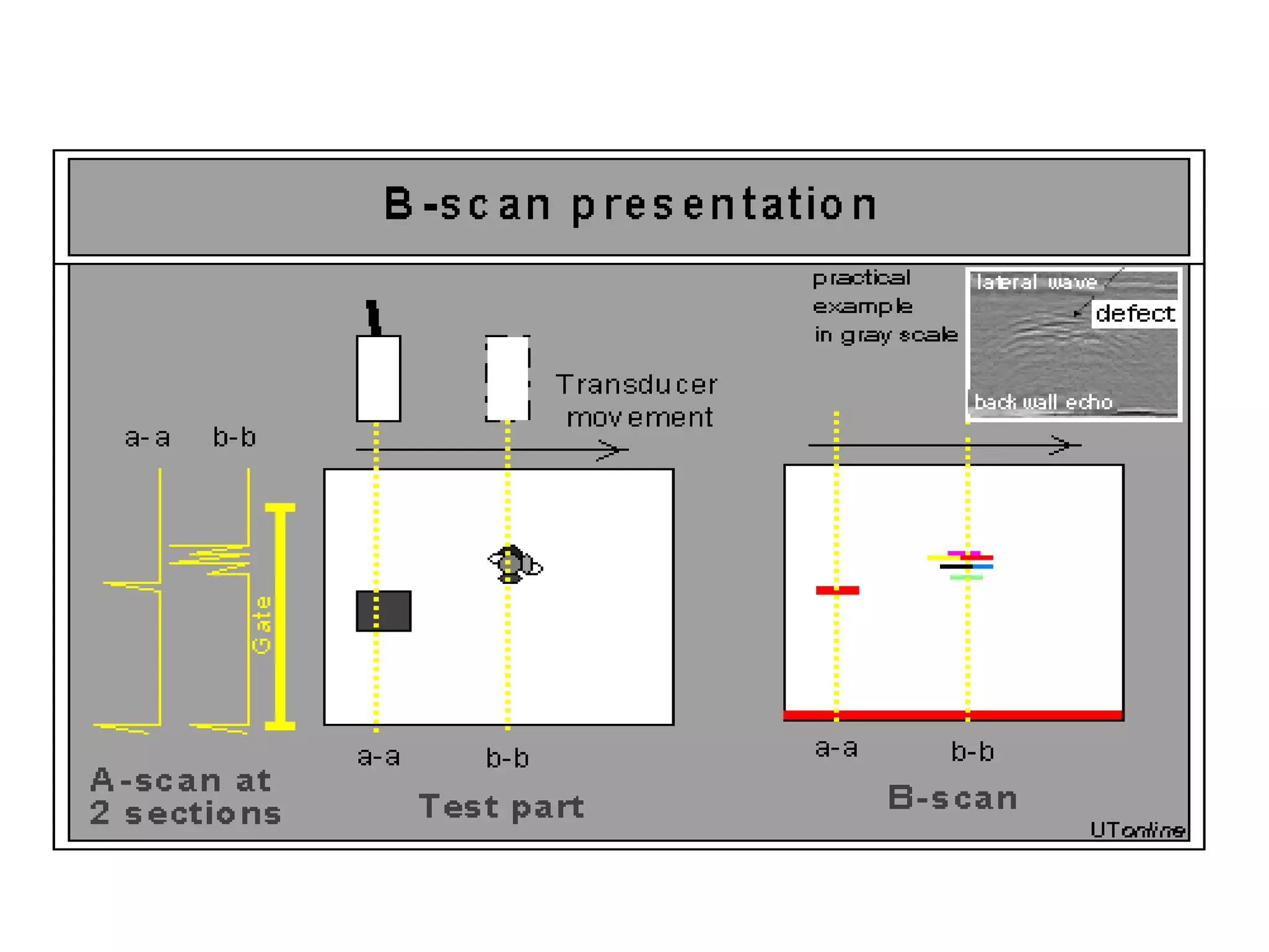
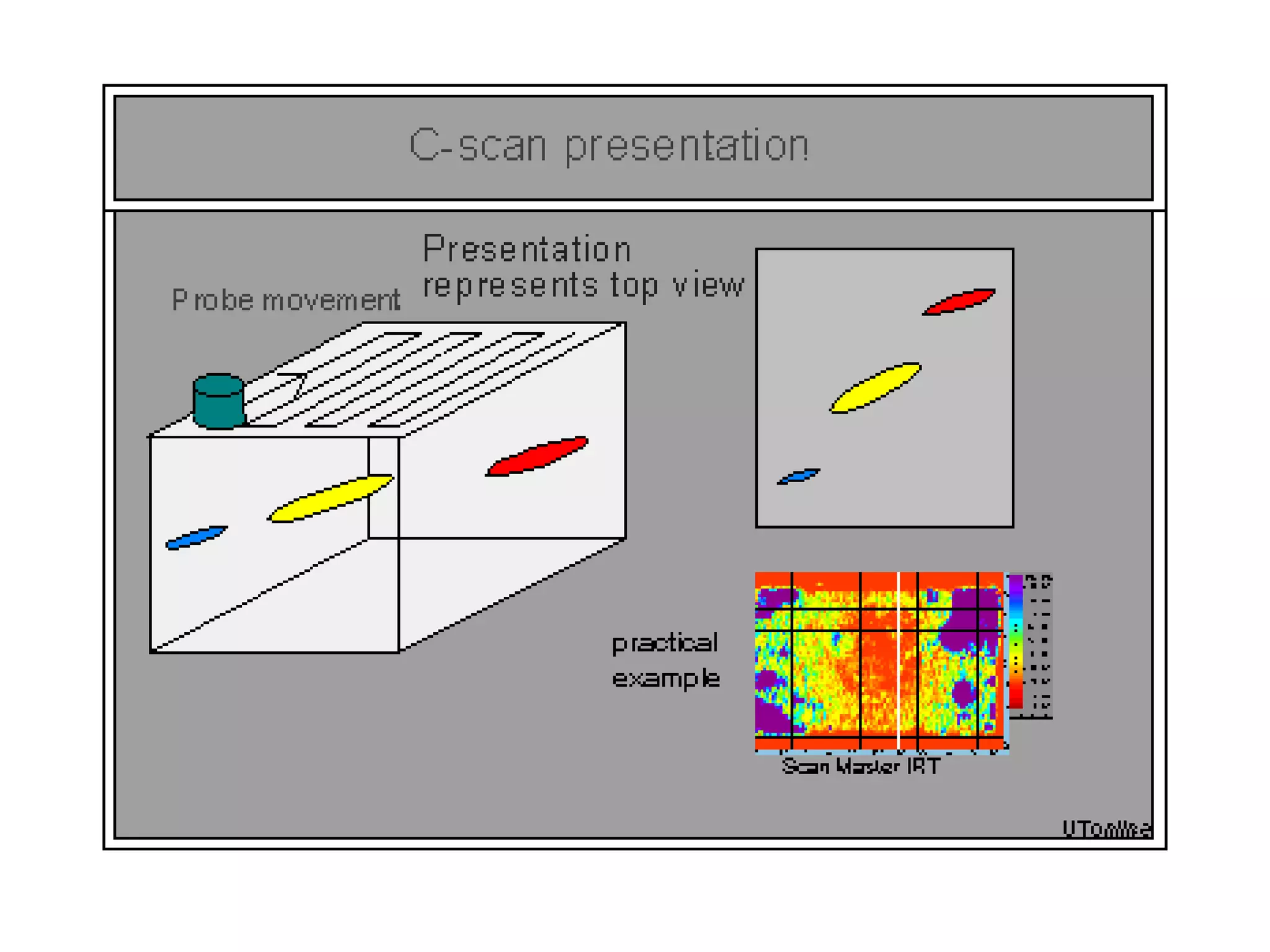


Ultrasonic testing (UT) is a non-destructive method used to evaluate the thickness and internal structure of materials using high frequency sound waves. The document covers the principles, types of ultrasonic waves, testing methods (pulse-echo, through transmission, contact, immersion), and various ultrasonic transducers, detailing their construction, working principles, advantages, and limitations. It also explains data presentation formats (A-scan, B-scan, C-scan) and the applications of UT in detecting flaws and determining material properties.


